
You also want an ePaper? Increase the reach of your titles
YUMPU automatically turns print PDFs into web optimized ePapers that Google loves.
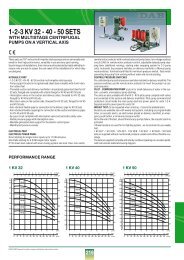
OUT-LINE ON THE STANDARDS<br />
UNI 9490 - UNI 10779<br />
The principles for the creation of fire-fighting systems is established by the National Unification body UNI;<br />
- the UNI 9490 standard concerns equipment for automatic fire-fighting sprinkler systems<br />
- the UNI 10779 standard concerns the design and installation of fire-fighting systems with hydrant networks<br />
Other references for building fire-fighting pressure sets are contained in UNI 9489 standard<br />
“Sprinkler fire extinguishing systems”.<br />
The customers, designers, producers, installers, testers and public control and security bodies are bound to comply<br />
with the UNI standards.<br />
The UNI 9490 and UNI 10779 standards describe the standards of the fire-fighting systems, regarding installation<br />
features of both automatic pumps and systems.<br />
A pump group station must be foreseen and used exclusively for fire-fighting purposes, having at least one bordering<br />
wall with uncovered space.<br />
The temperature within the pumping station must not be below:<br />
+ 4°C if only electric pumps are installed<br />
+ 10°C if Diesel motor-pumps are installed<br />
When Diesel motor-pumps are installed, the room must have a ventilation system that prevents the temperature rising<br />
above 40°C.<br />
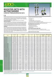
COMPOSITION OF UNI 9490-10779 <strong>SETS</strong><br />
The units comprise:<br />
a) one or two main pumps operated by motors or Diesel engines (UNI 9490 4.9.2.2).<br />
The motor-pump connection must (P1) (P2) allow the hydraulic assembly (the real and proper pump) to be<br />
dismounted from the motor.<br />
b) compensating pump, if present (P3).<br />
The compensating pump, also known as the pilot pump, compensates the small pressure drops in the fire fighting<br />
system caused by dripping, leaks, etc.<br />
c) a control panel for each pump (1) (2).<br />
Each electric pump has its own electrical panel (UNI 9490 4.9.4.7.) powered by separate lines<br />
(UNI 9490 4.11.3.3.d). The diesel pump is independently fuelled (diesel tank for 60 hours autonomy) and started with<br />
two batteries, constantly charged thanks to a double battery charger.<br />
d) Starting device for each pump (5).<br />
The starting device, comprising a pressure switch for each pump, must start the pump at a pressure ranging from<br />
between 75% and 85% of the pump pressure with the delivery closed (UNI 9490 4.9.3.4.).<br />
e) various hydraulic accessories (valves, stub pipes, manifolds, etc.)<br />
- The shut-off valves must show whether they are open or closed (UNI 10779 6.3) and must also be lockable<br />
(UNI 9490 5.1.4.).<br />
- The check valves on the pump delivery side are inspectable (UNI 9489 8.4.).<br />
- The full scale of the pressure gauges must reach 150% of maximum operating pressure.<br />
- Flow meters must comply with UNI ISO 2548 - 3555 with a tolerance of 5%.<br />
- The rated pressure of the system components must be at least PN 12 (UNI 10779 6.1)<br />
Each pump has its own suction line (UNI 4.9.3) while the same delivery manifold is used for all the pumps.<br />
All the above is mounted on the galvanised steel base. This must:<br />
- support and align the various components in the set<br />
108<br />
®