As and Epitaxial-Growth MnSi Thin Films - OPUS Würzburg
As and Epitaxial-Growth MnSi Thin Films - OPUS Würzburg
As and Epitaxial-Growth MnSi Thin Films - OPUS Würzburg

You also want an ePaper? Increase the reach of your titles
YUMPU automatically turns print PDFs into web optimized ePapers that Google loves.
120 A. Fabrication of Four-Terminal Corbino Gated Structure<br />
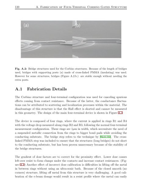
Fig. A.2: Bridge structures used for the Corbino sturctures. Because of the length of bridges<br />
used, bridges with supporting posts (a) made of cross-linked PMMA (insulating) was used.<br />
However for some structures, bridges (Figure A.2.b.) are stable enough without needing the<br />
extra posts.<br />
A.1 Fabrication Details<br />
The Corbino structure <strong>and</strong> four-terminal configuration was used for canceling spurious<br />
effects coming from contact resistance. Because of the latter, the conductance fluctuations<br />
can be attributed to scattering <strong>and</strong> localization processes within the material. The<br />
disadvantage of this structure is that the Hall effect is shorted <strong>and</strong> cannot be measured<br />
in this geometry. The design of the main four-terminal device is shown in Figure A.1<br />
The device is composed of four rings, where the current is applied in rings R1 <strong>and</strong> R4<br />
withthevoltagedropmeasured alongringsR2<strong>and</strong>R3, followingthenormal four-terminal<br />
measurement configuration. These rings are 1µm in width, which necessitate the need of<br />
a suspended metallic connection from the rings to bigger bond pads while avoiding the<br />
conducting substrate. The bridge step refers to the technique by [Borz 05]. The crosslinked<br />
PMMA step was included to ensure that the structures (long bridges) do not short<br />
to the conducting substrate, but has been proven unnecessary because of the stability of<br />
the bridge structures.<br />
The gradient of dose factors are to correct for the proximity effect. Lower dose causes<br />
left-over resist to form clumps under the contacts <strong>and</strong> increase contact resistances. (Figure<br />
A.1) Another effect of incorrect dose calibration is difficulties in lifting off the metal<br />
in between rings without using an ultra-sonic bath. Because of the closed smooth (no<br />
corners) structure, lifting off metal from this structure is very challenging. A good calibration<br />
of the e-beam dosage would result in a resist profile where the metal can easily