As and Epitaxial-Growth MnSi Thin Films - OPUS Würzburg
As and Epitaxial-Growth MnSi Thin Films - OPUS Würzburg
As and Epitaxial-Growth MnSi Thin Films - OPUS Würzburg

Create successful ePaper yourself
Turn your PDF publications into a flip-book with our unique Google optimized e-Paper software.
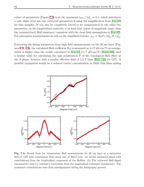
84 7. Magnetotransport with H ‖ [111]<br />
values of parameters (Figure 7.3) is at the maximum αρ xx /βρ 2 xx ≈ 0.1, which introduces<br />
a only slight error into the extracted parameters if using the simplification from [Lee 07]<br />
for thin samples. It can also be completely forced to be compensated by the other two<br />
parameters, as the longitudinal resistivity is at least four orders of magnitude larger than<br />
the (symmetrized) Hall resistance, consistent with the clean limit assumptions in [Lee 07].<br />
Forsubsequent measurements werelyonthesimplifiedformula: ρ xy ≈ R 0 B+βρ 2 xx M+ρT xy .<br />
Extracting the fitting parameters from high field measurements on the 20 nm layer (Figures7.4-7.6),<br />
thecalculatedHallcoefficient R H ismeasured as≈17nΩ-cm/Tonaverage,<br />
which is higher than the results calculated in [Lee 07].(≈ 7 nΩ-cm/T) [Neub 09b] used<br />
a similar value for calculating the spin polarization P of the topological Hall effect at<br />
the A-phase, however with a smaller effective field of 2.5 T than [Ritz 13a] (≈ 13T). A<br />
possible expanation would be a reduced carrier concentration in <strong>MnSi</strong> thin films arising<br />
0.37<br />
0.36<br />
0.35<br />
R xy<br />
(ohm)<br />
0.34<br />
0.33<br />
0.32<br />
-3000 -2000 -1000 0 1000 2000 3000<br />
Magnetic Field (mT)<br />
0.352<br />
0.02<br />
R EVEN xy (Ω)<br />
0.348<br />
R ODD xy (Ω)<br />
0.00<br />
0.344<br />
-0.02<br />
-3000 -2000 -1000 0 1000 2000 3000<br />
Magnetic Field (mT)<br />
-3000 -2000 -1000 0 1000 2000 3000<br />
Magnetic Field (mT)<br />
Fig. 7.4: Result from low temperature Hall measurements for 20 nm layer at a saturation<br />
field of ±3T with countinuous field sweep rate of 30mT/min: (a) Actual measured signal with<br />
contributions from the longitudinal component of the Hallbar, (b) The extracted Hall signal<br />
(asymmetric) <strong>and</strong> (c) resistance corrections from the longitudinal resistance (symmetric). The<br />
symmetric contributions arise from misalignments during the lithography process.