Ways to Conserve Energy on Board - DNV
Ways to Conserve Energy on Board - DNV
Ways to Conserve Energy on Board - DNV

You also want an ePaper? Increase the reach of your titles
YUMPU automatically turns print PDFs into web optimized ePapers that Google loves.
HT circuit<br />
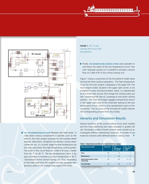
Figure 1. HT, LT and<br />
cooling SW circuit with<br />
Simulati<strong>on</strong>X.<br />
Finally, the seawater (SW) cooling system uses seawater <str<strong>on</strong>g>to</str<strong>on</strong>g><br />
cool down the water of the low-temperature circuit. Two<br />
main seawater pumps run in parallel <str<strong>on</strong>g>to</str<strong>on</strong>g> provide a volume<br />
flow of 2,300 m 3 /h <str<strong>on</strong>g>to</str<strong>on</strong>g> the central cooling unit.<br />
LT circuit<br />
Figure 1 shows a screenshot of the Simulati<strong>on</strong>X model representing<br />
the three cooling subsystems. The high-temperature<br />
circuit for the main engine is displayed in the upper left. The<br />
main engine model, located in the upper right corner, is not<br />
modelled in every mechanical detail; rather, it is represented<br />
by the three heat sources that charge the cooling water system,<br />
comprising the lube oil, scavenge air and jacket cooling<br />
systems. The heat exchangers (jagged comp<strong>on</strong>ents) shown<br />
in the upper right area of the schematic bel<strong>on</strong>g <str<strong>on</strong>g>to</str<strong>on</strong>g> the lowtemperature<br />
circuit, which is <strong>on</strong>ly represented in part <strong>on</strong> this<br />
screenshot. The structure of the Simulati<strong>on</strong>X model matches<br />
the corresp<strong>on</strong>ding process flow very closely.<br />
SW circuit<br />
The low-temperature (LT) system likewise uses fresh water. It<br />
cools down various comp<strong>on</strong>ents in parallel, such as the<br />
lube oil, the main engine scavenge air, the auxiliary diesel<br />
engines, alterna<str<strong>on</strong>g>to</str<strong>on</strong>g>rs, refrigerant c<strong>on</strong>densers, excess steam<br />
c<strong>on</strong>denser, etc. In a further stage the low-temperature system<br />
also cools down the high-temperature cooling system.<br />
The water in this circuit flows at 1,840 m 3 /h and is cooled<br />
from 50 °C <str<strong>on</strong>g>to</str<strong>on</strong>g> 36 °C. The low-temperature circuit is bypass-c<strong>on</strong>trolled<br />
<str<strong>on</strong>g>to</str<strong>on</strong>g> maintain a c<strong>on</strong>stant temperature of 36 °C<br />
downstream of the central cooling unit. Thus, depending<br />
<strong>on</strong> the heat load from the engines and the seawater temperature,<br />
parts of the cooling water bypass the cooler.<br />
Variants and Simulati<strong>on</strong> Results<br />
Several variati<strong>on</strong>s of the actual cooling circuit were studied,<br />
and the most promising two were analysed in greater detail.<br />
Simulati<strong>on</strong> studies of both variants were carried out <str<strong>on</strong>g>to</str<strong>on</strong>g><br />
investigate different operati<strong>on</strong>al scenarios. A number of operati<strong>on</strong>al<br />
scenarios were defined based <strong>on</strong> various main<br />
Table 1: Operati<strong>on</strong>al profile of a representative voyage<br />
Operati<strong>on</strong>al mode Time (%) ME<br />
workload<br />
(% MCR)<br />
No. of aux.<br />
engines<br />
used<br />
Port 30 0 1<br />
Manoeuvre 5 20 3<br />
Restricted water /slow<br />
steaming<br />
35 45 2 – 3*<br />
Sea passage 30 65 1 – 3*<br />
* Varying number of auxiliary engines<br />
01/2013<br />
35