Requirements for Unity of Application - Japan Patent Office
Requirements for Unity of Application - Japan Patent Office
Requirements for Unity of Application - Japan Patent Office

Create successful ePaper yourself
Turn your PDF publications into a flip-book with our unique Google optimized e-Paper software.
[Example 45]<br />
[Title <strong>of</strong> the Invention]<br />
Structure <strong>of</strong> anti-slipping device <strong>of</strong> blind nut<br />
[Claims]<br />
1. Anti-slipping device <strong>of</strong> blind consisting <strong>of</strong> a hollow cylinder (36) fabricated <strong>of</strong> a material<br />
capable <strong>of</strong> plastic de<strong>for</strong>mation, having the female thread (12) on its inside front end and a<br />
flange (14) on its back end;<br />
Wherein a groove (24) cut in the direction <strong>of</strong> the outside <strong>of</strong> the radius in the surface <strong>of</strong> the<br />
mounting hole (22) <strong>of</strong> the part to be fastened (16); and the mid-section <strong>of</strong> the blind nut (34)<br />
expanding in the outside direction <strong>of</strong> the radius including the said groove (22), thus<br />
preventing the slippage <strong>of</strong> the blind nut. (See Figures 1 and 2)<br />
2. The tool <strong>for</strong> <strong>for</strong>ming the anti-slippage groove (22) comprising a guide portion (26) <strong>of</strong> the<br />
blind nut, which is inserted into the pre-drilled mounting hole <strong>of</strong> the piece to be fastened, a<br />
flange (30) able to be inserted in said mounting hole (22) provided at the rear side <strong>of</strong> said<br />
guide, and an edge (32) affixed at an angle <strong>of</strong> 15-40 o and protruding in the outside<br />
direction <strong>of</strong> the radius <strong>of</strong> the edge <strong>of</strong> the flange. (See Figures 3 and 4)<br />
[Excerpt from Detail Description <strong>of</strong> the Invention and Drawings]<br />
This invention concerns the structure <strong>of</strong> anti-slippage device <strong>of</strong> blind nuts when a large<br />
torque is applied to the piece being held by the blind nut.<br />
The conventional blind nut was tightened by means <strong>of</strong> an impact wrench and a like so that<br />
a large torque is applied to the blind nut and crimping becomes loose, the blind nut turned.<br />
This invention combines the grooves in the mounting hole and the anti-slippage structure<br />
<strong>of</strong> the blind nut in order to prevent slippage, and the tool in Figures 3 and 4 is appropriate <strong>for</strong><br />
<strong>for</strong>ming the grooves in the mounting hole (22).<br />
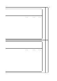
(After crimping)<br />
Grooving tool<br />
Figure 2<br />
Figure 3<br />
Figure 1<br />
Figure 4<br />
[Explanation]<br />
The related invention (Claim 2), the tool does not manufacture the specified invention<br />
(Claim 1), the anti-slippage structure <strong>of</strong> the blind nut, but it is appropriate <strong>for</strong> cutting the<br />
grooves in the mounting hole to accept the structure <strong>of</strong> the specified invention blind nut. Both<br />
inventions have the relationship between the product and machines, instruments, equipment or<br />
other things <strong>for</strong> manufacturing the product.<br />
[Concerned Section]<br />
<strong>Patent</strong> Law Section 37(iii)<br />
84