Innovation in Global Power - Parsons Brinckerhoff
Innovation in Global Power - Parsons Brinckerhoff
Innovation in Global Power - Parsons Brinckerhoff

Create successful ePaper yourself
Turn your PDF publications into a flip-book with our unique Google optimized e-Paper software.
A technical<br />
journal by<br />
<strong>Parsons</strong><br />
Br<strong>in</strong>ckerhoff<br />
employees<br />
and colleagues<br />
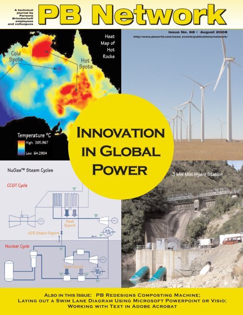
Heat<br />
Map of<br />
Hot<br />
Rocks<br />
Issue No. 68 • August 2008<br />
http://www.pbworld.com/news_events/publications/network/<br />
NuGas Steam Cycles<br />
<strong>Innovation</strong><br />
<strong>in</strong> <strong>Global</strong><br />
<strong>Power</strong><br />
3 MW M<strong>in</strong>i Hydro Station<br />
Also <strong>in</strong> this Issue: PB Redesigns Compost<strong>in</strong>g Mach<strong>in</strong>e;<br />
Lay<strong>in</strong>g out a Swim Lane Diagram Us<strong>in</strong>g Microsoft <strong>Power</strong>po<strong>in</strong>t or Visio;<br />
Work<strong>in</strong>g with Text <strong>in</strong> Adobe Acrobat
<strong>Innovation</strong> <strong>in</strong> <strong>Global</strong> <strong>Power</strong><br />
TABLE OF<br />
CONTENTS<br />
Guest Editors for this<br />
issue: Kather<strong>in</strong>e Jackson<br />
and Arthur Ekwue.<br />
Guest Technical Reviewers:<br />
John Douglas, Ferrel Ensign,<br />
Steve Loyd, Chris Meadows,<br />
Brian Van Weele, and<br />
John Wichall.<br />
Special thanks to Paul Kenyon<br />
and Matthew Chan for their<br />
assistance.<br />
Cover photo (lower right):<br />
©Tony Mulholland<br />
Note: Soon after distribution,<br />
this issue will be available<br />
on the Web at http://www.<br />
pbworld.com/news_events/<br />
publications/network/<br />
Issue_68/68_<strong>in</strong>dex.asp<br />
Introduction (Burton) ...........................................................3<br />
GENERATION<br />
THERMAL – ACHIEVING NEW EFFICIENCIES,<br />
REDUCING CARBON EMISSIONS<br />
Best Practices Across a Range of Technologies (Kenyon)..4<br />
The Effect of Carbon Capture and Storage and<br />
Carbon Pric<strong>in</strong>g on the Competitiveness of Gas<br />
Turb<strong>in</strong>e <strong>Power</strong> Plants (Cook)..................................................5<br />
The NuGas TM Concept: Comb<strong>in</strong><strong>in</strong>g a Nuclear <strong>Power</strong><br />
Plant with a Gas-fired Plant (Willson, Smith).................8<br />
PB Inspections Help To Ensure <strong>Power</strong> Plant Safety<br />
(Gray) .................................................................................................11<br />
Project Brief: Us<strong>in</strong>g Monte Carlo Techniques to<br />
Size a <strong>Power</strong> Station (Emmerton).....................................13<br />
Project Brief: Energiz<strong>in</strong>g S<strong>in</strong>gapore’s Economy (Gill)........13<br />
Comb<strong>in</strong>ed Heat and <strong>Power</strong> for USA’s Largest<br />
Residential Development (Bautista, Swensen)............14<br />
Ensur<strong>in</strong>g Cont<strong>in</strong>ual <strong>Power</strong> Supply for New York<br />
City Hospitals (Krupnik, Andrews) ....................................16<br />
Changes to Chiller, Boiler and HVAC Lower Energy<br />
Consumption at a University Campus (Choi)............18<br />
<strong>Power</strong> Term<strong>in</strong>ology: Units and Conversions<br />
(Ebau) .................................................................................................20<br />
HYDROPOWER – NEW TECHNOLOGIES, NEW<br />
CONSIDERATIONS<br />
Does Hydro have a Future? (Wichall).......................................21<br />
Pumped Storage Technology: Recent Developments,<br />
Future Applications (McClymont, Reilly)........................22<br />
Plann<strong>in</strong>g for M<strong>in</strong>i Hydro <strong>in</strong> Distributed Generation<br />
(Mulholland)....................................................................................25<br />
Develop<strong>in</strong>g, Eng<strong>in</strong>eer<strong>in</strong>g and Licens<strong>in</strong>g a New<br />
Hydropower Dam (Chan, Schad<strong>in</strong>ger)...........................27<br />
Develop<strong>in</strong>g Hydropower Resources <strong>in</strong> Greenland<br />
(Kropelnicki,Tucker, Shiers).....................................................30<br />
Successful Relicens<strong>in</strong>g of a Federally Regulated<br />
Hydropower Project (Bynoe, Shiers, Williamson,<br />
Plizga)..................................................................................................32<br />
Us<strong>in</strong>g OASIS Software to Model Water Allocation<br />
for Hydropower Generation Projects<br />
(Shiers, Williamson,Tsai)..........................................................35<br />
Dam Safety: State-of-the Art Methodology<br />
Demonstrates that Costly Dam Remediation is<br />
Not Needed (Greska, Mochrie).........................................38<br />
Deck Slot Cutt<strong>in</strong>g and Ta<strong>in</strong>ter Gate Remediation<br />
Extend Safe Operations of a Hydroelectric<br />
Dam (Buratto, Plizga, Shiers).................................................41<br />
RENEWABLES – THE RISKS, CONCERNS AND<br />
POTENTIAL<br />
The Grow<strong>in</strong>g <strong>Power</strong> of Renewables (Loyd).............44<br />
Renewable Energy—Susta<strong>in</strong>able Economy? (Cook)........45<br />
Test Bed to Turnkey: Introduc<strong>in</strong>g New Thermal<br />
Renewable Energy Technologies (Burdon) ...................48<br />
Realis<strong>in</strong>g the <strong>Power</strong> Potential from Hot Rocks<br />
(Curtis) ..............................................................................................51<br />
Project Brief: Tidal <strong>Power</strong> (Kydd) .........................................53<br />
Convert<strong>in</strong>g Landfill Gas to High Btu Fuel (Lemos)...........54<br />
Photovoltaics, With a Focus on Spa<strong>in</strong>* (Lejarza)..........56<br />
TRANSMISSION AND DISTRIBUTION<br />
TRANSPORTING POWER ACROSS THE GRID<br />
Electricity Transmission, Build<strong>in</strong>g on 120 Years of<br />
Experience (Ekwue)...................................................................58<br />
Meet<strong>in</strong>g the Need for Reliable, Cheaper and Nonpollut<strong>in</strong>g<br />
Electricity <strong>in</strong> Cambodia (Park<strong>in</strong>son, Roe).........59<br />
Rehabilitation and Reconstruction of Abu Dhabi<br />
Transmission Network (Jayasimha) ...................................62<br />
HVDC Transmission Strengthen<strong>in</strong>g <strong>in</strong> Southern<br />
Africa (Tuson)......................................................................................63<br />
Assess<strong>in</strong>g Transmission Network Condition: 3D<br />
Data Capture and Report<strong>in</strong>g (Reynolds)......................66<br />
DISTRIBUTING POWER TO USERS<br />
The Wide Range of Distribution (Douglas)....................68<br />
Research & <strong>Innovation</strong>: Us<strong>in</strong>g Dynamic Thermal<br />
Rat<strong>in</strong>gs and Active Control to Unlock Distribution<br />
Network Capacity (Neumann)...........................................69<br />
Upside Down! How <strong>Innovation</strong> <strong>in</strong> Distribution<br />
Networks is Challeng<strong>in</strong>g Tradition (Neumann) .........72<br />
A Survey of <strong>Power</strong> System Packages for Distribution<br />
Network Analysis (Ekwue, Roscoe, Lynch) ..................75<br />
Improv<strong>in</strong>g 11 kV Network Performance <strong>in</strong> Al A<strong>in</strong><br />
(Nikolic).............................................................................................77<br />
Energy Demand Management Programs <strong>in</strong><br />
Western Sydney (Duo)............................................................79<br />
PLANNING AND THE ROLE OF REGULATORS<br />
Plann<strong>in</strong>g and Regulat<strong>in</strong>g <strong>Power</strong> Infrastructure<br />
<strong>in</strong> a World of Change (Stedall) ...........................................81<br />
Asset Replacement: The Regulator’s View (Douglas)...........82<br />
New Zealand Energy Strategy–A Plan for a<br />
Susta<strong>in</strong>able Nation (Barneveld)...........................................86<br />
<strong>Power</strong> Articles <strong>in</strong> PB Network, NOTES, and<br />
<strong>Power</strong>l<strong>in</strong>es (Chow) ...................................................................89<br />
DEPARTMENTS<br />
Network<strong>in</strong>g: PB Redesigns a Compost<strong>in</strong>g Mach<strong>in</strong>e<br />
for Improved Operations (Altés)* ....................................91<br />
Water Factory Will Help to Address Water<br />
Shortage Concerns (Hodgk<strong>in</strong>son) ....................................94<br />
Swim Lanes Part 2: Lay<strong>in</strong>g Out a Swim Lane Diagram<br />
us<strong>in</strong>g Microsoft <strong>Power</strong>Po<strong>in</strong>t or Visio (Sloan)................94<br />
Computer Tutor: Work<strong>in</strong>g with Text <strong>in</strong> Adobe<br />
Acrobat Pro: Copy text to other software<br />
applications, use built-<strong>in</strong> OCR, make corrections<br />
with the TouchUp Text tool (H<strong>in</strong>shaw) ..........................99<br />
PlanetWise: Go<strong>in</strong>g Green: Walk<strong>in</strong>g the Walk!!<br />
(Sammut).......................................................................................101<br />
In Future Issues/Call for Articles................................102<br />
The Net View: Fish<strong>in</strong>g <strong>Power</strong> (Clark)....................104<br />
* La edición en lengua española del presente artículo está disponible en la dirección Web de PB Network.<br />
PB Network #68 / August 2008 2
http://www.pbworld.com/news_events/publications/network/<br />
<strong>Innovation</strong> <strong>in</strong> <strong>Global</strong> <strong>Power</strong><br />
This issue of PB Network focuses on the power expertise that PB provides to clients around the<br />
world. There cont<strong>in</strong>ues to be a rapid rate of change <strong>in</strong> the global power <strong>in</strong>dustry as it responds<br />
to a range of external drivers, <strong>in</strong>clud<strong>in</strong>g governmental and regulatory targets, fuel price changes,<br />
ris<strong>in</strong>g equipment costs and environmental pressures. These changes are happen<strong>in</strong>g at the same<br />
time that the demand for electrical power world-wide cont<strong>in</strong>ues to accelerate at unprecedented rates.<br />
PB’s ability to <strong>in</strong>novate has become <strong>in</strong>creas<strong>in</strong>gly important to power clients look<strong>in</strong>g for solutions<br />
and a competitive advantage <strong>in</strong> this rapidly chang<strong>in</strong>g environment. Reduc<strong>in</strong>g carbon emissions<br />
through us<strong>in</strong>g more efficient and lower carbon forms of generation, a greater <strong>in</strong>terest <strong>in</strong> extend<strong>in</strong>g<br />
the lifetime and capacity of exist<strong>in</strong>g power assets, and a requirement to squeeze more <strong>in</strong>to<br />
exist<strong>in</strong>g land space must all be key to help<strong>in</strong>g ensure a susta<strong>in</strong>able future<br />
One of PB’s stated values is “to work with our clients to contribute to their success,” and<br />
a number of the articles demonstrate how we are us<strong>in</strong>g <strong>in</strong>novation to do this, <strong>in</strong>clud<strong>in</strong>g:<br />
• Information about the advice we are currently provid<strong>in</strong>g to the UK government on carbon<br />
capture and storage<br />
• The creation of the NuGas concept that can improve thermal efficiencies to unprecedented<br />
levels by comb<strong>in</strong><strong>in</strong>g nuclear power generation with a small comb<strong>in</strong>ed cycle gas fired plant<br />
• The development of designs for high-temperature hot dry rock power generation <strong>in</strong> Australia<br />
• PB’s role <strong>in</strong> the research and development of a distribution network active thermal controller<br />
that uses local meteorological data to calculate real time equipment rat<strong>in</strong>gs and control network<br />
power flows.<br />
Other articles demonstrate how PB’s eng<strong>in</strong>eers have successfully applied novel th<strong>in</strong>k<strong>in</strong>g to solv<strong>in</strong>g<br />
problems on a range of projects, <strong>in</strong>clud<strong>in</strong>g:<br />
• Increas<strong>in</strong>g the lifetime of hydropower dams<br />
• Ensur<strong>in</strong>g that New York City hospitals cont<strong>in</strong>ue to operate dur<strong>in</strong>g power blackouts<br />
• Develop<strong>in</strong>g a 3D asset data capture system for transmission networks; and develop<strong>in</strong>g demand<br />
reduction strategies.<br />
Another of PB’s stated values is to “share knowledge with our colleagues to deliver professional<br />
excellence.” PB Network and the Practice Area Networks (PANs) all assist with achiev<strong>in</strong>g<br />
this goal, and I would like to thank all of the PANs, authors, reviewers and the edit<strong>in</strong>g team who<br />
have contributed to this issue. In the spirit of shar<strong>in</strong>g knowledge with our non-power colleagues,<br />
we have <strong>in</strong>cluded a list of standard power term<strong>in</strong>ology, def<strong>in</strong>itions, and conversion factors (Ebau,<br />
page 20). Colleagues have shared over 30 other power articles <strong>in</strong> recent PB Networks, NOTES,<br />
and <strong>Power</strong>l<strong>in</strong>es (see list on pp. 89-90).<br />
Kather<strong>in</strong>e Jackson and Arthur Ekwue were the guest editors who compiled all the articles and<br />
developed the framework for the publication. The guest reviewers who helped hone the technical<br />
content were John Douglas, Steve Loyd, Chris Meadows, John Wichall, Paul Kenyon, Brian Van<br />
Weele, and Ferrel Ensign. This issue was sponsored by PB’s <strong>Power</strong> bus<strong>in</strong>ess units globally and<br />
by four of PB’s power PANs (conventional thermal generation; high voltage transmission and<br />
distribution; power system plann<strong>in</strong>g, analysis, and restructur<strong>in</strong>g; and renewable energy sources).<br />
Eric Burton<br />
Manag<strong>in</strong>g Director, <strong>Power</strong> International<br />
Newcastle, UK<br />
INTRODUCTION<br />
3 PB Network #68 / August 2008
GENERATION:<br />
Thermal – Achiev<strong>in</strong>g New Efficiencies, Reduc<strong>in</strong>g Carbon Emissions<br />
Best Practices Across a Range of Technologies<br />
The public awareness of climate change and energy issues has risen dramatically <strong>in</strong> the last two to<br />
three years. There appears to be grow<strong>in</strong>g acceptance of the need to be energy smart and to<br />
reduce carbon emissions.<br />
An example is the identification of energy sav<strong>in</strong>gs by f<strong>in</strong>esse of thermal cycle. The NuGas<br />
concept and the energy efficiency projects at Co-op City and the SUNY campus <strong>in</strong> Brockport,<br />
New York comb<strong>in</strong>e an already efficient plant <strong>in</strong> a way that ga<strong>in</strong>s an extra advantage. The process<br />
for clean<strong>in</strong>g the steam and evaporator units at the Keppel Energy Plant <strong>in</strong> S<strong>in</strong>gapore reduced<br />
on-site time and improved steam and water quality dur<strong>in</strong>g commission<strong>in</strong>g. These are elegant<br />
no-cost or low-cost solutions that were developed by th<strong>in</strong>k<strong>in</strong>g that went the extra step.<br />
The demand for <strong>in</strong>creas<strong>in</strong>g thermal efficiencies <strong>in</strong> our power plants is push<strong>in</strong>g up temperatures,<br />
mak<strong>in</strong>g it even more important to ensure safe design and operation of these facilities. Stewart<br />
Gray has developed an expertise <strong>in</strong> hazardous areas eng<strong>in</strong>eer<strong>in</strong>g due, <strong>in</strong> part to hav<strong>in</strong>g witnessed<br />
many <strong>in</strong>stances of people not understand<strong>in</strong>g the rules and vocabulary <strong>in</strong>volved, and he knows of<br />
the severe consequences that can result. His article highlights some of the steps eng<strong>in</strong>eers can<br />
take a various stages to help ensure such disasters do not occur.<br />
The paper on carbon capture and storage gives <strong>in</strong>sight to a dilemma fac<strong>in</strong>g many of PB’s clients.<br />
The world-wide management of carbon dioxide emissions to the atmosphere is crucial to slow<strong>in</strong>g<br />
the rate of global warm<strong>in</strong>g. This can be achieved by comb<strong>in</strong>ations of improved efficiency <strong>in</strong><br />
combustion of fossil fuels, moves to low-carbon or carbon-free fuels, or carbon capture. At present<br />
carbon capture is not mandated but this may arise, just as happened with reduction of nitrogen<br />
oxides emissions (NO and NO2). As with Renewable Energy Certificates, a market may develop<br />
to provide <strong>in</strong>centives to “clean” operators, funded by penalties on those with less clean processes.<br />
PB is well placed to assist its clients <strong>in</strong> this topical and important area of technology.<br />
The use of Monte Carlo techniques is a novel approach to optimize generation capacity for a<br />
random load profile. The team went beyond traditional eng<strong>in</strong>eer<strong>in</strong>g analysis, reduced uncerta<strong>in</strong>ty<br />
and provided the client with <strong>in</strong>creased confidence <strong>in</strong> PB’s appraisal. Other PB teams can adopt<br />
this approach to determ<strong>in</strong>e the most economical technical solution yet m<strong>in</strong>imize the risk of a<br />
shortfall <strong>in</strong> <strong>in</strong>stalled capacity.<br />
The emergency power generation project for hospitals <strong>in</strong> New York City applied PB expertise<br />
and good practice to solve a real and serious issue with old and <strong>in</strong>adequate life-safety<br />
equipment. The projects required improvement work to progress on old, dispersed,<br />
sometimes poorly documented <strong>in</strong>frastructure without disruption to essential services.<br />
These articles illustrate projects and technologies with a range of complexity, but each team has<br />
a depth of expertise and knowledge to assist clients <strong>in</strong> its sector.<br />
Please see page 89 for a list of many additional thermal generation and carbon reduction articles<br />
from past PB publications.<br />
Paul Kenyon<br />
Eng<strong>in</strong>eer<strong>in</strong>g Manager, Newark, New Jersey<br />
PB Network #68 / August 2008 4
Thermal – Achiev<strong>in</strong>g New Efficiencies, Reduc<strong>in</strong>g Carbon Emissions<br />
http://www.pbworld.com/news_events/publications/network/<br />
The Effect of Carbon Capture and Storage and<br />
Carbon Pric<strong>in</strong>g on the Competitiveness of Gas<br />
Turb<strong>in</strong>e <strong>Power</strong> Plants By Dom<strong>in</strong>ic Cook, Newcastle-upon-Tyne, UK, 44 191 226 2203, cookDo@pbworld.com<br />
Carbon capture and storage<br />
presents an opportunity for<br />
the cont<strong>in</strong>ued use of fossil<br />
fuel <strong>in</strong> power generation<br />
whilst mitigat<strong>in</strong>g its contribution<br />
to carbon emissions.<br />
But at what cost? Will electricity<br />
still be affordable?<br />
Will the technology be<br />
attractive to <strong>in</strong>vestors?<br />
The author expla<strong>in</strong>s the<br />
capture and transport/<br />
storage processes, explores<br />
the answers to these questions,<br />
and tells about some<br />
considerations clients will<br />
face when decid<strong>in</strong>g whether<br />
or not to implement CCS.<br />
Figure 1: Effectiveness of Carbon<br />
Capture.<br />
Current th<strong>in</strong>k<strong>in</strong>g is that atmospheric CO2 concentrations must be stabilised at 450 parts per<br />
million by volume if we are to at least slow down, if not stop, global warm<strong>in</strong>g. This goal will<br />
require a reduction <strong>in</strong> greenhouse gas emissions by a factor of four to five <strong>in</strong> the <strong>in</strong>dustrialised<br />
nations. Whilst there is a cont<strong>in</strong>ued and necessary focus on the development, improvement<br />
and implementation of renewable and carbon-neutral power generation technologies and the<br />
adoption of energy efficiency measures, there is a large gap <strong>in</strong> the short and medium terms<br />
<strong>in</strong> the level of carbon reductions that can be delivered through these routes alone.<br />
The power generation <strong>in</strong>dustry produces about half the world’s CO2 emissions, so it offers<br />
considerable opportunity for <strong>in</strong>troduc<strong>in</strong>g large-scale emission reduction technologies. Current<br />
global debate is focuss<strong>in</strong>g on the development of carbon capture and storage (CCS), which<br />
can extract 85 percent to 95 percent of the CO2 produced by a fossil-fuel power generation<br />
facility. Even though carbon capture reduces a plant’s thermal efficiency, mean<strong>in</strong>g that the use<br />
of fuel per unit of electricity produced <strong>in</strong>creases, the overall carbon reduction is still high—<br />
about 80 percent to 90 percent. The effectiveness of carbon capture technology on power<br />
plant emissions is illustrated <strong>in</strong> Figure 1.<br />
CCS technologies impact the cost of electricity generation, however, so if we are to move<br />
forward with this technology, it is important that we consider the impact of carbon pric<strong>in</strong>g on<br />
lifetime costs, the attractiveness of the technology to <strong>in</strong>vestors, and how vary<strong>in</strong>g the carbon price<br />
will affect the competitiveness of gas turb<strong>in</strong>e plant with other methods of power generation.<br />
Carbon Capture Technologies<br />
The ma<strong>in</strong> carbon capture technologies under development are classed as either<br />
pre-combustion or post-combustion. The one pre-combustion and two post-combustion<br />
options available, which represent the first generation of commercial carbon capture, are<br />
shown <strong>in</strong> Figure 2 and reviewed below.<br />
Pre-combustion. The fuel is first reformed <strong>in</strong>to more basic constituents by its reaction<br />
with oxygen. The fuel can be solid, such as coal, petcoke or biomass; liquid, such as a heavy<br />
fuel oil; or gas, such as natural gas. The resultant product, known as syngas (synthetic<br />
gas), conta<strong>in</strong>s ma<strong>in</strong>ly carbon monoxide and hydrogen. Other constituents <strong>in</strong>clude some<br />
methane, some carbon dioxide, hydrogen sulphide and many other m<strong>in</strong>or compounds<br />
<strong>in</strong>clud<strong>in</strong>g ash if a solid fuel is used. Ash is usually <strong>in</strong> a fused form and easily separated<br />
from the syngas. The syngas is treated to convert the carbon monoxide to carbon dioxide<br />
that is removed <strong>in</strong> a chemical absorption process, leav<strong>in</strong>g a predom<strong>in</strong>antly a high purity<br />
hydrogen gas stream suitable for compression, transportation and long-term sequestration.<br />
The ma<strong>in</strong> plant components of the pre-combustion reformation and capture stages are considered<br />
to be proven technologies, although there will be some process eng<strong>in</strong>eer<strong>in</strong>g required to br<strong>in</strong>g<br />
these to the scale required for large scale CCS. Some further operational<br />
prov<strong>in</strong>g of the gas turb<strong>in</strong>e for use on hydrogen fuel is required before<br />
the process can be regarded as be<strong>in</strong>g a normal operational procedure.<br />
Figure 2: Carbon Capture<br />
and Storage Schematic.<br />
Post Combustion. A post combustion carbon capture plant can<br />
use the same fuels as a pre-combustion capture plant. The fuels are<br />
combusted <strong>in</strong> either conventional boiler plant or, if suitable, <strong>in</strong> gas<br />
turb<strong>in</strong>e plant. The flue gases are treated to remove particulate matter<br />
<br />
5 PB Network #68 / August 2008
Thermal – Achiev<strong>in</strong>g New Efficiencies, Reduc<strong>in</strong>g Carbon Emissions<br />
http://www.pbworld.com/news_events/publications/network/<br />
and sulphur dioxide, and to reduce nitrogen oxides before<br />
enter<strong>in</strong>g the carbon capture process. The carbon dioxide is<br />
absorbed <strong>in</strong>to a chemical solution 1 to remove it from the flue<br />
gas, which is then emitted to atmosphere. The carbon dioxide<br />
gas is removed from the absorbent, compressed and transported<br />
for long-term sequestration. The challenge with this<br />
technology is the need to scale up to utility-size capture.<br />
Oxyfuel. An oxyfuel plant is one <strong>in</strong> which the fuel is<br />
combusted <strong>in</strong> oxygen supplied by an air separation plant<br />
rather than air. The result<strong>in</strong>g flue gases are purified to remove<br />
particulate matter and sulphur dioxide, and to reduce nitrogen<br />
oxides. Some of the captured carbon dioxide is recycled and<br />
mixed with the oxygen feed to the boiler plant to control<br />
combustion temperature. The rema<strong>in</strong><strong>in</strong>g carbon dioxide is<br />
then purified, compressed and transported to long-term storage.<br />
The aim of oxyfuel development is to use as much of the<br />
exist<strong>in</strong>g and proven equipment as possible; although some<br />
issues rema<strong>in</strong> relat<strong>in</strong>g to the control of combustion temperatures<br />
with<strong>in</strong> the boiler and the scal<strong>in</strong>g up of air separation<br />
plant to the size necessary for use <strong>in</strong> power plant applications.<br />
Carbon Dioxide Transport and Storage<br />
Transport. Captured carbon dioxide is transported to a longterm<br />
storage location by either pipel<strong>in</strong>e, truck, tra<strong>in</strong>, or boat,<br />
although only pipel<strong>in</strong>e would be feasible for the quantities<br />
result<strong>in</strong>g from large-scale power generation—millions of tonnes<br />
per year. The pipel<strong>in</strong>e could transport carbon dioxide <strong>in</strong> the<br />
gaseous phase, at pressures below 71 bar, or at higher pressures<br />
where the carbon dioxide is present as a supercritical<br />
fluid giv<strong>in</strong>g benefits from lower frictional losses. The scale is<br />
such that a new pipel<strong>in</strong>e <strong>in</strong>frastructure would be needed.<br />
Storage. Storage of carbon dioxide is assumed to be <strong>in</strong><br />
geological formations, such as depleted oil and gas reservoirs,<br />
deep sal<strong>in</strong>e aquifers and unm<strong>in</strong>eable coal seams. These<br />
formations need to provide storage with negligible leakage<br />
to ensure that the carbon is sequestered over geological<br />
timescales—thousands, if not tens of thousands of years.<br />
The estimated global potential for the storage of CO2 <strong>in</strong><br />
these various s<strong>in</strong>ks is detailed <strong>in</strong> Table 1. As would be expected,<br />
the capacities for the oil/gas and coal storage options are<br />
considerably smaller than those for the sal<strong>in</strong>e aquifers.<br />
Even with the present global carbon dioxide emissions of<br />
about 25 billion tonnes per year, the available storage capacity<br />
extends for about 55 years to about 435 years. Whilst<br />
this is not a solution, it does provide us with a temporary<br />
breath<strong>in</strong>g space <strong>in</strong> which to f<strong>in</strong>d and implement alternative<br />
means of energy provision to satisfy human, social and<br />
economic aspirations.<br />
Technology<br />
Analysis and<br />
Lifetime Cost of<br />
Generation<br />
For the purposes of<br />
review<strong>in</strong>g the position<br />
of gas turb<strong>in</strong>e technology<br />
with<strong>in</strong> a carbon<br />
constra<strong>in</strong>ed world, it was<br />
necessary to identify those<br />
power generation technologies where gas turb<strong>in</strong>es will<br />
cont<strong>in</strong>ue to have a use and, importantly, the competitor<br />
technologies. The technologies reviewed <strong>in</strong>cluded:<br />
• Coal supercritical pulverised fuel plant with flue gas<br />
desulphurisation with and without carbon capture<br />
• Coal <strong>in</strong>tegrated gasification comb<strong>in</strong>ed cycle plant (IGCC)<br />
with and without carbon capture<br />
• Gas fired comb<strong>in</strong>ed cycle plant with low NOx burner<br />
technology with and without carbon capture<br />
• New generation nuclear power plant.<br />
Table 1: Estimated Capacity of<br />
CO 2 Storage Options.<br />
(Source: IEA-GHG, 2004)<br />
Our analysis considered the impact of carbon and capital<br />
on the lifetime cost of electricity generation. The extent to<br />
which carbon pric<strong>in</strong>g ‘feeds through’ to the cost of electricity<br />
generation depends on the amount of free allocations<br />
provided by government to <strong>in</strong>dividual plants. Given that<br />
different allocation methodologies will be adopted <strong>in</strong> different<br />
countries globally, it was considered to be of more value to<br />
assume no allocations and that the full cost of carbon flows<br />
through to the end electricity generation cost.<br />
The level of carbon captured with<strong>in</strong> the carbon capture<br />
options will be specific to each plant’s detailed design. The<br />
costs associated with the transport and storage of carbon<br />
were based on various reference sources—an <strong>in</strong>dicative<br />
value of $10/ton CO2 sequestered was used. 2 The Capital<br />
costs and operation and ma<strong>in</strong>tenance costs were based on<br />
those observed <strong>in</strong> the market and <strong>in</strong>cluded adjustments for<br />
the recent <strong>in</strong>creases <strong>in</strong> the underly<strong>in</strong>g materials costs, such as:<br />
• Steel: 35 percent <strong>in</strong>crease s<strong>in</strong>ce 2002<br />
• Copper: 400 percent <strong>in</strong>crease s<strong>in</strong>ce 2002<br />
• Nickel: 400 percent <strong>in</strong>crease s<strong>in</strong>ce 2002.<br />
The analysis showed that the addition of carbon capture<br />
and associated transport and storage charges added about<br />
35 percent to 63 percent to the lifetime cost of electricity<br />
generation. Introduc<strong>in</strong>g a carbon cost payable by the<br />
generation plants for all CO2 emitted <strong>in</strong>creased the electricity<br />
costs across the board, as would be expected. For example,<br />
if a $25/ton charge were placed on all CO2 emissions, the gap<br />
between non-carbon capture and carbon capture would be<br />
narrowed to 6 percent to 22 percent due to the proportionately<br />
larger impact the carbon cost has on the non-CCS plant.<br />
1 A number of possible chemicals can be used. Am<strong>in</strong>e, ammonia, and potassium bicarbonate are just a few.<br />
2 Imperial College, Potential for Synergy between renewables and Carbon Capture and Storage.<br />
PB Network #68 / August 2008 6
Thermal – Achiev<strong>in</strong>g New Efficiencies, Reduc<strong>in</strong>g Carbon Emissions<br />
http://www.pbworld.com/news_events/publications/network/<br />
across the board, as would be expected. For example, if a<br />
€25/ton charge were placed on all CO2 emissions, the gap<br />
between non-carbon capture and carbon capture would be<br />
narrowed to 6 percent to 22 percent due to the proportionately<br />
larger impact the carbon cost has on the non-CCS plant.<br />
Figure 3 shows that the carbon costs <strong>in</strong>curred by unabated<br />
generation <strong>in</strong>crease the cost of generation significantly whilst<br />
ma<strong>in</strong>ta<strong>in</strong><strong>in</strong>g the mix of generation technologies to coal, gas<br />
and nuclear. There did not appear to be a clear w<strong>in</strong>ner.<br />
Figure 3: Relative costs of plant with and without carbon capture.<br />
Where Are We Now?<br />
A number of CCS projects of vary<strong>in</strong>g sizes are underway<br />
around the world. The European Union (EU) projects are<br />
shown <strong>in</strong> Figure 4. As can be seen, only three are identified<br />
as be<strong>in</strong>g operational with the bulk be<strong>in</strong>g <strong>in</strong> the ‘planned’ stage.<br />
Figure 4: Carbon Capture projects <strong>in</strong> the European Union.<br />
These projects will be implemented at various times up to<br />
2015, with the majority scheduled for delivery around 2010.<br />
The fact that these development projects are mov<strong>in</strong>g forward<br />
is a step <strong>in</strong> right direction; however, there is a need to accelerate<br />
this if we wish to conta<strong>in</strong> the global concentrations of<br />
atmospheric CO2 below the 450 ppmv level that is presently<br />
given as our target.<br />
Other Opportunities<br />
A carbon capture plant had been considered to date as<br />
be<strong>in</strong>g <strong>in</strong>flexible <strong>in</strong> its operation and less able to respond to<br />
short-term changes <strong>in</strong> electricity demand. This view is chang<strong>in</strong>g,<br />
however, with recent studies consider<strong>in</strong>g the specific capabilities<br />
of the power generation plant and the carbon capture plant<br />
separately. With this new view comes the potential to<br />
<strong>in</strong>clude additional carbon storage on post-combustion capture<br />
plants, a change that will allow additional power to be provided<br />
from the generator <strong>in</strong> response to system events, such as<br />
transmission system faults, power station forced outages, or<br />
spikes <strong>in</strong> demand. This change could provide valuable flexibility<br />
services to the transmission system operator when rapid<br />
response to system events is required.<br />
In the case of pre-combustion plant, whether the fuel is coal<br />
or gas, the hydrogen fraction of the syngas could provide the<br />
beg<strong>in</strong>n<strong>in</strong>g for establish<strong>in</strong>g a hydrogen economy. This would<br />
be prior to the commercial realisation of nuclear fission. It<br />
would also be applicable <strong>in</strong> countries that do not have sufficient<br />
<strong>in</strong>solation (<strong>in</strong>cident solar radiation) or available land area to<br />
drive large solar plant that could be used to generate hydrogen.<br />
Summary<br />
The technology relat<strong>in</strong>g to carbon capture is progress<strong>in</strong>g<br />
and reach<strong>in</strong>g a po<strong>in</strong>t where it is at a pre-commercial stage.<br />
The mechanisms to allow the costs associated with carbon<br />
emissions to <strong>in</strong>centivise <strong>in</strong>vestment <strong>in</strong> carbon capture plant<br />
are beg<strong>in</strong>n<strong>in</strong>g to emerge, but they will need a strong political<br />
will to ensure that the costs associated with carbon emissions<br />
become sufficient to tip the balance <strong>in</strong> favour of carbon<br />
capture. This political decision will need to take <strong>in</strong>to<br />
account the extent to which the end customer <strong>in</strong>curs<br />
additional charges and the rate at which any additional costs<br />
are <strong>in</strong>troduced <strong>in</strong>to the economy. This is a balanc<strong>in</strong>g act<br />
and it will have a time constant associated with it. It must<br />
be remembered, however, that:<br />
CCS IS NOT A SOLUTION — IT’S A STOP GAP!<br />
Dom<strong>in</strong>ic Cook has 20+ years of utility and consultancy experience <strong>in</strong> the power <strong>in</strong>dustry. He has been <strong>in</strong>volved <strong>in</strong> regulatory audits and the development of power<br />
generation plant, and <strong>in</strong> provid<strong>in</strong>g advice to f<strong>in</strong>ancial <strong>in</strong>stitutions. His publications <strong>in</strong>cluded “<strong>Power</strong><strong>in</strong>g the Nation” <strong>in</strong> June 2006 and he is presently <strong>in</strong>volved with the<br />
UK government on the carbon capture competition.<br />
Note: This article was adapted from a paper presented at the annual conference of the Institute of Diesel and Gas Turb<strong>in</strong>e Eng<strong>in</strong>eers (IDGTE) <strong>in</strong> November 2007.<br />
7 PB Network #68 / August 2008
Thermal – Achiev<strong>in</strong>g New Efficiencies, Reduc<strong>in</strong>g Carbon Emissions<br />
http://www.pbworld.com/news_events/publications/network/<br />
The NuGas TM Concept: Comb<strong>in</strong><strong>in</strong>g a Nuclear <strong>Power</strong><br />
Plant with a Gas-Fired Plant<br />
By Paul Willson, Manchester, UK, 44 161 200 5210 willsonPa@pbworld.com; and Alistair Smith, 44 161 200 5114, smithAlistair@pbworld.com<br />
Nuclear power is experienc<strong>in</strong>g<br />
renewed <strong>in</strong>terest<br />
around the world because<br />
of its low carbon emissions<br />
and affordability. As with<br />
other thermal generation<br />
technologies, however, its<br />
thermal efficiency is limited.<br />
PB has developed a new<br />
concept that comb<strong>in</strong>es<br />
current nuclear technology<br />
with comb<strong>in</strong>ed cycle gas<br />
turb<strong>in</strong>e technology to<br />
achieve unprecedented<br />
levels of thermal efficiency.<br />
The authors expla<strong>in</strong> how<br />
it works and how it can be<br />
implemented <strong>in</strong> new <strong>in</strong>stallations<br />
or <strong>in</strong> retrofitt<strong>in</strong>g<br />
exist<strong>in</strong>g nuclear stations.<br />
PB’s power specialists <strong>in</strong> the UK have developed and patented a completely new concept<br />
for high-efficiency electricity generation. This ground-break<strong>in</strong>g development, called NuGas TM ,<br />
comb<strong>in</strong>es the advantages of nuclear power generation with a smaller comb<strong>in</strong>ed cycle gas turb<strong>in</strong>e<br />
(CCGT)-based power technology to create a low-cost, highly reliable hybrid system that:<br />
• Increases output and thermal efficiencies to levels that are far higher than even the most<br />
ambitious forecasts<br />
• Achieves a simple, safe and effective <strong>in</strong>terface between the cycles.<br />
Improved performance comes from better use of heat <strong>in</strong> the steam cycles of the CCGT and<br />
nuclear plant where currently unavoidable large temperature differences prevent the maximum<br />
work be<strong>in</strong>g obta<strong>in</strong>ed from the heat. By l<strong>in</strong>k<strong>in</strong>g a CCGT with the low-temperature steam cycle<br />
typical of a nuclear power plant, these temperature differences can be reduced significantly,<br />
releas<strong>in</strong>g additional power output without go<strong>in</strong>g outside conventional design conditions.<br />
Because NuGas TM enhances thermodynamic cycle design rather than chang<strong>in</strong>g operat<strong>in</strong>g conditions<br />
to improve efficiency, it <strong>in</strong>troduces no new technology risks <strong>in</strong> its implementation. This is a<br />
significant advantage over the more complex and unproven technologies be<strong>in</strong>g <strong>in</strong>troduced for<br />
new gas turb<strong>in</strong>e designs as eng<strong>in</strong>eers pursue ever higher temperature operation.<br />
NuGas TM can be used either for retrofitt<strong>in</strong>g exist<strong>in</strong>g nuclear stations or for new-build <strong>in</strong>stallations.<br />
While the new-build design allows for maximum optimization, the retrofitted option will<br />
enable rapid return on <strong>in</strong>vestment with m<strong>in</strong>imal impact on normal day-to-day operation<br />
of the exist<strong>in</strong>g nuclear plant dur<strong>in</strong>g construction of the CCGT unit.<br />
Improv<strong>in</strong>g Thermal Efficiency<br />
When analyz<strong>in</strong>g a nuclear power station design, the question often asked by non-eng<strong>in</strong>eers or<br />
scientists is ‘why can’t you convert all the heat generated <strong>in</strong> the reactor <strong>in</strong>to electricity?’ For<br />
example, the thermal efficiency of the latest pressurized water reactors (PWRs) is just 37 percent.<br />
Even if there were no losses <strong>in</strong> the system, the maximum Ideal Efficiency would still be well<br />
below 100 percent. For a PWR operat<strong>in</strong>g at an upper steam temperature of 540°F (280°C),<br />
the maximum possible efficiency would be just 45 percent. The way to push the Ideal Efficiency<br />
up is to <strong>in</strong>crease the upper temperature <strong>in</strong> the cycle, which is why gas-cooled high temperature<br />
reactors are aga<strong>in</strong> be<strong>in</strong>g considered.<br />
Temperatures have been pushed up also <strong>in</strong> fossil fuelled power plants, and the most modern<br />
coal-fired super-critical boilers can achieve a thermal efficiency of 44 percent. This level is now<br />
be<strong>in</strong>g exceeded when two cycles are comb<strong>in</strong>ed, such as the CCGT, where temperatures are<br />
around 2300°F (1200°C) and a thermal efficiency of 57 percent can now be achieved. The<br />
desire to raise system efficiencies beyond current levels has proven challeng<strong>in</strong>g, however.<br />
Despite considerable <strong>in</strong>vestment <strong>in</strong> research and development, it appears that significant<br />
<strong>in</strong>cremental improvements are becom<strong>in</strong>g more expensive and harder to achieve without<br />
sacrific<strong>in</strong>g reliability.<br />
By comb<strong>in</strong><strong>in</strong>g current nuclear and CCGT technologies. NuGas TM raises thermal efficiencies to<br />
unprecedented levels. Under this concept, the two separate power generation systems can operate<br />
<strong>in</strong> tandem as a s<strong>in</strong>gle comb<strong>in</strong>ed unit on the same site. In the case of breakdown or planned<br />
ma<strong>in</strong>tenance, either the nuclear plant or the gas turb<strong>in</strong>e-powered unit can revert to <strong>in</strong>dependent<br />
operation, thereby maximiz<strong>in</strong>g availability of power and m<strong>in</strong>imiz<strong>in</strong>g upset to the power networks.<br />
PB Network #68 / August 2008 8
Thermal – Achiev<strong>in</strong>g New Efficiencies, Reduc<strong>in</strong>g Carbon Emissions<br />
http://www.pbworld.com/news_events/publications/network/<br />
The basic concept would allow a large nuclear power plant<br />
with a typical output of 800 to 1700 MWe to be comb<strong>in</strong>ed<br />
with a 300 MW CCGT generat<strong>in</strong>g unit. L<strong>in</strong>k<strong>in</strong>g the steamcycles<br />
of the two plants enables them to operate as an<br />
<strong>in</strong>tegrated power production unit and reduces losses of<br />
potential output, <strong>in</strong>creas<strong>in</strong>g total efficiency. Cycle efficiency<br />
ga<strong>in</strong>s enable the CCGT to contribute an <strong>in</strong>creased output for<br />
no additional fuel, with the efficiency of convert<strong>in</strong>g the energy<br />
<strong>in</strong> the gas to electricity <strong>in</strong>creased to about 62 percent.<br />
How NuGas TM Works<br />
Although a CCGT system has a high thermal efficiency, it<br />
relies on us<strong>in</strong>g the heat from the exhaust gases of the gas<br />
turb<strong>in</strong>e to boil water to produce steam that drives the<br />
turb<strong>in</strong>e. As the exhaust gases cool, water is evaporated <strong>in</strong><br />
the boiler tubes but temperature differences of up to 400ºF<br />
(200ºC) arise <strong>in</strong> the boiler due to the large amount of heat<br />
needed to evaporate the water. These temperature differences<br />
limit the potential work that can be extracted from the<br />
steam, reduc<strong>in</strong>g the output of the steam cycle.<br />
The NuGas TM cycle overcomes this limitation by ‘borrow<strong>in</strong>g’ a<br />
small proportion (typically 10 percent) of the steam from the<br />
nuclear steam cycle (po<strong>in</strong>t ‘A’ on Figure 1). The dry saturated<br />
steam is superheated us<strong>in</strong>g the exhaust heat of the gas<br />
turb<strong>in</strong>e. The high temperature steam (‘B’) is then used to<br />
drive a separate conventional condens<strong>in</strong>g steam turb<strong>in</strong>e to<br />
provide additional output from the plant. Superheat<strong>in</strong>g steam<br />
rather than boil<strong>in</strong>g water enables a much lower temperature<br />
difference to be ma<strong>in</strong>ta<strong>in</strong>ed <strong>in</strong> the heat recovery system,<br />
maximiz<strong>in</strong>g the value of the energy recovered.<br />
The heat <strong>in</strong> the gas turb<strong>in</strong>e exhaust flow between about<br />
570ºF and 320ºF (300ºC and 160ºC) is recovered via a high<br />
temperature economizer (‘C’) to generate high temperature<br />
Figure 1: Schematic Comb<strong>in</strong>ation of the Steam Cycles.<br />
feedwater, which is returned to the nuclear cycle (‘D’),<br />
ensur<strong>in</strong>g that the <strong>in</strong>let temperature to the steam generator<br />
is ma<strong>in</strong>ta<strong>in</strong>ed close to the design value.<br />
The heat <strong>in</strong> the gas turb<strong>in</strong>e exhaust below about 320ºF (160ºC)<br />
(‘E’) is used to heat part of the condensate from the high<br />
temperature steam turb<strong>in</strong>e (‘F’) before it is deaerated and<br />
returned to the nuclear cycle feed pumps (‘G’). The rema<strong>in</strong><strong>in</strong>g<br />
condensate from the high temperature steam turb<strong>in</strong>e is<br />
returned to the nuclear cycle condensate system (‘H’).<br />
The flows of energy around the cycle differ somewhat to<br />
those <strong>in</strong> a conventional CCGT. Figure 2 shows a simplified<br />
Sankey diagram for the NuGas TM cycle, <strong>in</strong>clud<strong>in</strong>g the energy<br />
exchanges between the CCGT and PWR cycles shown along<br />
the lower edge of the diagram.<br />
Identify<strong>in</strong>g the separate performance of the CCGT cycle<br />
when it is l<strong>in</strong>ked to the PWR cycle requires that the design<br />
PWR energy balance be ma<strong>in</strong>ta<strong>in</strong>ed. Thus, the CCGT returns<br />
power to the PWR to compensate for the reduction <strong>in</strong><br />
output due to the ‘borrowed’ steam and returns rejected<br />
heat <strong>in</strong> the CCGT cool<strong>in</strong>g water to the PWR to account<br />
for the reduced heat rejection from the nuclear turb<strong>in</strong>e<br />
condenser. The diagram therefore shows the additional<br />
energy <strong>in</strong>put, the additional losses and the additional power<br />
generated by the cycle, demonstrat<strong>in</strong>g its high efficiency.<br />
Safety Considerations<br />
Downstream failure is limited. The extraction of steam<br />
from the ma<strong>in</strong> steam system has the potential to disturb<br />
reactor operat<strong>in</strong>g conditions. However, the PWR system is<br />
designed to allow for a 10 percent step change <strong>in</strong> flow to the<br />
ma<strong>in</strong> steam turb<strong>in</strong>e without exceed<strong>in</strong>g the appropriate limits<br />
for a frequent operat<strong>in</strong>g condition. It is likely, nevertheless,<br />
Figure 2: Simplified Sankey Diagram for NuGas Cycle.<br />
<br />
9 PB Network #68 / August 2008
Thermal – Achiev<strong>in</strong>g New Efficiencies, Reduc<strong>in</strong>g Carbon Emissions<br />
http://www.pbworld.com/news_events/publications/network/<br />
that a suitably qualified shut-off valve and additional bypass<br />
valves would be needed to limit the potential impact of any<br />
downstream failure <strong>in</strong> the NuGas TM cycle.<br />
Installation risks are m<strong>in</strong>imized. The <strong>in</strong>terconnection<br />
design m<strong>in</strong>imizes <strong>in</strong>stallation risks and ensures that the ma<strong>in</strong><br />
plant is unaffected by ma<strong>in</strong>tenance of the NuGas TM plant and<br />
that CCGT operation can cont<strong>in</strong>ue <strong>in</strong>dependently of reactor<br />
operation. This is fundamental, as significant costs would be<br />
charged by the grid operator for <strong>in</strong>creas<strong>in</strong>g the loss of generation<br />
result<strong>in</strong>g from a s<strong>in</strong>gle fault. In addition, the project<br />
economics would be adversely affected if the availability of<br />
either plant was to be degraded by the l<strong>in</strong>k<strong>in</strong>g of the cycles.<br />
Safety case is ma<strong>in</strong>ta<strong>in</strong>ed. NuGas TM raises overall efficiency<br />
by enhanc<strong>in</strong>g the thermodynamic cycle rather than chang<strong>in</strong>g<br />
operat<strong>in</strong>g conditions, so <strong>in</strong> addition to be<strong>in</strong>g <strong>in</strong>expensive, it<br />
<strong>in</strong>troduces no new technology risks <strong>in</strong> its implementation.<br />
The plant design <strong>in</strong>corporates additional systems to control<br />
high temperature steam flows l<strong>in</strong>k<strong>in</strong>g the nuclear and CCGT<br />
units, ensur<strong>in</strong>g that the <strong>in</strong>tegrity of the nuclear safety case is<br />
ma<strong>in</strong>ta<strong>in</strong>ed.<br />
To ensure that all the additional hazards associated with the<br />
<strong>in</strong>troduction of the CCGT are assessed, a full HAZOP has<br />
been carried out to ensure that risks are well with<strong>in</strong> the<br />
currently assessed fault scenarios.<br />
New Build<br />
Currently, the two lead<strong>in</strong>g candidate PWR designs for new<br />
nuclear construction are the Evolutionary Pressurized Water<br />
Reactor (EPR) from AREVA with a nom<strong>in</strong>al power rat<strong>in</strong>g of<br />
1600 MWe and the West<strong>in</strong>ghouse AP1000 reactor with an<br />
output of around 1140 MWe. Either the EPR or AP1000<br />
could be <strong>in</strong>tegrated with a NuGas TM cycle to offer extra<br />
capacity with the highest possible efficiency for fossil fuel<br />
conversion without significantly <strong>in</strong>creas<strong>in</strong>g the loss of output<br />
<strong>in</strong> the event of a reactor trip.<br />
If the NuGas TM concept was applied to an AP1000 with a<br />
nuclear plant electrical output of 1140 MW, the comb<strong>in</strong>ed<br />
plant would have an output of approximately 1470 MW for an<br />
additional capital cost of around $250 million ($800 to $1000<br />
per <strong>in</strong>cremental kW). The cost of the NuGas TM <strong>in</strong>tegration is<br />
approximately $50 million, which can be considered to offer<br />
additional capacity with no additional fuel burn. Pessimistically<br />
at a fuel price of $7/MMBTU, a cost that is conservatively<br />
below current levels and below recent longer term forecasts,<br />
the <strong>in</strong>vestment to comb<strong>in</strong>e the plants would have a typical<br />
payback time of less than three years. At higher gas prices,<br />
the benefits are <strong>in</strong>creased and the payback period<br />
correspond<strong>in</strong>gly reduced.<br />
Backfit<br />
The renaissance of <strong>in</strong>terest <strong>in</strong> new nuclear power plants will<br />
mean that by 2015 and beyond more nuclear plants will be<br />
brought on-l<strong>in</strong>e, but for the next seven years utilities wait<strong>in</strong>g<br />
for their new nuclear plants to be licensed and built may be<br />
faced with a generat<strong>in</strong>g capacity gap. Some utilities are,<br />
therefore, consider<strong>in</strong>g build<strong>in</strong>g <strong>in</strong>terim plants with a low capital<br />
cost and rapid construction times, characteristics of the<br />
CCGT. Build<strong>in</strong>g a CCGT and comb<strong>in</strong><strong>in</strong>g it with an exist<strong>in</strong>g<br />
nuclear power plant can provide a rapid method for <strong>in</strong>creas<strong>in</strong>g<br />
power generation capacity with exceptionally high thermal<br />
efficiency, mak<strong>in</strong>g it far more profitable than stand-alone<br />
CCGTs. The necessary connections to the nuclear steam<br />
cycle can be readily made dur<strong>in</strong>g the refuell<strong>in</strong>g outages on<br />
the nuclear plant, thereby m<strong>in</strong>imiz<strong>in</strong>g disruption and cost.<br />
A further key advantage for the NuGas TM concept arises<br />
where the nuclear plant has <strong>in</strong>creased operat<strong>in</strong>g marg<strong>in</strong>s<br />
such that more heat can be emitted by the reactor. In some<br />
cases this extra output cannot be converted to electricity<br />
as the exist<strong>in</strong>g steam system cannot operate at significantly<br />
higher rates. Because the NuGas TM cycle <strong>in</strong>creases steam<br />
utilization capability by at least 10 percent, it can use excess<br />
steam without expenditure or shutdowns for costly steam<br />
cycle upgrades, mak<strong>in</strong>g the NuGas TM conversion even more<br />
attractive f<strong>in</strong>ancially.<br />
Conclusion<br />
By re-exam<strong>in</strong><strong>in</strong>g power generation options and focus<strong>in</strong>g on<br />
improv<strong>in</strong>g efficiency to reduce carbon emissions, it has been<br />
possible to develop<strong>in</strong>g a novel concept that br<strong>in</strong>gs together<br />
the best aspects of nuclear and gas-fired power generat<strong>in</strong>g<br />
technologies. The concept is now be<strong>in</strong>g developed with<br />
utilities and plant vendors, with a target of go<strong>in</strong>g <strong>in</strong>to service<br />
before 2013.<br />
<br />
Paul Willson, Deputy Director of Eng<strong>in</strong>eer<strong>in</strong>g, Generation with<strong>in</strong> PB’s power and energy bus<strong>in</strong>ess <strong>in</strong> Manchester, has worked for PB and its predecessors for more than 25<br />
years. He leads the Development and Emerg<strong>in</strong>g Technology Group, which is responsible for <strong>in</strong>dependent power and water project development and for <strong>in</strong>novations. Paul<br />
is co-<strong>in</strong>ventor of the NuGas technology.<br />
Alistair Smith, Director of Nuclear Services for PB based <strong>in</strong> Manchester, has worked <strong>in</strong> the nuclear power <strong>in</strong>dustry for 27 years and has worked on all phases of the<br />
nuclear plant lifecycle cover<strong>in</strong>g design, construction, operation and decommission<strong>in</strong>g. He is the chairman of the UK Institution of Mechanical Eng<strong>in</strong>eers Nuclear <strong>Power</strong><br />
Committee, chairman of the Nuclear Industry Association’s <strong>in</strong>dustrial group, and is a spokesman for the UK nuclear <strong>in</strong>dustry.<br />
PB Network #68 / August 2008 10
http://www.pbworld.com/news_events/publications/network/<br />
Thermal – Achiev<strong>in</strong>g New Efficiencies, Reduc<strong>in</strong>g Carbon Emissions<br />
PB Inspections Help to Ensure <strong>Power</strong> Plant Safety<br />
By Stewart Gray, Bangkok, Thailand, 66 (0) 2343 8866, gray.stewart@pbworld.com<br />
The author provides some<br />
<strong>in</strong>sight <strong>in</strong>to the application<br />
of eng<strong>in</strong>eer<strong>in</strong>g to prevent<br />
explosions and fire <strong>in</strong> highly<br />
hazardous areas of power<br />
plants fuelled by oil or gas.<br />
Acronyms/Abbreviations<br />
IEC:<br />
International<br />
Electrotechnical<br />
Commission<br />
Figure 1: Schematic of the<br />
pr<strong>in</strong>ciple of a flameproof<br />
enclosure.<br />
In modern thermal power plants fuelled by either oil or gas, fuel handl<strong>in</strong>g processes give rise<br />
to situations where electrical equipment could cause an explosion due to a hot surface or a<br />
spark. Indeed, there have been several <strong>in</strong>cidents <strong>in</strong> the past where lives have been lost and<br />
plant destroyed. Places where these situations arise are termed “hazardous” or “classified areas.”<br />
Special eng<strong>in</strong>eer<strong>in</strong>g practices designed to prevent explosions <strong>in</strong> these areas are available.<br />
These practices are often misunderstood and applied <strong>in</strong>correctly, however, expert supervision<br />
should always be used at a project start-up to ensure such eng<strong>in</strong>eer<strong>in</strong>g practices are implemented<br />
properly. The follow<strong>in</strong>g <strong>in</strong>formation is based on the experiences of some of PB’s<br />
workers <strong>in</strong> this field, particularly our assessments of power plant <strong>in</strong>stallations and our ensur<strong>in</strong>g<br />
that relevant codes and practices, local statute and <strong>in</strong>surance requirements are adhered to.<br />
Applicable Codes or Practice<br />
The code or practice applicable to each <strong>in</strong>stallation is normally determ<strong>in</strong>ed by its locality,<br />
although the several different practices applied worldwide have many similarities. The most<br />
commonly applied codes are International Electrotechnical Commission (IEC) 60079 “Electrical<br />
apparatus for explosive gas atmospheres” and National Fire Protection Association (NFPA) 70<br />
“National Electrical Code.” Both def<strong>in</strong>e sets of special precautions (types of protection) required<br />
for electrical equipment <strong>in</strong> hazardous/classified areas us<strong>in</strong>g some very def<strong>in</strong>ite vocabulary.<br />
Choice of Types of Explosion Protection<br />
Figure 2: Schematic of the<br />
pr<strong>in</strong>ciple of <strong>in</strong>creased safety.<br />
Figure 3: Schematic of the<br />
pr<strong>in</strong>ciple of <strong>in</strong>tr<strong>in</strong>sic safety.<br />
It is important to establish the extent of hazardous areas that exist at an early stage of any<br />
plant’s design. These areas are customarily del<strong>in</strong>eated us<strong>in</strong>g a plan called a “hazardous areas<br />
layout draw<strong>in</strong>g.” While it is always best to <strong>in</strong>stall the electrical equipment elsewhere, do<strong>in</strong>g so<br />
is often unavoidable.<br />
All electrical equipment <strong>in</strong>stalled <strong>in</strong> a hazardous area requires explosion protection. IEC<br />
60079 def<strong>in</strong>es n<strong>in</strong>e types of such protection. Of these, the three types of protection most<br />
commonly found <strong>in</strong> modern power plant are:<br />
• Flame proof enclosure (type d). This technique limits the effect of an explosion. Parts<br />
that could cause an explosion are placed <strong>in</strong>side a special enclosure that is strong enough to<br />
conta<strong>in</strong> an <strong>in</strong>ternal explosion (Figure 1). The result<strong>in</strong>g hot gasses exit through a specially<br />
mach<strong>in</strong>ed path that is relatively long and narrow. As they exit they are cooled sufficiently<br />
to avoid spread<strong>in</strong>g the explosion outside.<br />
The ma<strong>in</strong> uses for this type of protection are electrical power equipment, switches, etc.<br />
While this is a well known technique, it is somewhat less readily available than others. It<br />
is also expensive and requires special <strong>in</strong>stallation rules.<br />
• Increased safety (type e). This technique (Figure 2) prevents explosions. Parts that could<br />
cause an explosion are made with a superior degree of safety, <strong>in</strong>clud<strong>in</strong>g long creepages and<br />
clearances, and temperature limitations. Its ma<strong>in</strong> use is for junction boxes. This technique is<br />
well known, readily available, and <strong>in</strong>expensive. Its use requires observation of special design<br />
and <strong>in</strong>stallation rules.<br />
• Intr<strong>in</strong>sic safety (type i). This technique (Figure 3) also prevents explosions. The circuit<br />
is arranged so the amount of energy that can flow <strong>in</strong>to the hazardous area is limited and<br />
<strong>in</strong>capable of caus<strong>in</strong>g an ignition. Normally, energy limit<strong>in</strong>g “barrier” devices used <strong>in</strong> the safe<br />
area conta<strong>in</strong> zenner diodes or optical isolators to achieve the energy limitation. Care needs<br />
to be taken to ensure that the hazardous area part of the circuit cannot store large amounts<br />
of energy (i.e., use of low capacitance cables).<br />
<br />
11 PB Network #68 / August 2008
Thermal – Achiev<strong>in</strong>g New Efficiencies, Reduc<strong>in</strong>g Carbon Emissions<br />
http://www.pbworld.com/news_events/publications/network/<br />
The ma<strong>in</strong> uses of type i are for <strong>in</strong>strumentation, telecommunication<br />
devices, and similar equipment. It is well<br />
known, <strong>in</strong>expensive and readily available, but special design<br />
and <strong>in</strong>stallation rules need to be followed. Two categories<br />
of <strong>in</strong>tr<strong>in</strong>sic safety are available. Category ia, which provides<br />
the highest degree of explosion protection available,<br />
ensures safety under two faults. Category ib ensures safety<br />
under a s<strong>in</strong>gle fault.<br />
Design and Assembly Stage Inspections<br />
Inspections of the <strong>in</strong>stallation need to be conducted throughout<br />
the stages of its life cycle <strong>in</strong> accordance with IEC 60079.<br />
Design Stage. Inspections should start at the design stage<br />
by means of design review because mistakes identified at this<br />
stage are almost always easier and less costly to rectify.<br />
Factory Assembly Stage. When factory assembly of skid<br />
mounted equipment is completed and after the factory has<br />
conducted its own <strong>in</strong>spection, an <strong>in</strong>spection done by our<br />
team is advantageous. Whilst this does not present a<br />
comprehensive picture of the f<strong>in</strong>al <strong>in</strong>stallation, it can often<br />
show mistakes, and corrective measures can be planned<br />
dur<strong>in</strong>g shipp<strong>in</strong>g to the construction site.<br />
F<strong>in</strong>al Construction Inspection<br />
A f<strong>in</strong>al construction <strong>in</strong>spection, along with possible rectification<br />
of any mistake, is mandatory before explosive fluid can<br />
be <strong>in</strong>troduced to the plant. The objective of the <strong>in</strong>spections<br />
is to verify the <strong>in</strong>stallation complies with the applicable code<br />
of practice. In the case of IEC 60079, this requires ensur<strong>in</strong>g<br />
that the appropriate components were selected and that<br />
they were <strong>in</strong>stalled correctly. Discovery of an <strong>in</strong>stallation<br />
mistake at this stage may lead to project time delay.<br />
Verification of Explosion Protection. The first part of<br />
any <strong>in</strong>spection work is to make sure that the equipment is<br />
explosion protected <strong>in</strong> conformance with IEC 60079. Whilst<br />
it may be labelled with compliance <strong>in</strong>formation, a visual check<br />
of labell<strong>in</strong>g is not enough. It is necessary to obta<strong>in</strong> a copy<br />
of the orig<strong>in</strong>al certificate of conformance and use this as<br />
the <strong>in</strong>spection start-po<strong>in</strong>t. The <strong>in</strong>spector should check<br />
the certificate validity, cross check the certificate aga<strong>in</strong>st<br />
equipment labels and verify the <strong>in</strong>stallation method complies<br />
with the requirements as stated <strong>in</strong> the certificate.<br />
Use of Check Sheets. It is good practice to record the<br />
outcome of the <strong>in</strong>spection us<strong>in</strong>g check-sheets. The m<strong>in</strong>imum<br />
po<strong>in</strong>ts to be considered are peculiar to each type of protection,<br />
as summarised <strong>in</strong> the box below. In addition, the check-sheets<br />
should conta<strong>in</strong> a record of each item’s certificate number.<br />
The methods used are straightforward; however, each item of<br />
plant has its own peculiarities and some of these are often<br />
overlooked. The importance of this matter dictates that an<br />
expert lead the <strong>in</strong>spection at this stage.<br />
<br />
M<strong>in</strong>imum Check Po<strong>in</strong>ts for Installation of<br />
Three Common Types of Explosion Protection<br />
Flame proof enclosure <strong>in</strong>stallation (type d).<br />
• The EEx d label is correct.<br />
• The cover has been fitted correctly.<br />
• The serial number on the cover and base unit match (if applicable).<br />
• Cable entries are by means of EEx d certified gland (special rule<br />
for enclosure > 2 litre size), EEx d certified plug or stopper, EEx d<br />
certified cable bush<strong>in</strong>g/term<strong>in</strong>ation or sealed conduit.<br />
• All conduits are wrench-tight with at least five full threads engaged.<br />
• Any reducer used is certified.<br />
Increased safety <strong>in</strong>stallation (type e).<br />
• The EEx e label is correct.<br />
• Any breather is of an approved type (see certificate schedule).<br />
• Any breather is <strong>in</strong>stalled <strong>in</strong> correct face.<br />
• Any unused cable hole is sealed properly.<br />
• All term<strong>in</strong>al screws are tightened, <strong>in</strong>clud<strong>in</strong>g spare term<strong>in</strong>als.<br />
• Insulation is with<strong>in</strong> 1 mm (0.04 <strong>in</strong>ch) of the term<strong>in</strong>al throat.<br />
• If m<strong>in</strong>eral-<strong>in</strong>sulated copper clad (MICC) cable is used, an EEx e<br />
gland is applied.<br />
• The gland<strong>in</strong>g technique ma<strong>in</strong>ta<strong>in</strong>s IP54 (washers may be used).<br />
• There is no more than one conductor per clamp, unless a special<br />
jo<strong>in</strong>t is used.<br />
• Term<strong>in</strong>al creepages and clearances are with<strong>in</strong> specifications.<br />
• Term<strong>in</strong>al temperatures will not exceed the temperature of the<br />
component certificate.<br />
• All term<strong>in</strong>als and accessories have been <strong>in</strong>stalled per the<br />
manufacturer’s recommendations.<br />
• Term<strong>in</strong>al rat<strong>in</strong>gs do not exceed their label.<br />
Intr<strong>in</strong>sic safety <strong>in</strong>stallation (type i).<br />
• The barrier is <strong>in</strong>stalled <strong>in</strong> safe area (may be <strong>in</strong> zone 1 area if <strong>in</strong>side<br />
EEx d enclosure).<br />
• The EEx mark<strong>in</strong>g is correct on the barrier and device, if applicable.<br />
• Wir<strong>in</strong>g has been segregated.<br />
• Enclosures are protected to at least IP20.<br />
• Earth<strong>in</strong>g has been connected <strong>in</strong> accordance with the EEx certificate.<br />
• Wir<strong>in</strong>g properties are consistent with EEx certification.<br />
• If a colour code is applied, the colour used is light blue.<br />
Related Web Sites:<br />
Additional <strong>in</strong>formation about the use of electrical equipment <strong>in</strong><br />
hazardous areas is publicly available at numerous certification body<br />
and specialist manufacturer’s Web sites, <strong>in</strong>clud<strong>in</strong>g:<br />
• http://www.baseefa.com/ • http://www.mtl-<strong>in</strong>st.com/<br />
• http://www.ptb.de/<strong>in</strong>dex_en.html • http://www.stahl.de/en/start.html<br />
Stewart Gray is a pr<strong>in</strong>cipal eng<strong>in</strong>eer with more than 30 years’ project eng<strong>in</strong>eer<strong>in</strong>g experience, <strong>in</strong>clud<strong>in</strong>g 10 <strong>in</strong> a construction-based consult<strong>in</strong>g role. With his detailed knowledge<br />
of the subjects of safety and <strong>in</strong>spections, he has identified a variety of hazardous area <strong>in</strong>stallation errors on behalf of several clients before their plants went <strong>in</strong>to service.<br />
In most cases, these errors were attributable to <strong>in</strong>correct material selection or <strong>in</strong>appropriate <strong>in</strong>stallation techniques.<br />
PB Network #68 / August 2008 12
Thermal – Achiev<strong>in</strong>g New Efficiencies, Reduc<strong>in</strong>g Carbon Emissions<br />
http://www.pbworld.com/news_events/publications/network/<br />
Project Brief: Us<strong>in</strong>g Monte Carlo Techniques to<br />
Size a <strong>Power</strong> Station By Mike Emmerton, Hong Kong, 65 6290 0737, emmertonM@pbworld.com<br />
1 Two earlier PB Network articles<br />
tell how Monte Carlo techniques<br />
were used <strong>in</strong> risk management.<br />
Please see:<br />
• “Project Risk Management and<br />
Madrid’s New Airport” by Paul<br />
Callender, Issue 51, January 2002,<br />
pp. 56-58 and on l<strong>in</strong>e at http://<br />
www.pbworld.com/news_events/<br />
publications/network/issue_51/<br />
51_24_callenderp_madrid<br />
airport.asp.<br />
• “A Risk Assessment and Analysis<br />
for an Exist<strong>in</strong>g Water Conveyance<br />
Tunnel” by Kyle Ott and Joe Wang,<br />
Issue 51, January 2002,<br />
pp. 38-40, 43 and on l<strong>in</strong>e at<br />
http://www.pbworld.com/news_<br />
events/publications/network/<br />
issue_51/51_17_ottk_risk<br />
assessmentanalysistunnel.asp<br />
In early 2007, PB was selected to assist one of the world’s largest port owner-operators to<br />
determ<strong>in</strong>e the least-cost approach to meet<strong>in</strong>g the power needs of a proposed conta<strong>in</strong>er port<br />
development <strong>in</strong> Pakistan. The major electrical loads of a conta<strong>in</strong>er port are the quay cranes<br />
used for load<strong>in</strong>g and unload<strong>in</strong>g conta<strong>in</strong>er ships. The client required our power specialists to<br />
determ<strong>in</strong>e whether a stand-alone power station would be more economical than us<strong>in</strong>g on-board<br />
quay crane diesel motors. The key challenge <strong>in</strong> siz<strong>in</strong>g the power station was to deal with the<br />
uncerta<strong>in</strong>ty associated with the load<strong>in</strong>g pattern of 16 quay cranes. The electrical loads of<br />
these cranes vary with their duty cycles, and the total load varies with the number of cranes<br />
<strong>in</strong> operation In turn, this, is dependent on the rate of arrival/departure and the capacity of the<br />
conta<strong>in</strong>er ships.<br />
Our team comb<strong>in</strong>ed eng<strong>in</strong>eer<strong>in</strong>g and Monte Carlo techniques to successfully deal with this<br />
problem. Monte Carlo is a method of analyz<strong>in</strong>g stochastic processes, which are those governed<br />
by laws of probability, that are so difficult that a purely mathematical treatment is not practical. 1<br />
Client feedback <strong>in</strong>dicated that this technique was the most conv<strong>in</strong>c<strong>in</strong>g method they had seen<br />
used <strong>in</strong> the <strong>in</strong>dustry, whereas solutions based on traditional eng<strong>in</strong>eer<strong>in</strong>g methods only were<br />
judged to be unreliable or conservative.<br />
<br />
Mike Emmerton is a management consultant who has been with PB s<strong>in</strong>ce 2004.<br />
Project Brief: Energiz<strong>in</strong>g S<strong>in</strong>gapore’s Economy<br />
By Kamaljit Gill, S<strong>in</strong>gapore, 65 6533 7333, gillK@pbworld.com<br />
PB acted as owner’s eng<strong>in</strong>eer to Keppel Energy for its development of the Keppel Merlimau<br />
Cogen power plant, a 500 MW comb<strong>in</strong>ed cycle facility on Jurong Island <strong>in</strong> southwest S<strong>in</strong>gapore.<br />
The plant now supplies power to the S<strong>in</strong>gapore grid, and has provision to feed process steam<br />
to chemical plants that are due to be part of the evolv<strong>in</strong>g petrochemical <strong>in</strong>dustry on the island.<br />
Construction began <strong>in</strong> March 2005. Our management team ensured that everyth<strong>in</strong>g was <strong>in</strong><br />
place well ahead of the schedule set by the turnkey contractor, an effort that helped lead to<br />
the plant see<strong>in</strong>g provisional acceptance <strong>in</strong> April 2007.<br />
Related Web Sites:<br />
• http://www.keppelenergy.com/<br />
• http://www.ema.gov.sg/<br />
• http://www.pbworld.com/<br />
The project adopted the acid clean<strong>in</strong>g method, which replaced the usual steam-blow procedure.<br />
This resulted not only <strong>in</strong> a shortened timetable, but <strong>in</strong> improved qualities of steam and water<br />
for commission<strong>in</strong>g.<br />
Our team also helped to meet str<strong>in</strong>gent regulatory requirements. The plant was the first<br />
<strong>in</strong>dependent power project to comply with S<strong>in</strong>gapore’s Energy Market Authority (EMA) rules<br />
follow<strong>in</strong>g deregulation of the country’s electricity market <strong>in</strong> 2003.<br />
<br />
Kamaljit Gill is a senior mechanical eng<strong>in</strong>eer who has been with PB s<strong>in</strong>ce 2005. He was the lead mechanical eng<strong>in</strong>eer supervis<strong>in</strong>g the <strong>in</strong>stallation and construction of GTs,<br />
ST, HRSG, pip<strong>in</strong>g, tanks and balance of plant equipment on site, <strong>in</strong>clud<strong>in</strong>g chemical clean<strong>in</strong>g, steam blow<strong>in</strong>g and performance test<strong>in</strong>g of turnkey systems. He was also review<strong>in</strong>g<br />
eng<strong>in</strong>eer<strong>in</strong>g design documents and draw<strong>in</strong>gs from contractors, monitor<strong>in</strong>g schedules and quality of execution dur<strong>in</strong>g site implementation to ensure that the plant complies<br />
with contractual requirements. Kamaljit was also a member of the commission<strong>in</strong>g team, supervis<strong>in</strong>g, <strong>in</strong>ternal commission<strong>in</strong>g activities - conduct<strong>in</strong>g <strong>in</strong>ternal and regulatory<br />
test<strong>in</strong>g, reliability runs and performance guarantee test<strong>in</strong>g.<br />
13 PB Network #68 / August 2008
Thermal – Achiev<strong>in</strong>g New Efficiencies, Reduc<strong>in</strong>g Carbon Emissions<br />
http://www.pbworld.com/news_events/publications/network/<br />
Comb<strong>in</strong>ed Heat and <strong>Power</strong> for USA’s Largest<br />
Residential Development<br />
By Dennis Bautista and Eric Swensen, New York, New York, 1-212-613-8840, swensen@pbworld.com<br />
The project described <strong>in</strong><br />
this article started as<br />
refurbishment of a central<br />
heat/chill plant to <strong>in</strong>clude<br />
comb<strong>in</strong>ed heat and power<br />
(CHP) for a baseload of<br />
approximately 26 MWe.<br />
The majority of CHP <strong>in</strong> USA<br />
is heat matched with top-up<br />
electrical power from the<br />
utility provider. Our team<br />
identified benefits for an<br />
over-size (40 MWe) CHP<br />
plant able to export up to<br />
16 MWe to the utility grid.<br />
Related Web Sites:<br />
• New York State Energy<br />
Research and Development<br />
Authority (NYSERDA):<br />
http://nyserda.org/default.asp<br />
• Riverbay Corporation:<br />
http://www.riverbaycorp.com/<br />
newrb<br />
PB was engaged as prime consultant to upgrade the central boiler/chiller plant at the largest<br />
cooperative residential development <strong>in</strong> the USA, which is named Co-op City. Located <strong>in</strong><br />
New York City’s borough of the Bronx, Co-op City is home to approximately 55,000 residents.<br />
It consists of 15,372 residential units <strong>in</strong> 35 high-rise build<strong>in</strong>gs and seven clusters of townhouses,<br />
three shopp<strong>in</strong>g centers, park<strong>in</strong>g garages, schools, and houses of worship (Figure 1).<br />
Riverbay, the corporation that manages Co-op City for the residents, wanted to make a number of<br />
improvements for “green<strong>in</strong>g” the complex. These <strong>in</strong>cluded: upgrad<strong>in</strong>g the central plant, improv<strong>in</strong>g<br />
the build<strong>in</strong>gs’ energy efficiency, extend<strong>in</strong>g the exist<strong>in</strong>g waste recycl<strong>in</strong>g schemes, and <strong>in</strong>troduc<strong>in</strong>g<br />
water-conserv<strong>in</strong>g technologies. The objectives of the central plant upgrades were to reconfigure<br />
the systems to optimize steam and energy utilization dur<strong>in</strong>g peak and off peak seasons;<br />
make the development self-sufficient for heat<strong>in</strong>g, cool<strong>in</strong>g, and power; and lower emissions.<br />
The Exist<strong>in</strong>g Boiler/Chiller Plant<br />
The exist<strong>in</strong>g plant had been configured as a thermal plant with electric generation to provide<br />
for the parasitic loads of the plant. As studied, the plant comprised the follow<strong>in</strong>g, all of which<br />
were fired on No. 6 (residual) fuel oil:<br />
• A central boiler plant with comb<strong>in</strong>ed gross steam generat<strong>in</strong>g capacity of approximately<br />
442 tonne/hour (975,000 lbs/hr).<br />
• One high-pressure boiler 34.5 barg (500 psig) with rated capacity of 138 tonne/hour<br />
(305,000 lbs/hr).<br />
• Two low-pressure boilers.<br />
• Four multistage steam turb<strong>in</strong>e driven centrifugal chillers, each with orig<strong>in</strong>al rat<strong>in</strong>g of<br />
6,250 tons refrigeration.<br />
Dur<strong>in</strong>g spr<strong>in</strong>g and fall when there is little requirement for heat<strong>in</strong>g or cool<strong>in</strong>g, the steam<br />
demand may be as low as from 4,536 kg/hr to 13,608 kg/hr (10,000 lbs/hr to 30,000 lbs/hr),<br />
while w<strong>in</strong>ter peak heat<strong>in</strong>g demand can be more than 226,800 kg/hr (500,000 lbs/hr). Steam<br />
is used for domestic water heat<strong>in</strong>g all year round, chilled water production <strong>in</strong> the summer,<br />
and space heat<strong>in</strong>g <strong>in</strong> the w<strong>in</strong>ter. The old 7.5 MVA steam turb<strong>in</strong>e generator (STG) had not<br />
been operational s<strong>in</strong>ce 1996, and the superheated steam from the high-pressure boiler was<br />
now directed to the pressure reduc<strong>in</strong>g/de-superheater station and<br />
low-pressure header to supplement the low pressure boilers’<br />
steam supply.<br />
The electrical loads were supplied from Consolidated Edison<br />
Company of New York, Inc. (Con-Ed), the local utility. The load<br />
ranged from an annual average demand of 12 MWe to a peak<br />
demand of 23 MWe.<br />
Configuration Study and Critical Analysis<br />
Figure 1: View from the refurbished cool<strong>in</strong>g tower show<strong>in</strong>g<br />
some of the Co-op City’s 35 high rise build<strong>in</strong>gs <strong>in</strong> the<br />
background.<br />
PB provided a configuration study and critical analyses that<br />
recommended <strong>in</strong>stallation of comb<strong>in</strong>ed cycle gas turb<strong>in</strong>e (CCGT)<br />
cogeneration plant to replace the exist<strong>in</strong>g electrical supply from<br />
Con-Ed and to meet the thermal demand of the complex.<br />
Included were a comb<strong>in</strong>ed heat and power (CHP) study, chiller<br />
upgrade study, cool<strong>in</strong>g tower study and miscellaneous plant upgrades.<br />
PB Network #68 / August 2008 14
Thermal – Achiev<strong>in</strong>g New Efficiencies, Reduc<strong>in</strong>g Carbon Emissions<br />
http://www.pbworld.com/news_events/publications/network/<br />
The CCGT system selected by the client from options<br />
presented by PB went beyond the straight replacement of<br />
plant. It was designed for flexibility of operation and reta<strong>in</strong>ed<br />
usable equipment where possible. Although the majority of<br />
CHP <strong>in</strong> the USA is heat matched, an “oversize” (40 MWe)<br />
plant with power-export capability was selected. This oversize<br />
system (Figure 2) <strong>in</strong>cluded:<br />
• Two new 13 MWe gas turb<strong>in</strong>e generators, each with a<br />
heat recovery steam generator (HRSG), fired on natural<br />
gas as primary fuel or No. 2 (distillate) oil as back up fuel.<br />
• A new 15 MWe extraction condens<strong>in</strong>g steam turb<strong>in</strong>e<br />
generator. This generator uses the exist<strong>in</strong>g condenser,<br />
which has a maximum steam capacity of 29,483 kg/hr<br />
(65,000 lb/hr). Consultation with the orig<strong>in</strong>al equipment<br />
manufacturer confirmed sufficient capacity.<br />
• The two exist<strong>in</strong>g central plant low-pressure boilers, which<br />
will cont<strong>in</strong>ue to operate on No. 6 (residual) fuel oil.<br />
• A new dual fuel (gas/oil) packaged boiler rated at 68 tonne/hr<br />
(150,000 lbs/hr) that will provide further flexibility.<br />
Figure 2:<br />
Comb<strong>in</strong>ed cycle<br />
gas turb<strong>in</strong>e<br />
(CCGT) plant<br />
representative<br />
of <strong>in</strong>stallation<br />
at Co-op City.<br />
m<strong>in</strong>imized the impact on the exist<strong>in</strong>g system. The primary<br />
features of the exist<strong>in</strong>g central chiller plant were:<br />
• Chillers. Four Worth<strong>in</strong>gton multistage steam turb<strong>in</strong>e<br />
driven, centrifugal chillers, each with orig<strong>in</strong>al rat<strong>in</strong>g of<br />
6,250 tons refrigeration.<br />
• Turb<strong>in</strong>e Drives. The multistage steam turb<strong>in</strong>e drivers<br />
were each rated 2,289.3 kW (3,070 hp), designed for<br />
10.3 barg (150 psig) steam supplied from the exist<strong>in</strong>g<br />
central boilers.<br />
• Performance. Design chilled water flow rate was 37 8<br />
liter/m<strong>in</strong>ute (10,000 gpm) each.<br />
The ma<strong>in</strong> components of the chiller plant upgrade were:<br />
• Replacement of the chiller unit drivel<strong>in</strong>e to a more efficient,<br />
s<strong>in</strong>gle-stage turb<strong>in</strong>e. The new drivel<strong>in</strong>e lowered the output<br />
of each chiller to 5,000 tons (total comb<strong>in</strong>ed capacity of<br />
20,000 tons), but improved chiller efficiency by 33 percent.<br />
• New high efficiency tubes for the evaporators, condensers<br />
and steam condensers.<br />
• A new digital control system.<br />
The chilled water plant configuration study and eng<strong>in</strong>eer<strong>in</strong>g<br />
was undertaken <strong>in</strong> September 2004. The upgrade of the<br />
chiller plant commenced <strong>in</strong> summer of 2006 and was completed<br />
a year later. The f<strong>in</strong>al EPC cost was $12 million. The chiller<br />
plant efficiency was improved from the exist<strong>in</strong>g steam rate<br />
consumption of approximately 15 lb/ton-hr to 10 lb/ton-hr<br />
Other Support<strong>in</strong>g Tasks<br />
The PB CHP study started <strong>in</strong> May 2004 and was completed<br />
<strong>in</strong> October 2004. Follow<strong>in</strong>g the study and configuration<br />
analysis, PB performed owner’s eng<strong>in</strong>eer<strong>in</strong>g services to procure<br />
the gas turb<strong>in</strong>e and award an eng<strong>in</strong>eer, procure, construct<br />
(EPC) contract. The contract was awarded April 2006 and<br />
construction commenced <strong>in</strong> June 2006. The <strong>in</strong>stallation was<br />
completed <strong>in</strong> early 2008 and, at the time of writ<strong>in</strong>g, was<br />
ready for test<strong>in</strong>g and f<strong>in</strong>al Con-Ed approval of the <strong>in</strong>terconnection<br />
arrangements. The f<strong>in</strong>al EPC cost was $67 million.<br />
Chiller Upgrade<br />
The other major component of our plant work was a<br />
configuration study and eng<strong>in</strong>eer<strong>in</strong>g services to upgrade<br />
the exist<strong>in</strong>g central chiller plant. The goals were to<br />
<strong>in</strong>crease efficiency and reliability with construction that<br />
Several other tasks <strong>in</strong>cluded <strong>in</strong> our scope supported Riverbay<br />
Corporation’s goal to <strong>in</strong>crease efficiency and reduce emissions.<br />
Some of them are discussed here briefly.<br />
Cool<strong>in</strong>g Tower. The exist<strong>in</strong>g five-cell Marley mechanical<br />
draft evaporative cool<strong>in</strong>g tower was refurbished to address<br />
the additional heat rejection from the new cogeneration plant.<br />
Switchgear. A short circuit and protection relay coord<strong>in</strong>ation<br />
study <strong>in</strong>dicated that upgrad<strong>in</strong>g of the exist<strong>in</strong>g switchgear was<br />
required. The new 13.2 kV switchgear <strong>in</strong>cludes <strong>in</strong>dividual<br />
generator circuit breakers, connection to the new plant<br />
switchgear and parallel operation with the Con-Ed utility.<br />
The switchgear was <strong>in</strong>stalled by the client.<br />
F<strong>in</strong>ancial Grants. We <strong>in</strong>vestigated the availability of grants<br />
and successfully applied to the New York State Energy<br />
Research and Development Authority (NYSERDA), a public<br />
benefit corporation created <strong>in</strong> 1975 to help reduce New<br />
York State’s fossil fuel consumption.<br />
<br />
Dennis Bautista was lead mechanical eng<strong>in</strong>eer on the Co-op City project. He is a former PB employee.<br />
Eric Swensen, an assistant vice president and senior eng<strong>in</strong>eer<strong>in</strong>g manage, has extensive experience <strong>in</strong> power eng<strong>in</strong>eer<strong>in</strong>g, rang<strong>in</strong>g from <strong>in</strong>itial feasibility studies and<br />
conceptual design, through detailed design, construction, and commission<strong>in</strong>g.<br />
15 PB Network #68 / August 2008
Thermal – Achiev<strong>in</strong>g New Efficiencies, Reduc<strong>in</strong>g Carbon Emissions<br />
http://www.pbworld.com/news_events/publications/network/<br />
Ensur<strong>in</strong>g Cont<strong>in</strong>ual <strong>Power</strong> Supply for New York<br />
City Hospitals By Ross Krupnik, New York, New York, 1-212-613-8889, krupnik@pbworld.com; and<br />
Warren Andrews, Atlanta, Georgia, 1-404-364-2650, andrewsW@pbworld.com<br />
Several of New York City’s<br />
hospitals and diagnostic<br />
and treatment centers<br />
needed upgrades to their<br />
power systems to ensure<br />
they would ma<strong>in</strong>ta<strong>in</strong> services<br />
dur<strong>in</strong>g power outages. The<br />
author tells about much of<br />
the research and plann<strong>in</strong>g<br />
PB conducted for these<br />
upgrades and, equally<br />
important, for ensur<strong>in</strong>g that<br />
<strong>in</strong>terruptions to power<br />
were m<strong>in</strong>imized dur<strong>in</strong>g<br />
construction.<br />
Related Web Sites:<br />
• Dormitory Authority of the<br />
State of New York:<br />
www.dasny.org<br />
• New York City Health and<br />
Hospitals Corporation:<br />
www.nyc.gov/hhc<br />
Ross Krupnik, an electrical eng<strong>in</strong>eer,<br />
has a B.S. degree with a double majorelectrical<br />
and computer eng<strong>in</strong>eer<strong>in</strong>g,<br />
and biomedical eng<strong>in</strong>eer<strong>in</strong>g. He<br />
completed his advanced studies <strong>in</strong><br />
electrical eng<strong>in</strong>eer<strong>in</strong>g <strong>in</strong> June 2008.<br />
Ross jo<strong>in</strong>ed PB <strong>in</strong> 2006 and served as<br />
an eng<strong>in</strong>eer on the hospital studies<br />
covered <strong>in</strong> this article.<br />
Warren Andrews, a senior eng<strong>in</strong>eer<strong>in</strong>g<br />
manager and PB vice president, was<br />
program manager for the New York<br />
City hospitals project. He specializes<br />
<strong>in</strong> power design. Warren has been<br />
with PB s<strong>in</strong>ce 1997.<br />
1 Level 1 trauma centers offer the<br />
most comprehensive emergency<br />
medical and surgical services<br />
available to patients suffer<strong>in</strong>g<br />
traumatic <strong>in</strong>juries.<br />
The Northeast Blackout of 2003, the largest power outage <strong>in</strong> North American history, revealed<br />
poorly perform<strong>in</strong>g stand-by emergency generators and emergency power distribution systems<br />
at some of New York City’s hospitals. This event led NYC Health and Hospital Corporation<br />
(NYC HHC), the owner, to have feasibility studies performed for upgrad<strong>in</strong>g emergency power<br />
systems at several of its major hospitals and diagnostic and treatment centers. The follow<strong>in</strong>g<br />
year the Dormitory Authority of the State of New York (DASNY), which acts as NYC HHC’s<br />
agent, reta<strong>in</strong>ed PB to validate the aforementioned feasibility studies and to develop design and<br />
construction documents for upgrad<strong>in</strong>g the emergency systems at n<strong>in</strong>e hospitals—Bellevue,<br />
Coler, Elmhurst, Goldwater, Gouverneur, Harlem, L<strong>in</strong>coln, Queens and Woodhull—and three<br />
diagnostic and treatment centers—Cumberland, Segunda Ruiz Belvis, and Morrisonia.<br />
Bellevue, Elmhurst, Harlem and L<strong>in</strong>coln Hospitals received priority over the other facilities<br />
because they serve as Level 1 trauma centers. 1 At the time of writ<strong>in</strong>g (May 2008), Bellevue<br />
and Elmhurst Hospital projects were <strong>in</strong> the middle of the contractor bidd<strong>in</strong>g process.<br />
PB’s role was similar for each hospital:<br />
• Investigate the site.<br />
• Measure and record exist<strong>in</strong>g runn<strong>in</strong>g loads.<br />
• Perform load analysis.<br />
• Provide a study report to document f<strong>in</strong>d<strong>in</strong>gs and recommendations to address system<br />
deficiencies.<br />
• Meet and correspond with local utility companies to request upgrades <strong>in</strong> utility services.<br />
• Provide bid documents and construction support services to upgrade emergency<br />
systems, <strong>in</strong>clud<strong>in</strong>g replac<strong>in</strong>g and add<strong>in</strong>g generators; synchroniz<strong>in</strong>g generator switchgear;<br />
and <strong>in</strong>corporat<strong>in</strong>g bypass isolation type transfer switches, emergency distribution<br />
switchboards and panelboards.<br />
• Provide bid documents and construction support services to address code violations<br />
associated with the exist<strong>in</strong>g emergency systems and to connect code-required HVAC<br />
equipment to emergency power.<br />
Design Challenges<br />
General Challenge. Implement<strong>in</strong>g electric power upgrades with<strong>in</strong> active hospital facilities<br />
is challeng<strong>in</strong>g, and it is essential that electric power be ma<strong>in</strong>ta<strong>in</strong>ed dur<strong>in</strong>g construction. Even a<br />
partial loss of power can cause severe operational problems along a cha<strong>in</strong> of activities:<br />
• <strong>Power</strong> loss to light<strong>in</strong>g systems can make it impossible to dispense medic<strong>in</strong>e accurately,<br />
carry out precise medical laboratory work or perform surgical procedures.<br />
• <strong>Power</strong> loss to refrigerators stor<strong>in</strong>g tissue, bone or blood can leave the facility without<br />
crucial resources.<br />
• <strong>Power</strong> loss to essential life support equipment, such as heart pumps, medical vacuum<br />
pumps, dialysis mach<strong>in</strong>es, and ventilators, can result <strong>in</strong> loss of life.<br />
Develop<strong>in</strong>g design and construction documents that virtually elim<strong>in</strong>ate <strong>in</strong>terruptions to<br />
electric power dur<strong>in</strong>g construction was paramount. Thorough up-front plann<strong>in</strong>g was essential<br />
so that these documents <strong>in</strong>corporate effective strategies for m<strong>in</strong>imiz<strong>in</strong>g the impact of<br />
construction on hospital operations.<br />
We exercised just such careful plann<strong>in</strong>g for the NYC HHC facilities, and <strong>in</strong>cluded language for<br />
sequenc<strong>in</strong>g construction <strong>in</strong>to design and construction documents for each one. Dur<strong>in</strong>g the<br />
PB Network #68 / August 2008 16
Thermal – Achiev<strong>in</strong>g New Efficiencies, Reduc<strong>in</strong>g Carbon Emissions<br />
http://www.pbworld.com/news_events/publications/network/<br />
plann<strong>in</strong>g phase, our team:<br />
• Performed detailed surveys and consulted with facility<br />
adm<strong>in</strong>istrators, ma<strong>in</strong>tenance and operation staff and other<br />
personnel to ga<strong>in</strong> a thorough understand<strong>in</strong>g of specific<br />
functions <strong>in</strong> each area of each facility<br />
• Identified and documented the location of all essential<br />
equipment, and critical and life-safety loads<br />
• Identified the local source of normal and emergency power<br />
serv<strong>in</strong>g all these loads<br />
• Identified areas <strong>in</strong> each facility that would serve as “sw<strong>in</strong>g<br />
space” for locat<strong>in</strong>g temporary power distribution equipment.<br />
This plann<strong>in</strong>g allowed us to produce draw<strong>in</strong>gs specify<strong>in</strong>g<br />
construction phas<strong>in</strong>g for accurate, detailed equipment<br />
removals and relocations and for temporary power. It also<br />
enabled us to identify w<strong>in</strong>dows of opportunity for scheduled,<br />
short-duration <strong>in</strong>terruptions of power to m<strong>in</strong>imize impacts<br />
on facility operations.<br />
Bellevue Hospital. After our analysis of the exist<strong>in</strong>g and<br />
planned electrical loads, we discovered that the hospital’s<br />
exist<strong>in</strong>g four 400 kW generators and one 600 kW generator<br />
could not accommodate a total failure of the normal electrical<br />
power feed from the local utility. We proposed:<br />
• Replac<strong>in</strong>g the 400 kW generators with four new 725 kW<br />
generators and one 1500 kW generator to provide<br />
enough power for the exist<strong>in</strong>g and future loads. These<br />
would be <strong>in</strong>stalled and synchronized with the rema<strong>in</strong><strong>in</strong>g<br />
600 kW generator.<br />
• Replac<strong>in</strong>g the exist<strong>in</strong>g emergency switchgear.<br />
• Modify<strong>in</strong>g and upgrad<strong>in</strong>g 35 of the 47 exist<strong>in</strong>g automatic<br />
transfer switches (ATSs) to accommodate future loads.<br />
• Upgrad<strong>in</strong>g various systems, <strong>in</strong>clud<strong>in</strong>g the fire pump, fire<br />
detection system, fire alarms, and alarms for medical gas<br />
and vacuum systems.<br />
Various components of the emergency electrical equipment<br />
are located throughout the hospital rather than at centralized<br />
locations. Further, Bellevue Hospital is America’s oldest<br />
public hospital, and now has little room for larger equipment.<br />
We collaborated with facility management and the manufacturer<br />
of the switchgear, ATSs, and generators to fit the equipment<br />
<strong>in</strong> the available space. (For example, once we determ<strong>in</strong>ed<br />
how much space was available for switchgear, manufacturers<br />
worked with<strong>in</strong> those restrictions to develop switchgear<br />
frames (boxes) that fit.) The four 725 kW generators will<br />
be <strong>in</strong>stalled on the 13th floor close to the exist<strong>in</strong>g 600 kW<br />
generator, while the 1500 kW generator was planned to be<br />
<strong>in</strong>stalled <strong>in</strong> the sub-cellar. The parallel<strong>in</strong>g switchgear for these<br />
generators is on the 13th floor.<br />
Toward the end of the design process, DASNY asked that we<br />
revise our design for the sub-cellar 1500 kW generator to<br />
offer it more protection aga<strong>in</strong>st flood damage. We raised the<br />
generator six feet (2 m) and placed it on a new platform. It will<br />
be supported <strong>in</strong> an areaway next to an on-ramp along the<br />
FDR Drive, a heavily traveled highway on Manhattan’s east side.<br />
The 47 ATSs are located <strong>in</strong> electrical rooms throughout the<br />
hospital. Our eng<strong>in</strong>eers had to arduously exam<strong>in</strong>e the available<br />
riser space to determ<strong>in</strong>e where the replacement switches<br />
could be located. This effort required the eng<strong>in</strong>eers to visit<br />
each floor of the hospital and venture <strong>in</strong>to areas that required<br />
special security by the hospital or NYC Department of<br />
Corrections because of the patients that occupied those areas.<br />
Elmhurst Hospital. As was the case at Bellevue, Elmhurst<br />
Hospital’s current generators could not accommodate a total<br />
failure of the normal electrical power feed from the local utility.<br />
We proposed <strong>in</strong>stall<strong>in</strong>g generators at three locations, each with<br />
different setups, and mak<strong>in</strong>g additional upgrades, as follows:<br />
• Replac<strong>in</strong>g one 350 kW generator with a new 600 kW<br />
generator and synchroniz<strong>in</strong>g it with an exist<strong>in</strong>g 400 kW<br />
generator<br />
• Replac<strong>in</strong>g another 350 kW generator with a new 600 kW<br />
generator<br />
• Synchroniz<strong>in</strong>g three exist<strong>in</strong>g 600 kW generators with one<br />
new 1500 kW generator<br />
• Upgrad<strong>in</strong>g 16 of the 30 exist<strong>in</strong>g ATSs and add<strong>in</strong>g five new<br />
ATSs to accommodate future loads<br />
• Upgrad<strong>in</strong>g various systems, <strong>in</strong>clud<strong>in</strong>g the fire pump, fire<br />
detection system and fire alarms.<br />
The generators at the three locations will be activated based<br />
on the particular load that was lost and the size of the<br />
power outage. If for some reason the local generator cannot<br />
supply enough load, it will activate and synchronize with the<br />
1500 kW generator. This built <strong>in</strong> redundancy helps to assure<br />
that patients, doctors, and hospital staff will not notice the<br />
change from normal to emergency power.<br />
While Elmhurst is not as tall a build<strong>in</strong>g as Bellevue and has its<br />
emergency power equipment at three centralized locations,<br />
these locations are located at nearly opposite ends of the<br />
hospital. This configuration requires that cable between the<br />
generators and parallel<strong>in</strong>g switchgear be run through the<br />
cable support system <strong>in</strong> the sub-basement. The conduit runs<br />
are layered many times over and noticeably reduce the height<br />
of portions of the sub-basement corridors. An electrician at<br />
this hospital told us that the supports for the conduit had to<br />
be replaced recently because the weight of the conduit caused<br />
the supports to buckle. This reduced the available space for<br />
new conduit and made it more challeng<strong>in</strong>g to run new feeders.<br />
PB worked closely with facility management and its electricians<br />
to make the most efficient use of the hospital’s rema<strong>in</strong><strong>in</strong>g<br />
space for new feeders and equipment.<br />
<br />
17 PB Network #68 / August 2008
Thermal – Achiev<strong>in</strong>g New Efficiencies, Reduc<strong>in</strong>g Carbon Emissions<br />
http://www.pbworld.com/news_events/publications/network/<br />
Changes to Chiller, Boiler and HVAC Lower Energy<br />
Consumption at a University Campus<br />
By Damee Choi, New York, New York, 1-212-613-8835, choiD@pbworld.com<br />
New York State has a goal<br />
of cutt<strong>in</strong>g energy use<br />
<strong>in</strong> schools and other<br />
government facilities by fifteen<br />
percent by 2015. Our<br />
work at the State<br />
University of New York<br />
campus <strong>in</strong> Brockport illustrates<br />
how PB is help<strong>in</strong>g<br />
the state meet this goal.<br />
Improvements to the boiler<br />
system and other energy<br />
sav<strong>in</strong>g measures resulted<br />
<strong>in</strong> a six percent reduction<br />
<strong>in</strong> energy consumption.<br />
Acronyms/Abbreviations<br />
AC: Air condition<strong>in</strong>g<br />
ECM: Energy conservation<br />
measures<br />
HVAC: Heat<strong>in</strong>g, ventilation, air<br />
condition<strong>in</strong>g<br />
LED: Light-emitt<strong>in</strong>g diode<br />
NYPA: New York <strong>Power</strong><br />
Authority<br />
SUNY: State University of<br />
New York<br />
VAV: Variable air volume<br />
VFD: Variable frequency<br />
drive<br />
Related Web Sites:<br />
• http://www.brockport.edu/<br />
• http://www1.eere.energy.gov/<br />
femp/<br />
• http://www.astm.org/<br />
• http://www.nyserda.org/<br />
programs/state.asp<br />
PB’s power specialists have been work<strong>in</strong>g with New York <strong>Power</strong> Authority (NYPA) for more<br />
than a decade to undertake energy conservation designs for college campuses, municipality<br />
build<strong>in</strong>gs and state office build<strong>in</strong>gs throughout New York State. At the State University of New<br />
York (SUNY) campus at Brockport, New York, we developed improved systems and plant that<br />
reduced energy consumption, enhanced the reliability of campus systems and <strong>in</strong>creased the<br />
comfort and safety of build<strong>in</strong>g occupants. Some of the key features of this work <strong>in</strong>cluded:<br />
• Introduc<strong>in</strong>g a distributed chilled water loop that l<strong>in</strong>ked <strong>in</strong>dividual chillers <strong>in</strong> various<br />
build<strong>in</strong>gs to <strong>in</strong>crease part-load efficiency<br />
• L<strong>in</strong>k<strong>in</strong>g boilers <strong>in</strong> <strong>in</strong>dividual build<strong>in</strong>gs to improve their use and extend boiler life by<br />
reduc<strong>in</strong>g cycl<strong>in</strong>g.<br />
Gett<strong>in</strong>g Started<br />
The Brockport campus is comprised of 40 build<strong>in</strong>gs, most of which are 30 to 50 years old.<br />
We assessed these build<strong>in</strong>gs and their chiller, boiler, and heat<strong>in</strong>g, ventilation and cool<strong>in</strong>g<br />
equipment for potential energy conservation measures. Our team conducted an extensive<br />
data collection on the campus equipment to perform cool<strong>in</strong>g and heat<strong>in</strong>g load calculations.<br />
An economic analysis (life-cycle cost analysis) was performed us<strong>in</strong>g Build<strong>in</strong>g Life-Cycle Cost<br />
(BLCC) 5.2 software, which was developed by the National Institute of Standards and Technology<br />
under the Federal Energy Management Program (FEMP). The software methodology complies<br />
with American Society for Test<strong>in</strong>g and Materials (ASTM) <strong>in</strong>ternational standards related to<br />
build<strong>in</strong>g economics as well as FEMP guidel<strong>in</strong>es for economic analysis of build<strong>in</strong>g projects.<br />
We developed a number of energy conservation measures (ECMs) that were subsequently<br />
ranked based on payback and client preference. The college approved seventeen of them,<br />
and PB provided the detailed design and construction management for the work.<br />
Distributed Chilled Water Loop<br />
A key energy sav<strong>in</strong>gs was obta<strong>in</strong>ed on the chiller system provid<strong>in</strong>g air condition<strong>in</strong>g (AC) for<br />
the build<strong>in</strong>gs. The campus had eight electricity-driven water-chillers located <strong>in</strong> <strong>in</strong>dividual build<strong>in</strong>gs.<br />
Many of the chillers were either oversized or <strong>in</strong>adequate for the required duty. By their nature,<br />
constant speed chillers operate most efficiently when the cool<strong>in</strong>g load is close to the chiller<br />
capacity. They become less efficient <strong>in</strong> part load use, which is the majority of the cool<strong>in</strong>g season.<br />
We designed an underground chiller water loop runn<strong>in</strong>g <strong>in</strong> concrete tunnels to connect the<br />
<strong>in</strong>dividual chillers <strong>in</strong>to a distributed chilled water plant. This technique, normally adopted only<br />
<strong>in</strong> centralized plant systems, improved utilization of the <strong>in</strong>stalled capacity and <strong>in</strong>creased the<br />
seasonal efficiency. Fewer chillers run dur<strong>in</strong>g partial load conditions, so the lives of <strong>in</strong>dividual<br />
mach<strong>in</strong>es will be prolonged and efficiency <strong>in</strong>creased. System redundancy improved also, and it<br />
was possible to <strong>in</strong>stall additional air handl<strong>in</strong>g units without the addition of new chillers.<br />
Installation of underground pip<strong>in</strong>g is always a challenge and this case proved to be no exception.<br />
Although we had the campus underground utility records, we asked the contractor to <strong>in</strong>vestigate<br />
pipe rout<strong>in</strong>g with ground penetration radar. We had to confirm that we would not encounter<br />
abandoned asbestos pip<strong>in</strong>g that was not shown on any draw<strong>in</strong>gs, gas distribution l<strong>in</strong>es that<br />
were not active, or stone foundations of old houses along the way.<br />
PB Network #68 / August 2008 18
Thermal – Achiev<strong>in</strong>g New Efficiencies, Reduc<strong>in</strong>g Carbon Emissions<br />
http://www.pbworld.com/news_events/publications/network/<br />
Improv<strong>in</strong>g Kitchen Steam Boiler Operation<br />
The orig<strong>in</strong>al boiler was sized to meet the kitchen load<br />
demand, but over time part of the steam kitchen equipment<br />
had been converted to direct gas or electric fired equipment,<br />
so the boiler had become oversized, result<strong>in</strong>g <strong>in</strong> extreme<br />
short cycl<strong>in</strong>g and a drop <strong>in</strong> efficiency. We <strong>in</strong>stalled a steamto-water<br />
heat exchanger up stream of a direct fired gas<br />
domestic hot water heater serv<strong>in</strong>g the kitchen. The system<br />
was arranged to meet the kitchen steam demand first and,<br />
if steam was available, to then feed the new heat exchanger.<br />
Cold water to the domestic hot water heater passes first<br />
through the new heat exchanger and is heated there by the<br />
excess steam. It then flows to the direct fired heater. If the<br />
available steam is adequate for domestic hot water production,<br />
then the heater does not fire. If the steam boiler capacity<br />
cannot meet the demand at this moment, then the heater<br />
fires and heats the water to the desired temperature.<br />
Wide Range of Additional Energy Conservation<br />
Measures<br />
The follow<strong>in</strong>g energy conservation measures that we implemented<br />
can often be applied to other projects.<br />
Water Pump Control. In a number of build<strong>in</strong>gs, we <strong>in</strong>stalled<br />
variable frequency drives (VFDs) on the water pumps and<br />
outside air fans to m<strong>in</strong>imize the water pump<strong>in</strong>g cost and<br />
outside air condition<strong>in</strong>g costs. For example, the Tuttle North<br />
build<strong>in</strong>g had five constant speed pumps that served the<br />
heat<strong>in</strong>g system. VFDs were <strong>in</strong>stalled at these pumps and<br />
the three-way heat<strong>in</strong>g coil control valves were converted to<br />
operate as two valves to support the variable flow operation.<br />
Dur<strong>in</strong>g the occupied hours, the pumps modulate flow to the<br />
coil, which reduces power consumption particularly at partial<br />
load conditions. When the build<strong>in</strong>g is unoccupied, the flow is<br />
ma<strong>in</strong>ta<strong>in</strong>ed at 20 percent to avoid coil freez<strong>in</strong>g.<br />
CO2 Sensors. The majority of build<strong>in</strong>gs featured air handl<strong>in</strong>g<br />
units that operated with a fixed amount of fresh air <strong>in</strong>take<br />
that was <strong>in</strong>dependent of the build<strong>in</strong>g occupancy. This mode<br />
of operation, common for build<strong>in</strong>g design until several years<br />
ago, results <strong>in</strong> unneeded energy consumption. We <strong>in</strong>troduced<br />
CO2 sensors (<strong>in</strong>door air quality sensors) that reduce the<br />
fresh air <strong>in</strong>take, and consequently, the heat<strong>in</strong>g and/or cool<strong>in</strong>g<br />
energy consumption, particularly when the build<strong>in</strong>g is only<br />
partly occupied.<br />
The CO2 sensors are located <strong>in</strong> the return air ducts of 56 air<br />
handl<strong>in</strong>g units. They have automatic controls to modulate<br />
their outside air dampers and exhaust dampers to suit build<strong>in</strong>g<br />
occupancy. The CO2 sensor read<strong>in</strong>gs fluctuate depend<strong>in</strong>g on<br />
build<strong>in</strong>g occupancy levels. The outside air is set to a m<strong>in</strong>imum<br />
rate required for the build<strong>in</strong>g m<strong>in</strong>imum exhaust.<br />
HVAC Upgrade. At the Metro Center, which has class rooms<br />
and lecture halls, the HVAC system was upgraded to <strong>in</strong>clude a<br />
new variable air volume (VAV) system with summer economizer.<br />
This replaced the old high pressure air handl<strong>in</strong>g units and<br />
w<strong>in</strong>dow mounted direct expansion (DX) units. F<strong>in</strong> tube radiation<br />
<strong>in</strong>stalled at the build<strong>in</strong>g perimeter improved occupant<br />
comfort and elim<strong>in</strong>ated the need for costly reheat<strong>in</strong>g systems.<br />
The chiller was replaced with a new, high efficiency unit.<br />
We replaced the constant volume/reheat AC system at the<br />
faculty office build<strong>in</strong>g, which comprised seven old rooftop<br />
units. The new VAV system, which has superior efficiency<br />
and provides better air distribution/occupant comfort, will<br />
be controlled by the campus build<strong>in</strong>g management system.<br />
Heat Recovery. Because there are many heat generat<strong>in</strong>g<br />
HVAC systems on the campus and needs for the heat<br />
throughout the campus, we implemented a heat recovery<br />
system where it made economical sense. One example is<br />
the Tuttle North sports complex, where heat from the<br />
computer room A/C condenser was dissipated by a cool<strong>in</strong>g<br />
tower. This heat will now be recovered to heat the Olympicsize<br />
swimm<strong>in</strong>g pool water. Other energy sav<strong>in</strong>gs at the pool<br />
<strong>in</strong>clude a roll-over cover to conserve heat when the facility is<br />
not <strong>in</strong> use and VFDs for the water recirculation pumps.<br />
Vendor Misers. Lights on the large number of vend<strong>in</strong>g<br />
mach<strong>in</strong>es throughout the campus operated around the clock,<br />
as did the compressors for soda vend<strong>in</strong>g mach<strong>in</strong>es. We<br />
<strong>in</strong>troduced vendor-misers, which are proximity sensors that<br />
activate the lights on vend<strong>in</strong>g mach<strong>in</strong>es when approached by<br />
a potential user. Shortly after a mach<strong>in</strong>e dispenses its product<br />
and the buyer walks away, the vendor-miser shuts the power,<br />
vastly reduc<strong>in</strong>g the energy consumption of the unit.<br />
Other Measures. Other measures that contributed to the<br />
energy sav<strong>in</strong>gs and are worth mention<strong>in</strong>g <strong>in</strong>clude:<br />
• Replacement radiator steam traps and float and thermostat<br />
traps at steam risers <strong>in</strong> the steam supply ma<strong>in</strong>s <strong>in</strong> several<br />
build<strong>in</strong>gs and the elim<strong>in</strong>ation of steam leaks<br />
• Air-air heat recovery units for build<strong>in</strong>g exhaust<br />
• A thermal ice-storage system for the sports complex<br />
• Water meters<br />
• Light<strong>in</strong>g motion sensors <strong>in</strong> several locations<br />
• Replacement of <strong>in</strong>candescent lights and T-12 compact<br />
fluorescent lights with low wattage compact fluorescent<br />
lights and T-8 or T-5 compact fluorescent lights with<br />
electronic ballasts<br />
• LED-type exit signs<br />
• Double-pane w<strong>in</strong>dows <strong>in</strong> the campus library and<br />
adm<strong>in</strong>istrative complex<br />
• Improved roof <strong>in</strong>sulation and weather stripp<strong>in</strong>g for<br />
exterior doors.<br />
<br />
19 PB Network #68 / August 2008
Thermal – Achiev<strong>in</strong>g New Efficiencies, Reduc<strong>in</strong>g Carbon Emissions<br />
http://www.pbworld.com/news_events/publications/network/<br />
Sav<strong>in</strong>gs and Benefits<br />
NYPA’s Energy Services Program, established <strong>in</strong> 1990 to fund<br />
energy-efficiency improvements, f<strong>in</strong>ances energy conservation<br />
projects for schools and other government facilities <strong>in</strong> New York<br />
State so they have no up-front costs. The SUNY Brockport<br />
project benefited from NYPA assistance with capital costs<br />
and also grant assistance from New York State Energy<br />
Research and Development Authority (NYSERDA) for the<br />
energy-efficiency improvements. The ECMs implemented<br />
provided an estimated annual sav<strong>in</strong>gs of 2,132,328 kWh<br />
($212,600 at the current rate of $0.0997/kWh) and 553,570<br />
therm ($566,900 at the current rate of $1.024/therm).<br />
Currently, the NYSERDA Enhanced Commercial/Industrial<br />
Performance Program (C/IPP) <strong>in</strong>centive amounts to $180,000<br />
based on the projects’ demand reduction of 650 kW and<br />
electricity consumption reduction of 1,175,000 kWh per year.<br />
Perhaps even more important is the significant energy sav<strong>in</strong>gs<br />
to be realized by the measures our team <strong>in</strong>troduced at<br />
SUNY’s Brockport campus—energy sav<strong>in</strong>gs that will help<br />
New York State meet its conservation goals.<br />
<br />
Damee Choi is a senior mechanical eng<strong>in</strong>eer specializ<strong>in</strong>g <strong>in</strong> power systems and energy conservation design. She has been <strong>in</strong>volved also <strong>in</strong> all phases of eng<strong>in</strong>eer<strong>in</strong>g design<br />
projects, from <strong>in</strong>ception to construction. Damee has been with PB for more than eight years.<br />
<strong>Power</strong> Term<strong>in</strong>ology: Units and Conversions<br />
Compiled by Cristian Ebau, Godalm<strong>in</strong>g, UK, 44 148 352 8932 ebauC@pbworld.com<br />
The follow<strong>in</strong>g <strong>in</strong>formation<br />
is <strong>in</strong>cluded to help readers<br />
who are not power specialists<br />
understand the units<br />
of measures and term<strong>in</strong>ology<br />
used <strong>in</strong> some articles,<br />
particularly for express<strong>in</strong>g<br />
various forms of energy.<br />
Units<br />
A Ampere MPa Mega Pascal<br />
barg Bar gauge MVAr Mega Volt-Ampere reactive<br />
Btu British Thermal Unit MW Megawatt<br />
dyn Dyne MWe Megawatt electrical<br />
gn<br />
GWh<br />
Standard Gravity<br />
Gigawatt hour<br />
MWh<br />
N<br />
Megawatt hour<br />
Newton<br />
J Joule Nm 3 Normal cubic metre<br />
kp Kilopond psi Pound-force per square <strong>in</strong>ch<br />
kV Kilovolts psig Pound-force per square <strong>in</strong>ch gauge<br />
kVA Kilovolts-Ampere V Volt<br />
Mmscfd Million standard cubic feet per<br />
day (of gas)<br />
VAr<br />
W<br />
Volt-Ampere reactive<br />
Watt<br />
Btu. One Btu is approximately 1054-1060 joules, or 252-253 calories.<br />
Calorie. One calorie is the amount of heat (energy) required to raise the temperature of one gram of water by 1ºC<br />
(1 cal = 4.1868 J).<br />
Joule. One joule is the work done, or energy expended, by a force of one newton mov<strong>in</strong>g one metre along the direction<br />
of the force. In lay terms, one joule is the energy required to lift a small apple 1 m (3 feet) straight up (1 J=1 N·m=1<br />
Kg·m 2·s –2 = 0.23885 cal).<br />
Kilowatt. The kilowatt (kW) is typically used to state the power output of eng<strong>in</strong>es and power consumption of tools mach<strong>in</strong>es.<br />
An electric heater with one heat<strong>in</strong>g element might use 1 kW. A typical automobile eng<strong>in</strong>e produces mechanical energy at a<br />
rate of 25 kW while cruis<strong>in</strong>g.<br />
Megawatt. The megawatt (MW) is used ma<strong>in</strong>ly to state the transfer or consumption of energy of, for example, large electricity<br />
motors, lighten<strong>in</strong>g strikes, and eng<strong>in</strong>eer<strong>in</strong>g hardware. A large residential or retail build<strong>in</strong>g may consume several megawatts <strong>in</strong><br />
electricity power and heat<strong>in</strong>g energy.<br />
Megawatt electrical (MWe) and Megawatt thermal (MWt). Megawatt electrical (MWe) is the term used by eng<strong>in</strong>eers to<br />
dist<strong>in</strong>guish the electricity output of a thermal power station versus the larger thermal output, which is described by megawatt<br />
thermal (MWt). For example, a nuclear power plant uses a fission reactor to generate 2109 MWt (heat), which creates steam<br />
to drive a turb<strong>in</strong>e, which generates 648 MWe. The difference is heat lost.<br />
Ton (refrigeration). One ton of refrigeration = 12,000 BTU/hour, or 3526 W.<br />
Watt-hour (Wh). Watts multiplied by a period of time equals energy. If a 100 W light bulb is turned on for one hour, then the<br />
amount of energy used is 100 Wh, or 0.1 kWh (1 Wh = 3600 J).<br />
<br />
Cristian Ebau jo<strong>in</strong>ed PB <strong>in</strong> April 2006. He worked as a plann<strong>in</strong>g technician <strong>in</strong> the <strong>Power</strong> Networks department until October 2007, when he jo<strong>in</strong>ed the Energy & Utility<br />
Consult<strong>in</strong>g department. Christian is currently under tra<strong>in</strong><strong>in</strong>g as a power systems eng<strong>in</strong>eer.<br />
PB Network #68 / August 2008 20
GENERATION:<br />
Hydropower - New Technologies, New Considerations<br />
Does Hydro Have a Future?<br />
Hydropower has been around for centuries and hydro-electric power has been provid<strong>in</strong>g<br />
clean energy s<strong>in</strong>ce electro-magnetic generators first became available. The U.S. Department<br />
of Energy (http://www1.eere.energy.gov) claims the first use of a hydro-electric supply <strong>in</strong><br />
1880 for “Michigan’s Grand Rapids Electric Light and <strong>Power</strong> Company, generat<strong>in</strong>g electricity<br />
by dynamo belted to a water turb<strong>in</strong>e at the Wolver<strong>in</strong>e Chair Factory.” Wikipedia<br />
(http://en.wikipedia.org) claims, “The world’s first public electricity supply was provided <strong>in</strong> late<br />
1881, when the streets of the Surrey town of Godalm<strong>in</strong>g <strong>in</strong> the UK were lit with electric<br />
light.” Co<strong>in</strong>cidentally, I write this <strong>in</strong>troduction from PB’s Westbrook Mills office <strong>in</strong> Godalm<strong>in</strong>g,<br />
which some say was the site used for the orig<strong>in</strong>al hydro station.<br />
So is hydropower an outdated technology with noth<strong>in</strong>g new to offer? Is it too big, too costly<br />
and too ugly? Is it a threat to <strong>in</strong>digenous peoples, river life, the ra<strong>in</strong> forests, the ozone layer,<br />
apple pie, motherhood and life as we know it? Does it have a future?<br />
The critics of hydropower and dams more generally have used most, though probably not all,<br />
of the arguments above <strong>in</strong> recent years. As colleagues’ articles clearly show, PB is f<strong>in</strong>d<strong>in</strong>g novel<br />
solutions to old problems and, with its work on relicens<strong>in</strong>g of exist<strong>in</strong>g stations and licens<strong>in</strong>g of<br />
the new developments <strong>in</strong> the USA, is br<strong>in</strong>g<strong>in</strong>g a broad range of skills and professionalism to<br />
issues of safety, environmental impact, stakeholder <strong>in</strong>terests and techno-economic viability. It<br />
is particularly hearten<strong>in</strong>g to note the work on the Massena Grass River Project, where a new<br />
dam and power house will replace a 200-year-old weir and restore a lake-side aspect to the<br />
town. That the Tapoco Project, first licensed <strong>in</strong> 1955, may now cont<strong>in</strong>ue to operate until<br />
2045, is a significant achievement for PB’s team and a good <strong>in</strong>dicator of the worth of<br />
hydropower as a long-term, cost-effective source of clean energy.<br />
The range of hydro work described by colleagues demonstrates that hydropower comes <strong>in</strong><br />
many sizes and types, from m<strong>in</strong>i-hydro applications to the massive and complex pumpedstorage<br />
schemes handled by our teams <strong>in</strong> Christchurch, New Zealand. Most def<strong>in</strong>itely <strong>in</strong><br />
the large and complex category is the study be<strong>in</strong>g handled by our hydro specialists <strong>in</strong> Boston<br />
for the Greenland alum<strong>in</strong>um smelter project, compris<strong>in</strong>g three underground power houses,<br />
which together may require ten dams, three canals and seven tunnels.<br />
The articles that follow clearly show that hydro is not a “one-size-fits-all” technology, far less<br />
that it has “had its day.” PB is us<strong>in</strong>g an exceptional range of expertise to f<strong>in</strong>d modern solutions<br />
that address both the practical eng<strong>in</strong>eer<strong>in</strong>g problems posed by a project and the hearts and<br />
m<strong>in</strong>ds issues that are vital for project success.<br />
So does hydro have a future? With oil at $250 a barrel, the grow<strong>in</strong>g pressures to reduce<br />
global carbon emissions and an estimated 4000 to 6000 TWh/year worldwide of untapped<br />
energy from hydro, absolutely!<br />
John Wichall<br />
Eng<strong>in</strong>eer<strong>in</strong>g Manager, Godalm<strong>in</strong>g, UK<br />
21 PB Network #68 / August 2008
Hydropower – New Technologies, New Considerations<br />
http://www.pbworld.com/news_events/publications/network/<br />
Pumped Storage Technology: Recent Developments,<br />
Future Applications<br />
By Ian McClymont, Christchurch, New Zealand, 64 3 963 1501, mcclymontI@pbworld.com; and Paul Reilly, 64 3 356 3048, reillyP@pbworld.com<br />
The authors <strong>in</strong>troduce<br />
pumped storage technology,<br />
highlight<strong>in</strong>g its benefits<br />
and the role it is likely to<br />
play <strong>in</strong> power generation <strong>in</strong><br />
the future. They then tell<br />
how their team is help<strong>in</strong>g<br />
to enhance the efficiency<br />
of pumped storage<br />
facilities and advance the<br />
design of these facilities.<br />
Pumped storage technology has been around s<strong>in</strong>ce early last century and is generally used<br />
today for power systems that have either no conventional hydro plant or a high thermal-tohydro<br />
generation mix. Its primary purpose is to smooth the generation requirements of thermal<br />
plants, offer<strong>in</strong>g an alternative to relatively expensive gas turb<strong>in</strong>e peak generation and lessen<strong>in</strong>g<br />
load fluctuations on coal-fired steam plants.<br />
PB’s core hydropower experts <strong>in</strong> Christchurch have atta<strong>in</strong>ed significant experience <strong>in</strong> pumped<br />
storage projects over the last ten years, particularly from pre-feasibility to tender design.<br />
Recent assignments <strong>in</strong>clude work <strong>in</strong> South Africa, Philipp<strong>in</strong>es, Indonesia, Scotland and Australia.<br />
Scheme sizes have ranged from 300 MW to a recent 1332 MW scheme <strong>in</strong> South Africa.<br />
Pumped Storage Offers Technical, Environmental and Economic Benefits<br />
Pumped storage schemes typically comprise a high-level reservoir and a low-level reservoir<br />
l<strong>in</strong>ked by a waterway, and a powerhouse. The waterway can be penstocks on the surface,<br />
tunnels or a comb<strong>in</strong>ation of both. The powerhouse comprises one or more reversible pumpturb<strong>in</strong>es,<br />
each connected to a motor-generator. In pump<strong>in</strong>g mode, the unit sp<strong>in</strong>s the runner<br />
(impeller) <strong>in</strong> one direction to pump water from the low to the high reservoir, consum<strong>in</strong>g<br />
electricity dur<strong>in</strong>g off-peak times, when it is relatively cheap. In generation mode, the unit acts<br />
as a turb<strong>in</strong>e/generator, sp<strong>in</strong>n<strong>in</strong>g <strong>in</strong> the opposite direction as water runs from the high-level to<br />
the low-level reservoir, supply<strong>in</strong>g electricity at peak times of the daily load demand cycle.<br />
By its nature, pumped storage results <strong>in</strong> a net loss of energy. Typically approximately 70 to<br />
75 percent of the imported energy is returned to the grid (known as the cycle efficiency), with<br />
the rest lost due to friction, efficiency losses, and parasitic losses (energy used to operate the<br />
station lights, cool<strong>in</strong>g, dra<strong>in</strong>age pumps, etc.). Therefore, the price differential between peak and<br />
off-peak electricity pric<strong>in</strong>g needs to be sufficient to cover the energy loss, operat<strong>in</strong>g cost, and<br />
asset capital recovery costs if the pumped storage station is to be adequately profitable.<br />
While the ma<strong>in</strong> benefit of pumped storage is smooth<strong>in</strong>g of the grid, the stations offer other<br />
benefits, <strong>in</strong>clud<strong>in</strong>g:<br />
• Frequency regulation and reserve generation.<br />
• Load follow<strong>in</strong>g to balance the mismatch of power supply and demand at the ‘shoulders’ of<br />
the daily power demand profile.<br />
• Voltage support to the transmission network.<br />
• Black start capability (the ability to start generat<strong>in</strong>g without external power from the grid).<br />
• Potential overall reduction <strong>in</strong> CO2 generation. Although the pumped storage station is a net<br />
generator of CO2 if supplied by fossil sourced energy, its <strong>in</strong>clusion <strong>in</strong> a grid potentially allows<br />
thermal plants to operate with a higher overall efficiency, result<strong>in</strong>g <strong>in</strong> a net reduction <strong>in</strong> CO2<br />
for the whole system.<br />
• Lower overall operat<strong>in</strong>g costs of the power grid. Even though pumped storage results <strong>in</strong> a<br />
net <strong>in</strong>crease of system generation overall to serve the power demand of the pumped storage<br />
plant, it can result <strong>in</strong> an overall lower system fuel cost by:<br />
– Avoid<strong>in</strong>g or reduc<strong>in</strong>g alternate gas turb<strong>in</strong>e and diesel peak generation<br />
– Enabl<strong>in</strong>g other thermal generat<strong>in</strong>g plant to run with lower reserve generation allocation<br />
– Enabl<strong>in</strong>g steam plants to operate at a higher average efficiency<br />
– Reduc<strong>in</strong>g other sub-optimal operations, such as overnight hot standby and cold start<strong>in</strong>g<br />
of steam sets.<br />
PB Network #68 / August 2008 22
Hydropower – New Technologies, New Considerations<br />
Key Differences From Conventional Hydropower<br />
Studies for pumped storage have similarities with conventional<br />
hydro; however, some important differences that must be<br />
considered, many of which can make pumped storage more<br />
desirable, <strong>in</strong>clude the follow<strong>in</strong>g:<br />
• Hydrology is often of much less significance and is often<br />
related only to the <strong>in</strong>itial fill<strong>in</strong>g of the reservoirs, make up<br />
of losses, riparian flow releases or flood considerations.<br />
• Market conditions play a significant role <strong>in</strong> pumped storage,<br />
with key issues be<strong>in</strong>g demand for power, price differential<br />
between peak and off-peak power, transmission restrictions,<br />
and possible forms of power purchase agreements.<br />
• An established spot market for reserve generation and<br />
other transmission ancillary service can enhance the<br />
commercial feasibility of the project.<br />
• There is possibly more freedom <strong>in</strong> site selection for<br />
pumped storage schemes; however, the ratio of horizontal<br />
distance to height between the reservoirs needs to be low<br />
to reduce losses and improve the cycle efficiency.<br />
Advanc<strong>in</strong>g Pumped Storage Design<br />
Our team has been <strong>in</strong>volved <strong>in</strong> two recent pumped storage<br />
projects for which we made significant contributions and<br />
boosted our expertise <strong>in</strong> the process—a tender design <strong>in</strong><br />
South Africa and a pre-feasibility design <strong>in</strong> Asia.<br />
Tender Design for South Africa Project. The South<br />
African project, called Ingula (previously Braamhoek), is a<br />
1332 MW underground scheme be<strong>in</strong>g developed by Eskom,<br />
South Africa’s ma<strong>in</strong> power utility. The station conta<strong>in</strong>s four<br />
s<strong>in</strong>gle-stage reversible units located <strong>in</strong> a s<strong>in</strong>gle underground<br />
cavern, with a second cavern conta<strong>in</strong><strong>in</strong>g the transformers. PB<br />
was subcontracted to a jo<strong>in</strong>t venture to undertake the tender<br />
design of the scheme, with our role be<strong>in</strong>g powerhouse<br />
mechanical and electrical designer, and we provided some<br />
above-ground electrical design. This assignment covered the<br />
ma<strong>in</strong> generat<strong>in</strong>g plant and most of the auxiliary plant.<br />
As part of the work, we undertook the follow<strong>in</strong>g studies:<br />
• Comparative study of gas-<strong>in</strong>sulated system (GIS) vs.<br />
oil-immersed transformers. The former posed environmental<br />
risks (SF6 gas is highly ozone deplet<strong>in</strong>g) but offered<br />
significant benefits, particularly for an underground powerhouse<br />
cavern, of no explosive or fire risk. The traditional<br />
oil-immersed type transformer was selected, however, on<br />
the basis of cost and manageable risk and because it was a<br />
known commodity, whereas the SF6 was new technology<br />
with limited proven application for the operat<strong>in</strong>g voltage.<br />
Measures were <strong>in</strong>corporated <strong>in</strong> the design to reduce the<br />
risk of fire and explosion, such as conta<strong>in</strong>ment walls, smoke<br />
extraction, and protection devices. Our team developed a<br />
subjective valuation assessment matrix to quantify the merits<br />
http://www.pbworld.com/news_events/publications/network/<br />
and risks of the transformer options. Our knowledge on<br />
this particular GIS application—suitability, environmental<br />
impact and fit for purpose issues—<strong>in</strong>creased immensely.<br />
• Pump turb<strong>in</strong>e sett<strong>in</strong>g. The client wanted m<strong>in</strong>imal cavitation<br />
risk on the pump-turb<strong>in</strong>e runner (impeller). Cavitation is the<br />
phenomenon where vapour bubbles form <strong>in</strong> low-pressure<br />
regions. If these vapour bubbles collapse near the surface<br />
of the runner, they can cause pitt<strong>in</strong>g of the runner surface<br />
that, over time, causes a reduction <strong>in</strong> efficiency and is<br />
expensive to repair. The occurrence of cavitation is a<br />
function of the depth of the runner below the tailwater<br />
level, known as submergence. The greater the submergence,<br />
the less possibility of cavitation, however the trade off is<br />
<strong>in</strong>creased civil construction costs. A conservative sett<strong>in</strong>g<br />
of the runner elevation with a 4-m (13-foot) marg<strong>in</strong>,<br />
based on a simultaneous four-mach<strong>in</strong>e pump load uptake<br />
operation, was the criterion adopted to avoid the hydraulic<br />
condition that is conducive to cavitation.<br />
• Hydraulic transient analysis. Together with a third party<br />
we undertook waterway transient modell<strong>in</strong>g (a computer<br />
study of surges and water hammer with<strong>in</strong> the waterways).<br />
Our team developed the scenarios and start conditions<br />
for the model, advised on how to improve the runner<br />
characteristics, and reviewed the model outputs for sensibility.<br />
• Reservoir operation modell<strong>in</strong>g. We developed a<br />
computer model of the scheme reservoirs to verify three<br />
primary requirements were met:<br />
– Energy storage provided for the 21,000 MWhr needed<br />
by the client<br />
– Full-load reserve generation was still available at the end<br />
of any given week<br />
– A 4-hour emergency reserve was always available, as<br />
were buffer storage for riparian stream releases and<br />
evaporation loss compensation dur<strong>in</strong>g the dry season.<br />
A dynamic simulation software package us<strong>in</strong>g SimApp, developed<br />
by Buesser Eng<strong>in</strong>eer<strong>in</strong>g, was used to model the nonl<strong>in</strong>ear<br />
reservoir volume, waterway head loss, pump-turb<strong>in</strong>e flow,<br />
seasonal variations for evaporation loss replacement, riparian<br />
releases, and power characteristics; and to simulate their<br />
<strong>in</strong>teractions with an hourly station operat<strong>in</strong>g mode profile<br />
over a weekly period. The simulation took the total waterto-wire<br />
energy conversion. We considered this to be a more<br />
appropriate method than a spreadsheet model to determ<strong>in</strong>e<br />
the imported and exported energy through out the weekly<br />
cycle. It was commercially important that the model was<br />
re-run through the development to check that the<br />
requirements were always met.<br />
• Removal of the turb<strong>in</strong>e runner without remov<strong>in</strong>g the<br />
generator. We conducted a study to determ<strong>in</strong>e if the<br />
runner could be removed sideways from the turb<strong>in</strong>e without<br />
remov<strong>in</strong>g the generator rotor to reduce the duration of<br />
turb<strong>in</strong>e refurbishment. This required a wider-than-normal <br />
23 PB Network #68 / August 2008
Hydropower – New Technologies, New Considerations<br />
access way <strong>in</strong>to the turb<strong>in</strong>e pit, with an unsymmetrical load<br />
distribution. The <strong>in</strong>tegral design of the generator support<br />
bracket foundation with the turb<strong>in</strong>e pit wall was complex<br />
and fraught with constructability issues to ensure that the<br />
mach<strong>in</strong>e alignment dur<strong>in</strong>g a worst case operat<strong>in</strong>g scenario<br />
would not exceed generator design tolerances. The alternative<br />
of support<strong>in</strong>g the generator thrust bear<strong>in</strong>g directly<br />
off the pump-turb<strong>in</strong>e head cover would have negatively<br />
impacted on the access to the pump-turb<strong>in</strong>e for rout<strong>in</strong>e<br />
ma<strong>in</strong>tenance and deemed no overall reduction <strong>in</strong> the total<br />
unit outage for major pump-turb<strong>in</strong>e overhauls. A partial<br />
compromise was reached by ensur<strong>in</strong>g there was enough<br />
height <strong>in</strong> the turb<strong>in</strong>e pit to temporarily lift and suspend<br />
the headcover to work on the turb<strong>in</strong>e.<br />
• Pump start<strong>in</strong>g system. The client specified orig<strong>in</strong>ally<br />
a dual static frequency converter system (SFC). These<br />
devices act like a variable speed drive to start the unit <strong>in</strong><br />
pump<strong>in</strong>g mode. In conduct<strong>in</strong>g a reliability cost benefit study<br />
for the forecasted pump duty, we verified that a s<strong>in</strong>gle SFC<br />
system with 50 percent redundancy resulted <strong>in</strong> considerably<br />
lower plant and powerhouse construction costs.<br />
Pre-Feasibility Design for Asia Project. This project,<br />
which is for an <strong>in</strong>dependent power producer (IPP) and is<br />
confidential, is a 300 MW two-unit pumped storage scheme.<br />
We recently completed the pre-feasibility conceptual design<br />
stage, for which we developed two <strong>in</strong>terest<strong>in</strong>g solutions:<br />
• R<strong>in</strong>g dyke embankment. We located a suitable location<br />
for the lower reservoir, which fit <strong>in</strong> well with other desirable<br />
features at the selected location. There was no natural<br />
depression for the upper reservoir, however, particularly<br />
at a high enough elevation to offer an attractive economic<br />
solution. We <strong>in</strong>vestigated plac<strong>in</strong>g a r<strong>in</strong>g dyke embankment<br />
on top of the hill to create the upper reservoir. This<br />
option gave a more attractive ratio of head to horizontal<br />
distance between reservoirs, a key survey requirement for<br />
identify<strong>in</strong>g potentially economic reservoir locations.<br />
• Deep silo powerhouse. Instead of the conventional<br />
underground scheme, we proposed a deep silo powerhouse<br />
approximately 130 m (427 feet) deep (Figure 1). Silo<br />
powerhouses have been used on other projects, but we<br />
could not f<strong>in</strong>d any example of one as deep as this one.<br />
The silo powerhouse elim<strong>in</strong>ates many of the tunnels<br />
required for an underground powerhouse such as those<br />
for vehicle access and ventilation, and hence was <strong>in</strong>tuitively<br />
cheaper when consider<strong>in</strong>g the local topography.This concept<br />
was adopted for the purposes of cost<strong>in</strong>g the scheme <strong>in</strong> parallel<br />
with a market and economic study to verify <strong>in</strong> pr<strong>in</strong>ciple<br />
that there was a potential commercially viable project.<br />
Both of these solutions will be tested at the feasibility stage<br />
when geological drill<strong>in</strong>g is performed to better understand<br />
the site conditions and an alternative underground scheme<br />
will be studied and priced to verify the better option.<br />
http://www.pbworld.com/news_events/publications/network/<br />
The Future of Pumped Storage<br />
The advances mentioned above and others <strong>in</strong> pumped storage<br />
technology, plus the fact that underground schemes are often<br />
desirable because they m<strong>in</strong>imise visual impacts, will cont<strong>in</strong>ue to<br />
make pumped storage an important part of power generation<br />
schemes <strong>in</strong> the future. For example, a scheme with the sea as<br />
the lower reservoir (i.e., pump<strong>in</strong>g sea water) is <strong>in</strong> operation <strong>in</strong><br />
Japan. This type of scheme may be suitable <strong>in</strong> other locations<br />
around the world. In addition, variable speed generators<br />
have been <strong>in</strong>stalled <strong>in</strong> some pumped storage plants to obta<strong>in</strong><br />
the best turb<strong>in</strong>e efficiency <strong>in</strong> generat<strong>in</strong>g and pump<strong>in</strong>g modes.<br />
Traditional large pump storage will benefit from the renewed<br />
<strong>in</strong>terest <strong>in</strong> nuclear power generation expansion, as such plants<br />
operate at a constant load and need to be complemented<br />
with other more dynamic and flexible generators to suit the<br />
vary<strong>in</strong>g power system load demand. F<strong>in</strong>ally, pumped storage<br />
will play a key role also <strong>in</strong> “alternative” power generation<br />
schemes. For example:<br />
• Pumped storage has significant advantages <strong>in</strong> networks<br />
with a high proportion of w<strong>in</strong>d power.<br />
• Disused deep open cast and underground m<strong>in</strong>es could be<br />
adapted for pump storage.<br />
• There are benefits to be ga<strong>in</strong>ed from comb<strong>in</strong><strong>in</strong>g tidal<br />
generation with pumped storage to optimise power<br />
delivery when the tidal pattern is out of phase with<br />
the power demand.<br />
<br />
Acknowledgements. The authors wish to thank Mr. F. Louw<strong>in</strong>ger of Eskom Hold<strong>in</strong>gs<br />
Ltd for his consent to the publication of this article and for his useful comments.<br />
Ian McClymont is an electrical eng<strong>in</strong>eer with more than 30 years experience on<br />
hydro-electric power development and refurbishment projects. He has considerable<br />
experience with pre-feasibility and tender designs of pumped storage schemes.<br />
Paul Reilly, a mechanical eng<strong>in</strong>eer, heads the hydro group <strong>in</strong> Christchurch, which<br />
provides a range of services <strong>in</strong>clud<strong>in</strong>g new development design, refurbishment/<br />
enhancement, owner’s eng<strong>in</strong>eer, and due diligence. He has worked for more than<br />
14 years on numerous <strong>in</strong>ternational and New Zealand hydro projects.<br />
Figure 1: Conceptual design of a deep silo powerhouse.<br />
PB Network #68 / August 2008 24
http://www.pbworld.com/news_events/publications/network/<br />
Hydropower – New Technologies, New Considerations<br />
Plann<strong>in</strong>g for M<strong>in</strong>i Hydro <strong>in</strong> Distributed Generation<br />
By Tony Mulholland, Christchurch, New Zealand, 64 3 963 1514, mulhollandT@pbworld.com<br />
©PHOTOGRAPHER: TONY MULHOLLAND<br />
M<strong>in</strong>i hydro generation is on<br />
the rise around the world<br />
for two primary reasons—<br />
recover energy and meet<br />
grow<strong>in</strong>g demands for<br />
distributed generation.<br />
Tapp<strong>in</strong>g <strong>in</strong>to his expertise <strong>in</strong><br />
hydro scheme development,<br />
the author outl<strong>in</strong>es some<br />
primary considerations for<br />
plann<strong>in</strong>g and develop<strong>in</strong>g a<br />
m<strong>in</strong>i-hydro facility, which is<br />
def<strong>in</strong>ed broadly as 100 kW<br />
to 10 MW.<br />
Figure 1: A 3 MW m<strong>in</strong>i hydro<br />
station connected to an exist<strong>in</strong>g<br />
dam outlet works.<br />
We <strong>in</strong> the Christchurch office have seen a renewed <strong>in</strong>terest <strong>in</strong> small hydro by owners seek<strong>in</strong>g<br />
to <strong>in</strong>crease revenue by recover<strong>in</strong>g potential or k<strong>in</strong>etic energy <strong>in</strong> waterways from exist<strong>in</strong>g and<br />
new plant (Figure 1). Typical applications <strong>in</strong>clude:<br />
• Energy recovery from water storage and water supply pipel<strong>in</strong>e outlets<br />
• Replacement of <strong>in</strong>l<strong>in</strong>e pressure reduc<strong>in</strong>g valves (as found <strong>in</strong> <strong>in</strong>dustrial process plant and<br />
municipal water distribution pipework)<br />
• Environmental release turb<strong>in</strong>es at water storage dams<br />
• Irrigation canal outlet structures and drop structures<br />
• Lock gates<br />
• Even old watermills.<br />
Small hydro is also key to distributed generation, which is seen as <strong>in</strong>creas<strong>in</strong>gly important <strong>in</strong><br />
future power generation. F<strong>in</strong>ancial <strong>in</strong>centives are available <strong>in</strong> many countries to supply green<br />
energy, which can significantly <strong>in</strong>crease the value of hydro energy sales. The author has<br />
experience of schemes <strong>in</strong> Australia and UK that achieve almost double the value for their<br />
energy when compared to energy from fossil fuels.<br />
When consider<strong>in</strong>g a m<strong>in</strong>i hydro facility, a large range of options and eng<strong>in</strong>eer<strong>in</strong>g factors need<br />
to be taken <strong>in</strong>to account. The follow<strong>in</strong>g discussion is based on our extensive experience <strong>in</strong><br />
hydro scheme development—start<strong>in</strong>g <strong>in</strong> the pre feasibility stage and<br />
cont<strong>in</strong>u<strong>in</strong>g through design, construction, operations and ma<strong>in</strong>tenance.<br />
Plann<strong>in</strong>g for M<strong>in</strong>i Hydro: Concept Design<br />
The usual approach to plann<strong>in</strong>g a m<strong>in</strong>i hydro is to beg<strong>in</strong> with a<br />
pre-feasibility study to:<br />
• Evaluate the energy resource that can be recovered (<strong>in</strong> MWh)<br />
• F<strong>in</strong>d out critical <strong>in</strong>formation about the site, such as the head and<br />
flow durations, transmission connection po<strong>in</strong>t, and voltage.<br />
• Establish the number of generat<strong>in</strong>g units and unit capacity (kW or MW).<br />
Normally the first estimate of the number of units and capacity is obta<strong>in</strong>ed by select<strong>in</strong>g the<br />
arrangement that provides the maximum net present value (NPV). This is done by evaluat<strong>in</strong>g<br />
the f<strong>in</strong>ancial value of the energy recovered and the correspond<strong>in</strong>g capital costs for various sizes<br />
of generat<strong>in</strong>g plant. Depend<strong>in</strong>g on turb<strong>in</strong>e type and site flow duration, a further complexity<br />
to this process is that more units may provide a better efficiency over the flow range.<br />
From <strong>in</strong>formation ga<strong>in</strong>ed <strong>in</strong> the pre-feasibility study, a preferred concept design can be prepared.<br />
This design will later form the basis for the specifications/detail design for tender<strong>in</strong>g.<br />
In the distributed generation case, the m<strong>in</strong>i hydro will generally be connected to a local power<br />
network. A connection usually requires permission from the network owner, who will be<br />
particularly <strong>in</strong>terested <strong>in</strong> the type and size of generator be<strong>in</strong>g selected, and will have a list of<br />
requirements for connection, such as protection requirements. Early <strong>in</strong> the study the eng<strong>in</strong>eer<br />
should clarify with the network owner that the generator can be connected to the network<br />
and discuss what, if any, modifications are required of the exist<strong>in</strong>g transmission network. Sites<br />
that are remote from an exist<strong>in</strong>g network may make the scheme not viable because of the<br />
level of <strong>in</strong>vestment required <strong>in</strong> transmission <strong>in</strong>frastructure.<br />
Developers and owners generally prefer <strong>in</strong>duction generators for m<strong>in</strong>i hydro because they<br />
are cheaper and simpler than synchronous generators. Induction generations do have a<br />
<br />
25 PB Network #68 / August 2008
Hydropower – New Technologies, New Considerations<br />
disadvantage, however, particularly <strong>in</strong> larger sizes, where<br />
they can cause large variations <strong>in</strong> voltage and power factor<br />
on the local network. For this reason, the network owner may<br />
have rules about the maximum size of <strong>in</strong>duction generators<br />
allowed to connect, and require power factor correction.<br />
Technical and Economic Feasibility<br />
Once a concept design has been completed and the<br />
transmission aspect <strong>in</strong>vestigated, the eng<strong>in</strong>eer can confirm<br />
whether the scheme is technically feasible. Next should<br />
follow the consideration of economic feasibility. We strongly<br />
recommend that an eng<strong>in</strong>eer prepares the first cut of this<br />
analysis given that eng<strong>in</strong>eer<strong>in</strong>g knowledge is important to the<br />
application of the costs <strong>in</strong> the analysis. In addition, the analysis<br />
process provides important feedback to the eng<strong>in</strong>eer on<br />
the design, and may force a reth<strong>in</strong>k<strong>in</strong>g of some aspects of<br />
the project.<br />
PB has recently undertaken a scop<strong>in</strong>g study for Tillegra Dam<br />
<strong>in</strong> New South Wales, Australia, to determ<strong>in</strong>e what options<br />
are available to recover energy from the environmental flow<br />
discharge. This study has shown that the environmental flow<br />
can be accommodated by a small hydro turb<strong>in</strong>e for m<strong>in</strong>imal<br />
project cost (comparatively speak<strong>in</strong>g); however, a larger turb<strong>in</strong>e<br />
may also be justified to recover energy from some of the<br />
water that would otherwise be spilled past the dam <strong>in</strong> periods<br />
of high lake <strong>in</strong>flows.<br />
Specifications and Conditions of Contract<br />
Specifications should be written by someone who is well<br />
experienced <strong>in</strong> hydro and understands what <strong>in</strong>formation is<br />
required by the tenderers. There is much to be considered<br />
<strong>in</strong> the detail that is beyond the scope of this article; however,<br />
a few key decisions should be made before beg<strong>in</strong>n<strong>in</strong>g.<br />
Q and A<br />
Question:<br />
Would a smaller unit be<br />
sourced as a package?<br />
John Wichall, Senior Consultant,<br />
PB Network Guest Technical Reviewer<br />
Answer:<br />
This is often the case, although<br />
for a recent 250kW unit<br />
the utility preferred a<br />
particular supplier and could<br />
buy the generator<br />
(a Siemens product)<br />
for significantly less money<br />
than the supplier’s<br />
chosen brand.<br />
The first choice is to decide<br />
how the equipment will be<br />
supplied. This <strong>in</strong>cludes<br />
decisions on whether:<br />
• The turb<strong>in</strong>e and generator<br />
will be separate packages<br />
and matched together<br />
at site<br />
• The control and auxiliary<br />
systems will be <strong>in</strong>cluded<br />
with turb<strong>in</strong>e or generator<br />
or be a completely<br />
separate package<br />
• The contract will be an<br />
equipment supply, or<br />
supply and <strong>in</strong>stall, or supply<br />
and supervision type.<br />
http://www.pbworld.com/news_events/publications/network/<br />
Conditions of contract cause many an eng<strong>in</strong>eer to run for cover.<br />
For the value of the contracts considered here, standardised<br />
conditions such as those with<strong>in</strong> the International Federation<br />
of Consult<strong>in</strong>g Eng<strong>in</strong>eers (FIDIC) or the jo<strong>in</strong>t IMechE/IEE<br />
Committee Model Forms of General Conditions of Contract<br />
(e.g., MF1 or MF2) should be used. It is strongly recommended<br />
that no modifications be made to the standard conditions,<br />
and that any particular issues be covered only <strong>in</strong> the special<br />
conditions. The special conditions should cover penalties for<br />
non-performance and must be reasonable, otherwise they will<br />
adversely impact the tendered prices.<br />
Overall the commercial conditions should not substantially<br />
outweigh the technical specifications. A lightweight specification<br />
will not be fixed by heavy-handed commercial clauses and<br />
general ignorance of the requirements for a successful m<strong>in</strong>i hydro.<br />
In the last year, we completed the technical specification for<br />
the turb<strong>in</strong>e and generator for the Gippsland Water Factory<br />
<strong>in</strong> Victoria, Australia. 1 The turb<strong>in</strong>e will replace a pressure<br />
reduc<strong>in</strong>g valve that is currently used to dissipate the energy<br />
<strong>in</strong> the raw water supply before return<strong>in</strong>g it to a reservoir.<br />
This project is an example of how exist<strong>in</strong>g <strong>in</strong>frastructure can<br />
be modified at relatively low cost to capture the otherwise<br />
wasted energy and convert it to electricity. Some of the<br />
generated energy is then used at the nearby water factory.<br />
When completed, this project will provide a susta<strong>in</strong>able energy<br />
source that will reduce energy costs at the facility and, <strong>in</strong> the<br />
long run, will benefit the community.<br />
Tenders and Tender Evaluation<br />
Tenderers must be given sufficient time to write their<br />
tenders. This should be a m<strong>in</strong>imum of one month for small<br />
jobs, and up to several months for more complex jobs,<br />
such as those requir<strong>in</strong>g civil works or the supply and <strong>in</strong>stall<br />
of the entire scheme.<br />
We believe economis<strong>in</strong>g on the turb<strong>in</strong>e/generator set is unwise.<br />
As with most electromechanical equipment, <strong>in</strong>creased quality<br />
and efficiency is matched by <strong>in</strong>creased price. There are some<br />
very good manufacturers who ma<strong>in</strong>ta<strong>in</strong> the latest <strong>in</strong> computational<br />
fluid dynamics (CFD) programs and hydraulic test<br />
programs. In general, their equipment will be more efficient<br />
then that produced by manufacturers with less sophisticated<br />
design and equipment. Economic analysis of the capital and<br />
life time operat<strong>in</strong>g costs, as mentioned earlier, is essential to<br />
discern whether additional revenue from higher efficiency<br />
and reliability is compensated by the higher capital cost.<br />
Readers are warned to beware of suppliers claim<strong>in</strong>g efficiency<br />
<strong>in</strong> the top of the range that large turb<strong>in</strong>es typically<br />
(page 37)<br />
1 To learn more about the Gippsland Water Factory, see "Water Factory Will Help<br />
to Address Water Shortage Concerns" by Tony Mulholland, pp.94-95.<br />
PB Network #68 / August 2008 26
Hydropower – New Technologies, New Considerations<br />
http://www.pbworld.com/news_events/publications/network/<br />
Develop<strong>in</strong>g, Eng<strong>in</strong>eer<strong>in</strong>g and Licens<strong>in</strong>g a New<br />
Hydropower Dam<br />
By Matthew D. Chan, Boston, Massachusetts, 1-617-960-5009, chanM@pbworld.com; and Stefan Schad<strong>in</strong>ger, 1-617-960-4976,<br />
schad<strong>in</strong>ger@pbworld.com.<br />
A number of challenges<br />
faced PB’s team when<br />
develop<strong>in</strong>g a new hydropower<br />
dam <strong>in</strong> the eastern<br />
USA. These <strong>in</strong>cluded<br />
manag<strong>in</strong>g a new FERC<br />
licens<strong>in</strong>g process, provid<strong>in</strong>g<br />
ice control <strong>in</strong> the river, and<br />
address<strong>in</strong>g several aquatic<br />
life environmental concerns.<br />
Acronyms<br />
FERC: Federal Energy<br />
Regulatory<br />
Commission<br />
HEC-RAS: Hydrologic<br />
Eng<strong>in</strong>eer<strong>in</strong>g<br />
Center — River<br />
Analysis System<br />
ILP: Integrated<br />
Licens<strong>in</strong>g Process<br />
MED: Massena Electric<br />
Department<br />
NYS DEC: New York State<br />
Department of<br />
Environmental<br />
Conservation<br />
The Town of Massena Electric Department (MED) has proposed to construct the Massena<br />
Grasse River Multipurpose Hydroelectric Project (Project), which will provide hydropower, a<br />
reservoir (creat<strong>in</strong>g town waterfront), ice management, and other benefits. Located <strong>in</strong> upper<br />
New York State, this will be one of the first new hydropower dam projects <strong>in</strong> the eastern USA<br />
to use the Federal Energy Regulatory Commission’s (FERC’s) new Integrated Licens<strong>in</strong>g Process<br />
(ILP) at an undeveloped site. 1 PB was reta<strong>in</strong>ed by MED to develop, license, and eng<strong>in</strong>eer the dam.<br />
The Grasse River<br />
The Grasse River is a moderate-sized river with a medium gradient. It is characterized as a<br />
cool/warm water river with an estimated average flow of 31.1 m 3 /s (1,100 cubic feet per second,<br />
or ft 3 /s) and median flow of 19.5 m 3 /s (690 ft 3 /s). The dra<strong>in</strong>age area as measured at the<br />
proposed dam <strong>in</strong>corporates 93 percent of the bas<strong>in</strong> (Figure 1).<br />
The Grasse River is dammed 72.4 km (45 miles) upstream of the proposed project by a small<br />
run-of-river operation, and it had been dammed <strong>in</strong> the village of Massena by a low-head weir<br />
for nearly two centuries until a breach dur<strong>in</strong>g the spr<strong>in</strong>g of 1997 (Figure 2). This breach<strong>in</strong>g<br />
caused loss of aesthetic value and loss of the waterfront amenities that three local communities<br />
enjoyed. Generally, the Grasse River is unaltered <strong>in</strong> its physical form except downstream of<br />
the proposed dam, where an old power canal jo<strong>in</strong>s the river and dist<strong>in</strong>guishes the beg<strong>in</strong>n<strong>in</strong>g<br />
of the lower river, which has been dredged.<br />
Scope of Work<br />
The project will consist of a new concrete gravity dam with an <strong>in</strong>tegral powerhouse (Figure 3).<br />
The powerhouse will <strong>in</strong>clude a s<strong>in</strong>gle turb<strong>in</strong>e generator and is expected to produce an average<br />
annual energy of 10,000 MWh. The surface area of the impoundment will be approximately<br />
120 ha (300 acres) and 13 km (8 miles) long and, except for the <br />
Figure 3: Aerial view of the Town of Massena and the proposed dam location<br />
on the Grasse River.<br />
Figure 1: The Grasse River Watershed.<br />
Figure 2: Remnants of the low-head concrete dam. The new<br />
hydropower dam is proposed downstream of the old dam.<br />
1 The <strong>in</strong>tegrated license process is one of three licens<strong>in</strong>g alternatives offered by FERC, the others be<strong>in</strong>g<br />
the alternative and traditional licens<strong>in</strong>g processes (ALP and TLP). ALP is discussed <strong>in</strong> a follow<strong>in</strong>g<br />
article, “Successful Relicens<strong>in</strong>g of a Federally Regulated Hydropower Project” by Kareem Bynoe et al.<br />
27 PB Network #68 / August 2008
Hydropower – New Technologies, New Considerations<br />
addition of the lower 1.3 km (0.8 miles) of new impoundment,<br />
would restore the previous reservoir footpr<strong>in</strong>t. The project<br />
would operate <strong>in</strong> an <strong>in</strong>stantaneous run-of-river mode where<br />
discharge equals <strong>in</strong>flow; i.e., without provision for water<br />
storage or regulation of downstream flow. It would also<br />
provide ice control measures to prevent the formation of<br />
ice “dams” downstream, which could result <strong>in</strong> bottom<br />
scour<strong>in</strong>g and re-suspension of contam<strong>in</strong>ated sediment.<br />
PB’s overall scope covers:<br />
• Project management, <strong>in</strong>clud<strong>in</strong>g plann<strong>in</strong>g, budgets,<br />
schedul<strong>in</strong>g and project control systems<br />
• Licens<strong>in</strong>g, <strong>in</strong>clud<strong>in</strong>g coord<strong>in</strong>at<strong>in</strong>g the FERC ILP, manag<strong>in</strong>g<br />
environmental studies, apply<strong>in</strong>g for the U.S. Army Corp<br />
of Eng<strong>in</strong>eers Clean Water Act Section 404 Permit and<br />
the New York State Department of Environmental<br />
Conservation (NYS DEC) Clean Water Act Section 401<br />
Water Quality Certification Permit and, f<strong>in</strong>ally, apply<strong>in</strong>g<br />
for the FERC license<br />
• Eng<strong>in</strong>eer<strong>in</strong>g, <strong>in</strong>clud<strong>in</strong>g feasibility studies for structural, geotechnical,<br />
hydrology and hydraulics, and electrical analyses<br />
• Specialty tasks/<strong>in</strong>terests, <strong>in</strong>clud<strong>in</strong>g fish passage,<br />
HEC-RAS model<strong>in</strong>g of river hydraulics, stability analyses,<br />
and ice management.<br />
Regulatory Challenge: FERC ILP<br />
FERC <strong>in</strong>itiated the ILP <strong>in</strong> 2003 and it became the default<br />
process <strong>in</strong> July 2005. The first license issued under ILP was<br />
granted <strong>in</strong> December 2007. The ILP attempts to streaml<strong>in</strong>e<br />
the licens<strong>in</strong>g process by provid<strong>in</strong>g a predictable, efficient, and<br />
timely process while ma<strong>in</strong>ta<strong>in</strong><strong>in</strong>g adequate resource protections.<br />
Its three fundamental pr<strong>in</strong>ciples are to:<br />
• Identify issues and resolve study needs early <strong>in</strong> the process<br />
to fill <strong>in</strong>formation gaps and thereby avoid studies after<br />
license fil<strong>in</strong>g<br />
• Integrate other stakeholder (non-federal agencies) permit<br />
process needs <strong>in</strong>to the FERC process<br />
• Set a time frame to complete all steps of the ILP for all<br />
stakeholders, <strong>in</strong>clud<strong>in</strong>g FERC.<br />
To date, we have managed the project successfully through<br />
the follow<strong>in</strong>g ILP steps:<br />
• Prelim<strong>in</strong>ary permit application (PPA). This permit is<br />
used to reserve the right to develop a site while owners/<br />
developers <strong>in</strong>vestigate the potential for dam construction.<br />
It is limited to three years and developers must demonstrate<br />
to FERC that sufficient development progress is ongo<strong>in</strong>g or<br />
the permit may be revoked.<br />
• Multiple six-month prelim<strong>in</strong>ary progress reports.<br />
These reports to FERC demonstrate that a developer<br />
is mak<strong>in</strong>g progress towards fil<strong>in</strong>g a license application.<br />
• Notice of Intent (NOI). This <strong>in</strong>dicates than an exist<strong>in</strong>g dam<br />
http://www.pbworld.com/news_events/publications/network/<br />
owner <strong>in</strong>tends to re-apply for a license or a developer<br />
<strong>in</strong>tends to apply for a new license.<br />
• Prelim<strong>in</strong>ary application document (PAD). Prepared<br />
by the owner or developer, the PAD br<strong>in</strong>gs together all<br />
exist<strong>in</strong>g, relevant, and reasonable <strong>in</strong>formation about the<br />
exist<strong>in</strong>g dam or proposed dam site. It identifies <strong>in</strong>formation<br />
gaps and proposes studies needed to address them, and it<br />
<strong>in</strong>cludes a f<strong>in</strong>alized licens<strong>in</strong>g process plan and schedule.<br />
• Scop<strong>in</strong>g process. FERC conducts site visits to the exist<strong>in</strong>g<br />
dam or proposed project site, holds public meet<strong>in</strong>gs, and<br />
discusses the project with stakeholders to ref<strong>in</strong>e the issues.<br />
Stakeholders make study requests and then FERC issues a<br />
scop<strong>in</strong>g document outl<strong>in</strong><strong>in</strong>g issues related to the project.<br />
• Study plann<strong>in</strong>g. The project owner or developer submits<br />
a draft study plan to address issues identified dur<strong>in</strong>g the<br />
scop<strong>in</strong>g process. Stakeholders comment on the draft<br />
study plan, and the owner/developer submits a revised,<br />
f<strong>in</strong>al study plan. FERC then determ<strong>in</strong>es if the f<strong>in</strong>al study<br />
plan is adequate or requires changes. Certa<strong>in</strong> stakeholders,<br />
i.e., agencies, have a right to dispute the FERC determ<strong>in</strong>ed<br />
study plan, which starts a trial-like process for determ<strong>in</strong><strong>in</strong>g<br />
if the studies are needed.<br />
• Study types. The types of studies that are typically<br />
required for the ILP <strong>in</strong>clude fish passage, <strong>in</strong>stream habitat<br />
assessments, rare, threatened, or endangered species,<br />
macro<strong>in</strong>vertebrate <strong>in</strong>sects, recreational and cultural resources,<br />
wetlands and aquatic vegetation, and birds. Studies may<br />
require collection of surveys or field data or, when possible,<br />
may use exist<strong>in</strong>g <strong>in</strong>formation compiled <strong>in</strong>to a report.<br />
Challenges dur<strong>in</strong>g the ILP process to date have <strong>in</strong>cluded:<br />
• A lack of understand<strong>in</strong>g of the ILP by stakeholders.<br />
• The fast pace and demand<strong>in</strong>g schedule of the ILP on all<br />
stakeholders.<br />
• Difficulty stakeholders seemed to have transferr<strong>in</strong>g the<br />
ILP to decisions on a new dam. Prior to this project,<br />
the ILP has been primarily used for relicens<strong>in</strong>g exist<strong>in</strong>g<br />
hydropower projects.<br />
• A study dispute panel process, which was <strong>in</strong>itiated by a<br />
stakeholder.<br />
The new FERC dispute panel process is a trial-type proceed<strong>in</strong>g<br />
used with<strong>in</strong> the ILP to resolve study disputes. In this case, NYS<br />
DEC disputed several FERC-approved study plans. Our team<br />
worked directly with NYS DEC officials to resolve several<br />
issues deemed “disputes of methods” with<strong>in</strong> proposed study<br />
plans that all parties (FERC, MED and NYS DEC) accepted <strong>in</strong><br />
general (as opposed to “disputes of plans,” whereby parties<br />
disagree on the need to conduct a study). For example,<br />
while everyone agreed a study of lake sturgeon movements<br />
was needed, the NYS DEC wanted three cont<strong>in</strong>uous radio-<br />
PB Network #68 / August 2008 28
Hydropower – New Technologies, New Considerations<br />
receiver monitors and only two had been proposed. We<br />
agreed to <strong>in</strong>stall a third monitor and worked with NYS DEC<br />
to identify the site for the monitor and NYS DEC withdrew<br />
its dispute. In this way, our team resolved many disputes of<br />
methods prior to the panel conven<strong>in</strong>g, leav<strong>in</strong>g only a few<br />
issues that required a FERC rul<strong>in</strong>g. At the conclusion of the<br />
dispute panel process, FERC determ<strong>in</strong>ed that the NYS DEC<br />
disputed studies were not required. This rul<strong>in</strong>g was consistent<br />
with PB’s assessment and <strong>in</strong> favor of MED, sav<strong>in</strong>g the client<br />
substantial resources.<br />
Eng<strong>in</strong>eer<strong>in</strong>g Challenge: Ice Control<br />
The Town of Massena and Village of Massena waterfront<br />
properties are exposed seasonally to the effects of high flows<br />
<strong>in</strong> ice cover conditions and ice pack flowage events, both of<br />
which affect areas proposed for re-development <strong>in</strong> local<br />
community revitalization plans. Further, ice dam formation<br />
(also referred to as ice jams) <strong>in</strong> the lower river has been<br />
identified as a mechanism by which contam<strong>in</strong>ated river<br />
sediments can be re-suspended.<br />
Options to address the impacts of ice jam related sediment<br />
scour are be<strong>in</strong>g considered as part of the evaluation of longterm<br />
remedial options. One possible solution is the MED<br />
project itself, <strong>in</strong>to which we have <strong>in</strong>tegrated ice control <strong>in</strong>to<br />
the eng<strong>in</strong>eer<strong>in</strong>g design as an option. Higher spr<strong>in</strong>gtime flows<br />
will pass through deep-set, bottom-open<strong>in</strong>g flood release<br />
gates <strong>in</strong>stead of pass<strong>in</strong>g high flows over a spillway, a typical<br />
feature of many dams. Us<strong>in</strong>g bottom-open<strong>in</strong>g gates will<br />
reta<strong>in</strong> ice beh<strong>in</strong>d the dam.<br />
A careful analysis of upstream effects associated with reta<strong>in</strong><strong>in</strong>g<br />
the ice beh<strong>in</strong>d the dam, <strong>in</strong>clud<strong>in</strong>g computer model<strong>in</strong>g, is be<strong>in</strong>g<br />
performed and is under evaluation by <strong>in</strong>dependent, lead<strong>in</strong>g<br />
<strong>in</strong>ternational ice-experts and the U.S. Army Corp of Eng<strong>in</strong>eers<br />
Cold Regions Research and Eng<strong>in</strong>eer<strong>in</strong>g Laboratory (Hanover,<br />
New Hampshire). PB is work<strong>in</strong>g with this team to ensure that<br />
any upstream impacts are accounted for <strong>in</strong> both the design<br />
and operations of the project. Draft study results <strong>in</strong>dicate<br />
that ice retention at the dam could effectively elim<strong>in</strong>ate<br />
conditions under which ice jams form <strong>in</strong> the lower river.<br />
Environmental Challenges<br />
http://www.pbworld.com/news_events/publications/network/<br />
The successful development of this project will depend on<br />
regulatory acceptance of eng<strong>in</strong>eer<strong>in</strong>g and dam operation<br />
plans to address key natural resource impacts. Issues beyond<br />
fish passage mitigation <strong>in</strong>clude habitat and population<br />
impacts, and potential impacts to:<br />
• New York State-threatened fish (lake sturgeon and eastern<br />
sand darter)<br />
• Fishes of concern (ch<strong>in</strong>ook salmon, walleye, muskellunge,<br />
American eel, Atlantic salmon)<br />
• Freshwater mussels of concern (pocketbook, elktoe,<br />
yellow lampmussel, and black sandshell)<br />
• Water quality (dissolved oxygen, temperature)<br />
• Macro<strong>in</strong>vertebrate communities<br />
• Fisheries communities<br />
• Wetlands<br />
• Submerged aquatic vegetation.<br />
PB is oversee<strong>in</strong>g field studies of these issues as part of the ILP.<br />
Project Status<br />
In 2008 the project will enter the first official field season<br />
of the FERC ILP pre-fil<strong>in</strong>g steps. Sometimes two years are<br />
required for field studies, but the MED team pursued a<br />
strategy of pre-license field work <strong>in</strong> 2006 and 2007 to<br />
reduce the overall project schedule. We anticipate FERC<br />
accept<strong>in</strong>g some of that work <strong>in</strong> lieu of required FERC<br />
approved studies <strong>in</strong> 2008.<br />
When field work has been completed and accepted by the<br />
FERC, we will prepare a Prelim<strong>in</strong>ary License Proposal (PLP),<br />
followed later by a License Application. The analysis of the<br />
river hydraulics will be complete and the conceptual<br />
eng<strong>in</strong>eer<strong>in</strong>g designs will be 30 to 40 percent complete at<br />
the fil<strong>in</strong>g of the PLP. Fil<strong>in</strong>g of the PLP will depend on the<br />
FERC rul<strong>in</strong>g that all studies have been completed to its<br />
satisfaction. <br />
Related Web Sites:<br />
• www.ferc.gov<br />
• www.med.massena.ny.us<br />
• http://www.ferc.gov/<strong>in</strong>dustries/hydropower/gen-<strong>in</strong>fo/licens<strong>in</strong>g/ilp/ flowchart.pdf<br />
Matthew Chan jo<strong>in</strong>ed PB <strong>in</strong> January 2008 as a supervisory environmental scientist after six years of consult<strong>in</strong>g on hydropower projects with a nationally recognized<br />
environmental consult<strong>in</strong>g firm. Matt holds a doctorate degree <strong>in</strong> Fisheries Science, and has 16 years’ experience of specialized knowledge of river ecology, habitat, and<br />
flow regimes.<br />
Stefan Schad<strong>in</strong>ger is a lead eng<strong>in</strong>eer with PB’s Boston Hydropower Group. He has 13 years’ experience <strong>in</strong> hydropower eng<strong>in</strong>eer<strong>in</strong>g, eight of them with PB. Stefan’s<br />
expertise is structural eng<strong>in</strong>eer<strong>in</strong>g and he has much practical experience on dams, dam gates and power plant components.<br />
29 PB Network #68 / August 2008
Hydropower – New Technologies, New Considerations<br />
http://www.pbworld.com/news_events/publications/network/<br />
Develop<strong>in</strong>g Hydropower Resources <strong>in</strong> Greenland<br />
By Jesse Kropelnicki, Boston, Massachusetts, 1-617-960-4975, kropelnicki@pbworld.com; Gillian Tucker, Boston, Massachusetts,<br />
1-617-960-4993, tuckerG@pbworld.com; and Paul Shiers, Boston, Massachusetts, 1-617-960-4990, shiers@pbworld.com<br />
The authors tell about their<br />
work <strong>in</strong> determ<strong>in</strong><strong>in</strong>g the<br />
feasibility of a hydropower<br />
facility that will use glacial<br />
runoff as its water source.<br />
This work <strong>in</strong>cluded calculat<strong>in</strong>g<br />
the power potential and<br />
costs and perform<strong>in</strong>g a risk<br />
assessment.<br />
In May 2007, the Greenland Homerule Government signed a Memorandum of Understand<strong>in</strong>g<br />
with Alcoa Inc. for the evaluation and potential implementation of an alum<strong>in</strong>um reduction<br />
(smelter) plant <strong>in</strong> western Greenland, near either Nuuk, Maniitsoq or Sisimiut. Alcoa chose<br />
PB to act as owner’s eng<strong>in</strong>eer for the feasibility stage of the development of hydropower<br />
resources and transmission facilities needed to provide low-cost electricity to the plant. We<br />
expect that two to three hydropower developments will be needed.<br />
About Greenland<br />
Greenland, also known as Kalaallit Nunaat (mean<strong>in</strong>g “Land of the Greenlanders” <strong>in</strong> Kalaallisut,<br />
an Eskimo-Aleut language), is a self-govern<strong>in</strong>g Danish prov<strong>in</strong>ce, and it is the world’s largest<br />
island. It has an area of 2,166,086 km 2 (836,109 square miles), 81 percent of which is covered<br />
by the Greenland ice sheet. All of its towns and settlements are located along the ice-free<br />
coast, with approximately half of the 57,000 <strong>in</strong>habitants settled along the west coast <strong>in</strong> Sisimiut<br />
and Maniitsoq <strong>in</strong> the north and Nuuk and Paamiut <strong>in</strong> the south.<br />
The pr<strong>in</strong>cipal <strong>in</strong>come <strong>in</strong> Greenland derives from the shrimp fishery, although publicly owned<br />
enterprises and the municipalities also play a dom<strong>in</strong>ant role <strong>in</strong> the economy. Tourism has<br />
the potential to create economic growth, but it is constra<strong>in</strong>ed by Greenland’s short warm<br />
season and high travel costs.<br />
Project Overview<br />
The project will use glacial runoff as its water source for two to three major hydro sites. With<br />
there be<strong>in</strong>g one peak period each year dur<strong>in</strong>g which the reservoir fills up—late spr<strong>in</strong>g and<br />
summer—a very large reservoir volume is required to capture and ma<strong>in</strong>ta<strong>in</strong> the water needed<br />
to generate power for the smelter year round. The project will also require:<br />
• N<strong>in</strong>e to ten dams<br />
• Two to three canals<br />
• Six to seven tunnels<br />
• An underground power plant for each hydro site.<br />
Figure 1: The conceptually<br />
similar Kárahnjúkar Dam <strong>in</strong> Iceland<br />
dur<strong>in</strong>g its construction.<br />
Comb<strong>in</strong>ed, these sites would have an <strong>in</strong>stalled capacity of 600 to 750 MW. The largest dam<br />
would be 40 m (130 feet) high, and the estimated total length of tunnels will range from 60<br />
to 85 km (37 to 50 miles). The length of transmission l<strong>in</strong>e required may be as high as 700 km<br />
(435 miles). Civil <strong>in</strong>frastructure, <strong>in</strong>clud<strong>in</strong>g harbors, camps, roads and heliports will also be<br />
developed to support construction of the project. The project cost is currently estimated at<br />
$1.5 billion US.<br />
The Greenland hydro project will be similar conceptually to the<br />
Kárahnjúkar Hydroelectric Project (Figure 1) <strong>in</strong> Iceland (owned by<br />
Landsvirkjun), which uses glacial runoff to generate nearly 4,600<br />
GWh/year (based on <strong>in</strong>stalled capacity of 690 MW) for Alcoa’s<br />
Fjarðaál Fjarõaál alum<strong>in</strong>um smelter <strong>in</strong> the port of Reyðarfjörður. Reyõarfjörõur. This project<br />
was completed recently and is is discussed <strong>in</strong> <strong>in</strong> National Geographic<br />
magaz<strong>in</strong>e (March 2008) and currently on the magaz<strong>in</strong>e’s Web site<br />
(see Related Web Sites).<br />
In 2007, we completed various field studies with the assistance of<br />
outside consultants and several technical analyses, <strong>in</strong>clud<strong>in</strong>g:<br />
PB Network #68 / August 2008 30
Hydropower – New Technologies, New Considerations<br />
• Geotechnical and hydrologic <strong>in</strong>vestigations<br />
• Field measurements of flow and sediment<br />
• Transmission l<strong>in</strong>e conceptual design and cost<br />
• Office studies of scope and cost of each of the site<br />
developments<br />
• Aerial survey and topographic mapp<strong>in</strong>g.<br />
The field studies were a challenge to carry out due to the<br />
very short viable weather season and limited <strong>in</strong>-country<br />
resources. We met these challenges through careful logistics<br />
plann<strong>in</strong>g and by us<strong>in</strong>g the help of technical specialists from<br />
Iceland and Greenland, with those from Iceland hav<strong>in</strong>g had<br />
recent similar experience with the Kárahnjúkar Hydroelectric<br />
Project. We also had PB staff <strong>in</strong> Greenland for various parts<br />
of the study period to help with the coord<strong>in</strong>ation of activities<br />
and carry out the geological studies.<br />
Based on the f<strong>in</strong>d<strong>in</strong>gs from the field studies, we then:<br />
• Carried out conceptual eng<strong>in</strong>eer<strong>in</strong>g for the dams, tunnels,<br />
canals, roads and transmission l<strong>in</strong>es<br />
• Calculated the power potential for each site under<br />
consideration, and did an economic analysis of power costs<br />
• Assessed project risks.<br />
<strong>Power</strong> Potential and Costs. As part of this effort, we did<br />
extensive work on maximiz<strong>in</strong>g the power potential available<br />
from <strong>in</strong>creased <strong>in</strong>flows to reduce overall project and power<br />
costs. This optimization was a particular challenge, but it was<br />
required to help create an efficient construction cost of<br />
power for Alcoa. This effort <strong>in</strong>volved a review of the geologic<br />
conditions on site, hydraulic <strong>in</strong>flow data, and aerial survey<br />
data. With this <strong>in</strong>formation we were then able to configure<br />
the project structures <strong>in</strong> a way that created the maximum<br />
power possible given the <strong>in</strong>flow conditions and terra<strong>in</strong>. The<br />
evaluation also dealt with projected long-term <strong>in</strong>creases <strong>in</strong><br />
average annual <strong>in</strong>flow, where hydro development to date<br />
looked at historical flow records over a long period of time<br />
and evaluated wet and dry years dur<strong>in</strong>g this period, as well<br />
as long-term average flow, and assumed these trends would<br />
cont<strong>in</strong>ue <strong>in</strong> the future.<br />
Risk Assessment. As part of this effort, we assessed the<br />
project upsides and identified potential fatal flaws. This study<br />
<strong>in</strong>cluded a prelim<strong>in</strong>ary evaluation of natural hazards, such as<br />
seismic impact on the project structures, drift ice and avalanche<br />
hazard on transmission l<strong>in</strong>es, reliability and redundancy of the<br />
transmission l<strong>in</strong>es, and geotechnical evaluation of the project<br />
http://www.pbworld.com/news_events/publications/network/<br />
civil structure foundation areas. These studies were carried<br />
out by use of the aerial survey photos and on-site geologic<br />
field survey of the expected civil works areas. Our results,<br />
together with <strong>in</strong>put from various consultants, gave us an <strong>in</strong>itial<br />
view of the project natural hazard potential. For example,<br />
analysis of drift ice and avalanche hazard will directly <strong>in</strong>fluence<br />
the f<strong>in</strong>al selection of routes for transmission l<strong>in</strong>es. In turn,<br />
the available, reliable transmission l<strong>in</strong>e routes <strong>in</strong>fluenced the<br />
potential sites for optimal dam locations and the smelter<br />
facility, as well as project costs.<br />
Conclusion<br />
On February 21, 2008, the Greenland Development, LLC,<br />
identified Maniitsoq (Figure 2) as the favored location for the<br />
smelter. To reach this decision, Greenland, <strong>in</strong> coord<strong>in</strong>ation<br />
with Alcoa and PB, considered many project aspects such<br />
as construction costs, nature and environmental issues, and<br />
regional development.<br />
Figure 2: Maniitsoq, the town selected as the preferred site.<br />
At the time of writ<strong>in</strong>g, we are plann<strong>in</strong>g for the 2008 field<br />
studies required for the project. These studies will provide<br />
<strong>in</strong>formation that will enable us to further develop the<br />
cost/schedule estimates and advance the project design. If<br />
the project cont<strong>in</strong>ues forward, construction is expected to<br />
start <strong>in</strong> 2010 and be completed <strong>in</strong> five years with alum<strong>in</strong>um<br />
production commenc<strong>in</strong>g at the end of 2014. This project is<br />
expected to help Alcoa meet its global bus<strong>in</strong>ess objectives<br />
while dramatically boost<strong>in</strong>g the economy of Greenland and<br />
enhanc<strong>in</strong>g the country’s profile <strong>in</strong> the rest of the world.<br />
<br />
Related Web Sites:<br />
• http://www.alum<strong>in</strong>ium.gl/content/us<br />
• http://ngm.nationalgeographic.com/2008/03/iceland/del-giudice-text<br />
Jesse Kropelnicki is the lead eng<strong>in</strong>eer for the Greenland project. He is a structural eng<strong>in</strong>eer with almost ten years’ experience <strong>in</strong> hydropower, water resources and thermal<br />
power projects. Jesse’s expertise <strong>in</strong>cludes detailed structural analysis and coord<strong>in</strong>ation of technical efforts.<br />
Gillian Tucker is a civil eng<strong>in</strong>eer whose experience <strong>in</strong>cludes various aspects of hydroelectric dams and facilities. Her specific hydroelectric experience <strong>in</strong>cludes the preparation<br />
of Part 12 safety <strong>in</strong>spection reports, support<strong>in</strong>g technical <strong>in</strong>formation documents (STIDs) and potential failure mode analysis (PFMA) reports <strong>in</strong> accordance with FERC.<br />
Paul Shiers is a PB vice president with 38 years’ experience <strong>in</strong> hydroelectric power and water resource eng<strong>in</strong>eer<strong>in</strong>g. He is qualified as an <strong>in</strong>dependent consultant and PFMA<br />
facilitator for FERC Part 12 safety <strong>in</strong>spections under the new FERC DSPMP requirements. Paul has served as project manager for multiple hydropower projects, and completed<br />
an assignment as pr<strong>in</strong>cipal eng<strong>in</strong>eer for work performed under a multi-year cont<strong>in</strong>u<strong>in</strong>g services agreement with FERC as the senior technical resource for hydro relicens<strong>in</strong>g<br />
and compliance tasks.<br />
31 PB Network #68 / August 2008
Hydropower – New Technologies, New Considerations<br />
http://www.pbworld.com/news_events/publications/network/<br />
Successful Relicens<strong>in</strong>g of a Federally Regulated<br />
Hydropower Project<br />
By Kareem Bynoe, Boston, Massachusetts, 1-617-960-4977, bynoe@pbworld.com; Paul Shiers, 1-617-960-4990, shiers@pbworld.com;<br />
Shirley Williamson, 1-617-960-4995, williamsonSh@pbworld.com; and Tony Plizga, 1-617-960-4972, plizga@pbworld.com<br />
In this article the authors<br />
tell how they helped to<br />
manage the complex<br />
relicens<strong>in</strong>g process of the<br />
Tapoco Project, a 380 MW<br />
hydropower facility <strong>in</strong> North<br />
Carol<strong>in</strong>a and Tennessee.<br />
Their focus is on meet<strong>in</strong>g<br />
statutory requirements that<br />
did not exist at the time the<br />
first license was issued,<br />
particularly those regard<strong>in</strong>g<br />
stakeholders’ concerns about<br />
natural resources and the<br />
need to reach consensus<br />
among all parties <strong>in</strong>volved.<br />
This article is the first of<br />
three about Tapoco. The<br />
next one is about water<br />
allocation model<strong>in</strong>g for the<br />
relicens<strong>in</strong>g and the third is<br />
about dam safety.<br />
Acronyms<br />
ALP: Alternative Licens<strong>in</strong>g<br />
Process<br />
FERC: Federal Energy<br />
Regulatory Commission<br />
1 You can read about the Integrated<br />
Licens<strong>in</strong>g Process <strong>in</strong> a preced<strong>in</strong>g<br />
article, “Develop<strong>in</strong>g, Eng<strong>in</strong>eer<strong>in</strong>g, and<br />
Licens<strong>in</strong>g a New Hydropower Dam” by<br />
Matthew Chan and Stefan Schad<strong>in</strong>ger.<br />
Also, see Related Web Sites for l<strong>in</strong>ks to<br />
more <strong>in</strong>formation about FERC’s three<br />
licens<strong>in</strong>g procedures.<br />
The Federal Energy Regulatory Commission (FERC) regulates non-federal hydropower projects<br />
on waterways with<strong>in</strong> the USA by issu<strong>in</strong>g operat<strong>in</strong>g licenses and then monitor<strong>in</strong>g their compliance.<br />
Many licenses, which extend for 30 to 50 years, were issued <strong>in</strong> the 1950s and 1960s, so a<br />
large number of hydro projects are currently undergo<strong>in</strong>g relicens<strong>in</strong>g.<br />
The multistage relicens<strong>in</strong>g process can take as long as a decade to complete. It is expensive<br />
and difficult to manage, and “unsuccessful” outcomes can result from either schedule or cost<br />
overruns dur<strong>in</strong>g relicens<strong>in</strong>g, or from settlement agreements that sacrifice too much project<br />
value dur<strong>in</strong>g stakeholder negotiations.<br />
New Licens<strong>in</strong>g Requirements<br />
Public expectations for hydropower projects and their effects on the environment have<br />
changed dur<strong>in</strong>g the last 30 to 50 years. Consequently, FERC now has statutory requirements<br />
to give equal consideration to:<br />
• Developmental values, <strong>in</strong>clud<strong>in</strong>g energy generation, irrigation, flood control and water supply<br />
• Non-developmental values, such as fish and wildlife resources, visual resources, cultural<br />
resources, recreational opportunities and other aspects of environmental quality.<br />
With these new requirements comes a more significant role for public <strong>in</strong>put <strong>in</strong> the relicens<strong>in</strong>g<br />
process. A large number of participants can be <strong>in</strong>volved now, <strong>in</strong>clud<strong>in</strong>g federal and state<br />
agencies, local governments, non-governmental organizations and other <strong>in</strong>terested parties.<br />
Further, FERC’s current license conditions can place new requirements on project owners<br />
that have long term-cost implications. These are <strong>in</strong> addition to the cost of the relicens<strong>in</strong>g<br />
process itself. It is critical, therefore, that owners build broad-based stakeholder support for<br />
the new license terms <strong>in</strong> order to:<br />
• Relicense a project with reasonable license terms<br />
• Complete the relicense procedure on schedule and with<strong>in</strong> budget<br />
• Avoid the prescription of costly license conditions by FERC.<br />
The Tapoco Project<br />
In March 1955, FERC issued a 50-year license to the Tapoco Division of Alcoa <strong>Power</strong> Generat<strong>in</strong>g<br />
Inc. for the Tapoco Project, which <strong>in</strong>cludes four hydroelectric dams <strong>in</strong> North Carol<strong>in</strong>a and<br />
Tennessee and has an <strong>in</strong>stalled capacity of 380 MW. Environmental features abutt<strong>in</strong>g the<br />
project <strong>in</strong>clude the Great Smoky Mounta<strong>in</strong>s National Park, the Cherokee National Forest,<br />
and the Nantahala National Forest. The project’s license extended through February 2005.<br />
Tapoco hired PB <strong>in</strong> 2000 to serve as owner’s eng<strong>in</strong>eer responsible for provid<strong>in</strong>g regulatory,<br />
environmental science, eng<strong>in</strong>eer<strong>in</strong>g and economic consult<strong>in</strong>g services. We teamed with Long<br />
View Associates, a regulatory, environmental consultant. Of FERC’s three licens<strong>in</strong>g processes—<br />
alternative, traditional and <strong>in</strong>tegrated—our team recommended and Tapoco accepted the<br />
alternative licens<strong>in</strong>g process (ALP) because it lends itself to settlement agreements. 1 Under<br />
the ALP, the project owner, stakeholders, and agencies are encouraged to develop study plans<br />
and license applications <strong>in</strong> a collaborative fashion. The ultimate goal is to <strong>in</strong>crease efficiency<br />
and avoid the later-stage disputes that can be common <strong>in</strong> the other license processes.<br />
Manag<strong>in</strong>g Large Amounts of New Information<br />
The major technical challenge <strong>in</strong> relicens<strong>in</strong>g has two parts:<br />
• Quantify the effects of new license conditions on the developmental and non-developmental<br />
PB Network #68 / August 2008 32
Hydropower – New Technologies, New Considerations<br />
costs and benefits (aga<strong>in</strong>, with developmental mean<strong>in</strong>g<br />
the hydro project’s future energy generation capacity<br />
and revenues, and non-developmental mean<strong>in</strong>g the<br />
environmental and social resources)<br />
• Make these costs and benefits understandable and credible<br />
to a stakeholder group comprised of technical agency staff<br />
and laypersons.<br />
Two critical aspects of this challenge presented challenges of<br />
their own, which were to:<br />
• Manage the evolv<strong>in</strong>g body of knowledge about the project<br />
that develops dur<strong>in</strong>g relicens<strong>in</strong>g<br />
• Understand the <strong>in</strong>terrelated effects of new <strong>in</strong>formation on<br />
the environmental resource requirements and the economic<br />
viability of the project.<br />
New <strong>in</strong>formation generated dur<strong>in</strong>g the relicens<strong>in</strong>g process<br />
<strong>in</strong>cludes studies required to address <strong>in</strong>formation gaps on<br />
environmental issues. This new <strong>in</strong>formation then generates a<br />
new understand<strong>in</strong>g of project impacts on the environment<br />
for all stakeholders and on the economics of the project,<br />
which change because of the costs associated with steps<br />
needed to protect those resources. The results of these<br />
studies also drive the costs of relicens<strong>in</strong>g and of implement<strong>in</strong>g<br />
the license conditions that, depend<strong>in</strong>g on the results, may<br />
require mid-process corrections <strong>in</strong> eng<strong>in</strong>eer<strong>in</strong>g design, proposed<br />
operations or relicens<strong>in</strong>g strategy. We cont<strong>in</strong>ually scrut<strong>in</strong>ized<br />
these new studies to ensure that they did, <strong>in</strong> fact, address the<br />
<strong>in</strong>formation gaps and that the new <strong>in</strong>formation could be fed<br />
back <strong>in</strong>to the relicens<strong>in</strong>g process to help stakeholders assess<br />
potential impacts and then make <strong>in</strong>formed decisions.<br />
Ensur<strong>in</strong>g Stakeholder, Owner and Agency<br />
Collaboration<br />
The ALP requires that study plans and license applications be<br />
developed <strong>in</strong> a collaborative fashion. Collaboration can be<br />
time-consum<strong>in</strong>g and labor-<strong>in</strong>tensive, however, and consensus<br />
can be difficult to reach. Some of the challenges we faced<br />
and the steps we took to meet them are as follows.<br />
Consultation. We made cont<strong>in</strong>uous efforts to identify, <strong>in</strong>volve,<br />
and communicate with resource agencies, municipalities,<br />
tribes, non-government organizations, and the <strong>in</strong>terested<br />
public. At the outset of the process we established:<br />
• A formal stakeholder communications protocol, which was<br />
an agreement with the stakeholders on how the group would<br />
<strong>in</strong>teract over the multiyear process, <strong>in</strong>clud<strong>in</strong>g topics such as<br />
a standard of courtesy, what behavior constituted the basis<br />
for participation, and how the group def<strong>in</strong>ed consensus.<br />
• Technical workgroups by resource area, which were subgroups<br />
of stakeholders who were recognized by the larger<br />
group as technical specialists <strong>in</strong> each area and were<br />
authorized to review and recommend acceptance of the<br />
technical study scopes and results to the larger group.<br />
http://www.pbworld.com/news_events/publications/network/<br />
• A master stakeholder meet<strong>in</strong>g schedule, which <strong>in</strong>cluded<br />
full stakeholder meet<strong>in</strong>gs and smaller technical workgroup<br />
meet<strong>in</strong>gs to help ensure that key stakeholders were available.<br />
Natural Resource Concerns. It was important that we<br />
consider the broadly stated public “concerns” about natural<br />
resources, but <strong>in</strong> do<strong>in</strong>g so that we identify those that were<br />
relevant <strong>in</strong> conjunction with stakeholders who focused on<br />
the core issue. The critical steps we took here were to:<br />
• Sort out those concerns that had project relevance from<br />
those that did not<br />
• Translate the relevant concerns <strong>in</strong>to study goals<br />
• Develop study plans to meet the goals<br />
• Def<strong>in</strong>e the appropriate metrics by which project effects<br />
would be measured<br />
• Def<strong>in</strong>e a scale describ<strong>in</strong>g the magnitude of the environmental<br />
or social effects (e.g., very adverse, adverse, neutral, beneficial,<br />
very beneficial).<br />
Open Study Approach. We conducted studies <strong>in</strong> an open<br />
and cooperative manner with key public agencies and their<br />
technical experts to ensure that we provided highly credible<br />
resource <strong>in</strong>formation <strong>in</strong> a way that was cost-effective. We<br />
met this goal over time by us<strong>in</strong>g the follow<strong>in</strong>g techniques:<br />
• Meet<strong>in</strong>g with the stakeholders early and often to establish<br />
a professional rapport, and then ma<strong>in</strong>ta<strong>in</strong><strong>in</strong>g it by keep<strong>in</strong>g the<br />
key people <strong>in</strong>volved over the multi-year life of the process<br />
• Address<strong>in</strong>g all stakeholders’ questions and tak<strong>in</strong>g every<br />
opportunity to <strong>in</strong>form them of new <strong>in</strong>formation<br />
• Enlist<strong>in</strong>g regionally experienced specialty subconsultants to<br />
perform the environmental and social resource studies<br />
• Us<strong>in</strong>g the same study protocols and methodologies that<br />
the stakeholders would have used where possible<br />
• Invit<strong>in</strong>g stakeholders <strong>in</strong>to the field to observe the studies.<br />
Stakeholder Expectations. It was important that the<br />
stakeholders recognized that not all resource values and uses<br />
could be optimized simultaneously, and that they acknowledged<br />
resource constra<strong>in</strong>ts and balance trade-offs among various<br />
project aspects and among other stakeholders. The best<br />
example of this was our use of OASIS, a water allocation<br />
model, to illustrate dur<strong>in</strong>g meet<strong>in</strong>gs how the lake recreational<br />
users’ desires to keep the lakes at full-pond level all year long<br />
was <strong>in</strong> direct conflict with the fisheries biologists, who wanted<br />
<strong>in</strong>creased flows released downstream of the project to<br />
support aquatic life.<br />
Operat<strong>in</strong>g Policy. Most natural resource protection, mitigation,<br />
and enhancement measures reduce the owner’s flexibility to<br />
generate electricity when power, and its value, are at a premium.<br />
Our challenge was to craft an operat<strong>in</strong>g policy that addressed<br />
the stakeholders’ <strong>in</strong>terests without caus<strong>in</strong>g excessive revenue<br />
loss. To accomplish this goal, we used OASIS to develop a <br />
33 PB Network #68 / August 2008
Hydropower – New Technologies, New Considerations<br />
water allocation model to simulate the protection, mitigation<br />
and enhancement measures and quantify their effects on<br />
both future power generation and revenues, and on reservoir<br />
levels and downstream flows. 2<br />
Over a three-year period we met with the stakeholder group<br />
each month and presented the model as it was developed,<br />
calibrated and verified. Once the model was ready to simulate<br />
operat<strong>in</strong>g alternatives, the stakeholders were allowed to def<strong>in</strong>e<br />
alternative operat<strong>in</strong>g policies that they wanted to simulate.<br />
PB conducted the simulations and presented the results,<br />
illustrat<strong>in</strong>g the trade-offs among alternatives to the group.<br />
Significant Accomplishments<br />
The most significant and important accomplishment was<br />
FERC’s issuance of a new 40-year license to extend Tapoco’s<br />
operations through 2045. This was accomplished through a<br />
Relicens<strong>in</strong>g Settlement Agreement that was negotiated by<br />
our client and our team, executed with numerous agencies<br />
and non-governmental agencies, and accepted by FERC with<br />
m<strong>in</strong>imal supplement conditions. The components that made<br />
the license significant were the:<br />
• Settlement agreement. This agreement <strong>in</strong>cluded the<br />
follow<strong>in</strong>g protection, mitigation and enhancement measures<br />
and terms:<br />
– Higher reservoir levels for longer summer reservoir<br />
recreation, <strong>in</strong>creased head for power generation, and<br />
water storage for drought mitigation<br />
– Increased flow releases to enhance downstream aquatic<br />
habitat and improve downstream water quality and<br />
quantity by <strong>in</strong>creas<strong>in</strong>g dilution of downstream effluents.<br />
– A low-<strong>in</strong>flow protocol that is triggered dur<strong>in</strong>g agreedupon<br />
low-flow conditions to override the normal<br />
http://www.pbworld.com/news_events/publications/network/<br />
operat<strong>in</strong>g policy and “share the pa<strong>in</strong>” among all of the<br />
stakeholders to reduce the impact of droughts.<br />
• Land exchange. Our team and the National Park Service<br />
executed a land exchange agreement allow<strong>in</strong>g FERC to license<br />
the project and accompany<strong>in</strong>g lands. Large contiguous tracts<br />
of land were placed under conservation easement, and new<br />
areas and sensitive habitats are now protected, provid<strong>in</strong>g<br />
significant environmental benefits to the Great Smoky<br />
Mounta<strong>in</strong> National Park and East Tennessee. PB’s geographic<br />
<strong>in</strong>formation system (GIS) capabilities supported this effort<br />
and helped the team to br<strong>in</strong>g the parties <strong>in</strong>to agreement.<br />
Although not a term of the relicens<strong>in</strong>g process, another<br />
accomplishment that is significant and worth not<strong>in</strong>g is that<br />
the new license supports cont<strong>in</strong>ued employment of more<br />
than 2,700 people at Alcoa’s alum<strong>in</strong>um smelt<strong>in</strong>g facility. It<br />
does so by ma<strong>in</strong>ta<strong>in</strong><strong>in</strong>g low-energy <strong>in</strong>put costs to the products<br />
manufactured at the facility and, thereby, ensur<strong>in</strong>g the bus<strong>in</strong>ess’s<br />
economic competitiveness.<br />
Conclusion<br />
The new Tapoco Project license is long-term, mutually beneficial<br />
to all parties and socio-economically beneficial to the eastern<br />
Tennessee region. It was considered a “successful” license for<br />
three primary reasons:<br />
• It had broad-based external stakeholder support.<br />
• It was completed on schedule, mean<strong>in</strong>g time extensions<br />
were not required from FERC’s allotted five- to seven-year<br />
timeframe, and with<strong>in</strong> budget.<br />
• Environmental issues were addressed <strong>in</strong> mean<strong>in</strong>gful ways<br />
that reflected value to the stakeholders and avoided prescriptive<br />
solutions that might have been applied by FERC. <br />
Related Web Sites:<br />
• FERC licens<strong>in</strong>g processes: http://www.ferc.gov/<strong>in</strong>dustries/<br />
hydropower/gen-<strong>in</strong>fo/licens<strong>in</strong>g.asp<br />
• Tapoco Project: http://www.alcoa.com/tapoco/en/home.asp<br />
2 See the follow<strong>in</strong>g article, “Us<strong>in</strong>g OASIS Software to Model Water Allocation for Hydropower Generation Projects” by Paul Shiers, Shirley Williamson and Chii-Ell Tsai for more<br />
<strong>in</strong>formation about how PB used OASIS to estimate Tapoco’s future power generation and revenues.<br />
Kareem Bynoe is a senior eng<strong>in</strong>eer currently work<strong>in</strong>g on the relicens<strong>in</strong>g of Alcoa <strong>Power</strong> Generation, Inc.’s Yadk<strong>in</strong> Project. He is also manag<strong>in</strong>g the development of a GIS<br />
database to support the feasibility study of hydroelectric developments <strong>in</strong> Greenland.<br />
Paul Shiers is a PB vice president with 38 years’ experience <strong>in</strong> hydroelectric power and water resource eng<strong>in</strong>eer<strong>in</strong>g. He has served as project manager for multiple<br />
hydropower projects, and completed an assignment as pr<strong>in</strong>cipal eng<strong>in</strong>eer for work performed under a multi-year cont<strong>in</strong>u<strong>in</strong>g services agreement with FERC as the senior<br />
technical resource for hydro relicens<strong>in</strong>g and compliance tasks.<br />
Shirley Williamson is a senior supervis<strong>in</strong>g civil eng<strong>in</strong>eer with 29 years’ experience <strong>in</strong> hydropower. She has been responsible for NEPA-based environmental assessments<br />
rang<strong>in</strong>g <strong>in</strong> size from the 38 plant system of the Tennessee Valley Authority to an <strong>in</strong>dividual 2.5 MW facility under FERC jurisdiction. In addition, Shirley has developed and<br />
implemented reservoir operations studies, drought protocols, flood studies, and project safety response plans and tra<strong>in</strong><strong>in</strong>g programs for owners of hydroelectric facilities.<br />
Tony Plizga is a senior pr<strong>in</strong>cipal eng<strong>in</strong>eer with 36 years’ experience <strong>in</strong> civil-structural eng<strong>in</strong>eer<strong>in</strong>g and design. S<strong>in</strong>ce jo<strong>in</strong><strong>in</strong>g PB <strong>in</strong> 2000, he has worked on various hydroelectric<br />
projects with<strong>in</strong> the Boston Office Hydro Group. Tony is currently responsible for the FERC safety related tasks on the Tapoco and Yadk<strong>in</strong> Projects, which <strong>in</strong>clude a<br />
total of eight hydroelectric developments.<br />
PB Network #68 / August 2008 34
Hydropower – New Technologies, New Considerations<br />
http://www.pbworld.com/news_events/publications/network/<br />
Us<strong>in</strong>g OASIS Software to Model Water Allocation<br />
For Hydropower Generation Projects<br />
By Paul Shiers, Boston, Massachusetts, 1-617-960-4990, shiers@pbworld.com; Shirley Williamson, 1-617-960-4995, williamsonSh@pbworld.com;<br />
and Chii-Ell Tsai, 1-617-960-4974, tsai@pbworld.com<br />
Relicens<strong>in</strong>g the Tapoco<br />
hydropower facility meant<br />
that balance had to be<br />
achieved between stakeholders’<br />
concerns and the<br />
owner’s concerns about<br />
the natural resources<br />
<strong>in</strong>volved. Water allocation<br />
model<strong>in</strong>g was critical to<br />
illustrat<strong>in</strong>g the effects of<br />
alternative operat<strong>in</strong>g policies<br />
and help<strong>in</strong>g all parties<br />
<strong>in</strong>volved reach consensus<br />
<strong>in</strong> a timely fashion.<br />
Related Web Sites:<br />
• http://www.hydrologics.net/<br />
oasis.html<br />
The Tapoco Project, <strong>in</strong>troduced <strong>in</strong> the preced<strong>in</strong>g article, 1 <strong>in</strong>cludes four hydroelectric dams <strong>in</strong><br />
North Carol<strong>in</strong>a and Tennessee—Santeetlah Dam on the Cheoah River, and Cheoah, Calderwood,<br />
and Chilhowee Dams on the Little Tennessee River. As part of Tapoco’s relicens<strong>in</strong>g process, it<br />
was important that the owner and stakeholders reach agreement on operational policies for<br />
the dams that:<br />
• Protected the reservoirs and natural resources <strong>in</strong> a way that met National Environmental<br />
Policy Act (NEPA) assessment requirements<br />
• Ensured sufficient energy generation, flood control and water supply.<br />
In February 2003,Tapoco participated <strong>in</strong> negotiations with stakeholders to review alternative<br />
operat<strong>in</strong>g policies and determ<strong>in</strong>e which policy met these goals best. The aim was to develop a<br />
comprehensive settlement agreement to submit as the preferred alternative for FERC’s NEPA<br />
assessment of Tapoco’s relicens<strong>in</strong>g application. Negotiations focused on operational alternatives<br />
at two reservoirs:<br />
• Santeetlah Reservoir, regard<strong>in</strong>g Santeetlah’s reservoir guide curve and various supplemental<br />
flow releases <strong>in</strong>to the bypassed section of the Cheoah River. (A reservoir guide curve<br />
describes the optimal water storage and usage based on <strong>in</strong>flow models for a project.)<br />
• Calderwood Reservoir, regard<strong>in</strong>g a range of supplemental flow releases <strong>in</strong>to Calderwood’s<br />
bypass reach.<br />
PB used the water-allocation model OASIS, by HydroLogics, Inc., to develop and evaluate<br />
the operational alternatives and to quantify the effects of alternatives on reservoir water<br />
levels, stream flow, electricity generation, and the value of such generation. Us<strong>in</strong>g OASIS<br />
<strong>in</strong> real-time settlement discussions with stakeholders was critical <strong>in</strong> mov<strong>in</strong>g forward toward<br />
a negotiated agreement.<br />
OASIS Model Overview<br />
PB and Tapoco chose OASIS, a generalized model<strong>in</strong>g program for water resource systems,<br />
because of:<br />
• Its robust model<strong>in</strong>g capabilities for optimiz<strong>in</strong>g power dispatch<strong>in</strong>g, water allocation, energy<br />
generation, and energy value on an hourly basis<br />
• Its commercial availability and compatibility with personal computers<br />
• The regulator’s familiarity with the model<br />
• The ability to run the model <strong>in</strong> a real-time sett<strong>in</strong>g.<br />
1 The Tapoco project is a 380 MW<br />
hydropower facility owned by the Tapoco<br />
Division of Alcoa <strong>Power</strong> Generat<strong>in</strong>g Inc.<br />
Its 50-year Federal Energy Regulatory<br />
Commission (FERC) license was set to<br />
expire <strong>in</strong> February 2005, and PB was<br />
hired <strong>in</strong> 2000 to manage the relicens<strong>in</strong>g<br />
process. The preced<strong>in</strong>g article,<br />
“Successful Relicens<strong>in</strong>g of a Federally<br />
Regulated Hydropower Project” by<br />
Kareem Bynoe and others tells about<br />
how the PB-led team managed the<br />
relicens<strong>in</strong>g process.<br />
OASIS simulated the rout<strong>in</strong>g of water through the project, represented by a system of nodes<br />
arcs and <strong>in</strong>flows (def<strong>in</strong>ed below), by solv<strong>in</strong>g a l<strong>in</strong>ear program. OASIS operat<strong>in</strong>g rules were<br />
expressed as either constra<strong>in</strong>ts or goals:<br />
• Constra<strong>in</strong>ts def<strong>in</strong>ed physical rules <strong>in</strong> the project, such as flow cont<strong>in</strong>uity, and had to be obeyed.<br />
• Goals were rules that OASIS tried to meet. By their nature, goals were <strong>in</strong> competition with<br />
other goals, so typically all goals could not be satisfied. Goals were given relative priorities<br />
to describe their importance among other goals.<br />
OASIS never lost or created water <strong>in</strong> its account<strong>in</strong>g because every node had a cont<strong>in</strong>uity of<br />
flow constra<strong>in</strong>t.<br />
<br />
35 PB Network #68 / August 2008
Hydropower – New Technologies, New Considerations<br />
Us<strong>in</strong>g OASIS for the Tapoco Project<br />
Input: Schematic, Inflows, and Site Specific Information.<br />
We def<strong>in</strong>ed the physical layout of the project by a system<br />
schematic (Figure 1) composed of:<br />
• Nodes, which are po<strong>in</strong>ts of <strong>in</strong>terest, such as a reservoir<br />
(nodes 110, 120, 130, and 140)<br />
• Arcs, which convey water between nodes<br />
• Inflows, which allow water to enter from outside the<br />
project system, such as a tributary.<br />
Figure 1: Tapoco Project<br />
OASIS Schematic.<br />
Santeetlah Reservoir (node 110) exhibited the schematic<br />
components typical of all reservoirs, <strong>in</strong>clud<strong>in</strong>g tributary <strong>in</strong>flow<br />
and four outflows—flows to the hydropower units, spill at<br />
the dam, environmental flows (support<strong>in</strong>g aquatic habitat and<br />
river geomorphological processes); and recreational boat<strong>in</strong>g<br />
(whitewater) flows. Inflows to Cheoah Reservoir were<br />
regulated flow releases by Tennessee Valley Authority’s 2<br />
Fontana Dam and unregulated tributary <strong>in</strong>flow. These<br />
<strong>in</strong>cluded the effects of evaporation, which were calculated<br />
from Tapoco historical records.<br />
Model Calibration and Verification. Before us<strong>in</strong>g the<br />
model, we verified its ability to represent exist<strong>in</strong>g operations<br />
accurately, <strong>in</strong>clud<strong>in</strong>g the dispatch of water among the reservoirs<br />
and conversion of water <strong>in</strong>to energy. To do so, we:<br />
• Collected data from three representative years to reflect<br />
the historical range of hydrologic conditions.<br />
• Used the model to simulate historical operation, compar<strong>in</strong>g<br />
computed reservoir elevation and outflow with historical<br />
data, and verify<strong>in</strong>g the model’s ability to simulate accurately<br />
the movement of water through the system and the energy<br />
generated at each of the four plants.<br />
http://www.pbworld.com/news_events/publications/network/<br />
• Calibrated the model to set the proper priority regard<strong>in</strong>g<br />
generation among the four reservoirs consistent with their<br />
historical operation.<br />
The verified model was shown to simulate historical project<br />
generation to with<strong>in</strong> ±1 percent annually and to with<strong>in</strong> ±2<br />
percent monthly.<br />
Facility Characteristics. Prior to runn<strong>in</strong>g OASIS, we def<strong>in</strong>ed<br />
certa<strong>in</strong> reservoir and powerhouse characteristics. The start<strong>in</strong>g<br />
elevation of each reservoir and the reservoir elevation at which<br />
flood gates operated were specified. Storage-versus-elevation<br />
relationships were required for each reservoir <strong>in</strong> order to<br />
satisfy the cont<strong>in</strong>uity of flow constra<strong>in</strong>t of reservoir nodes.<br />
Operat<strong>in</strong>g Rules. OASIS also required that reservoir operat<strong>in</strong>g<br />
rules (goals) be prescribed for each dam and prioritized.<br />
Under its exist<strong>in</strong>g license, Cheoah, Calderwood and Chilhowee<br />
were operated <strong>in</strong> a modified run-of-river mode, while Santeetlah<br />
was operated <strong>in</strong> a store-and-release mode <strong>in</strong> accordance with<br />
an elevation guide curve. Tapoco generally operated the<br />
hydro plants dur<strong>in</strong>g peak power hours to maximize the value<br />
of generation. To simulate this policy, OASIS was configured<br />
to dispatch water hourly to maximize the value of energy.<br />
The value of generation was assigned from a time series of<br />
hourly energy values based on historical hourly energy values.<br />
Station Performance. <strong>Power</strong> station performance or the<br />
conversion from water to energy, was def<strong>in</strong>ed for each hydro<br />
plant. At Cheoah, Calderwood, and Chilhowee, where the<br />
head is relatively constant, the power station conversion<br />
was def<strong>in</strong>ed simply as a function of plant flow. At Santeetlah,<br />
where the head varies 10 to 20 feet (3 to 6 m) annually,<br />
plant output was def<strong>in</strong>ed as a function of both head and<br />
flow. In addition, the m<strong>in</strong>imum and maximum discharges per<br />
hour for each plant were def<strong>in</strong>ed.<br />
Alternatives. To model the alternatives be<strong>in</strong>g considered<br />
for Tapoco’s license submittal, OASIS had to model revisions<br />
to the reservoir elevation guide curve at Santeetlah and<br />
releases from Santeetlah and Calderwood Dams. We considered<br />
several non-power releases from Santeetlah, <strong>in</strong>clud<strong>in</strong>g<br />
aquatic m<strong>in</strong>imum flow releases, disturbance flow releases, and<br />
recreational boat<strong>in</strong>g flow releases. We also considered cont<strong>in</strong>uous<br />
m<strong>in</strong>imum environmental flow releases at Calderwood.<br />
Dur<strong>in</strong>g settlement discussions, the owner and the stakeholders<br />
agreed that under the proposed preferred NEPA alternative to<br />
FERC, the new project license would allow for the dispatch<br />
of water at Santeetlah with the follow<strong>in</strong>g priorities, to which<br />
the model was configured:<br />
1. Release m<strong>in</strong>imum flow and release disturbance flow<br />
2. Ma<strong>in</strong>ta<strong>in</strong> reservoir elevation accord<strong>in</strong>g to proposed<br />
guide curves<br />
3. Release recreational boat<strong>in</strong>g flows<br />
4. Generation.<br />
2 Created by a U.S. Congressional charter <strong>in</strong> 1933, Tennessee Valley Authority (TVA) is the USA’s largest public power company, provid<strong>in</strong>g electricity to nearly 8.5 million customers.<br />
PB Network #68 / August 2008 36
Hydropower – New Technologies, New Considerations<br />
The OASIS model and how it was used evolved dur<strong>in</strong>g the<br />
consultation process. Initially,Tapoco and the stakeholders<br />
developed alternatives <strong>in</strong>dependent of the model and evaluated<br />
the alternatives <strong>in</strong> an office sett<strong>in</strong>g. We first used the model<br />
to simulate a “base case” condition, which was the Tapoco<br />
project with current operat<strong>in</strong>g rules <strong>in</strong> effect. Next, we<br />
simulated alternative operat<strong>in</strong>g scenarios and the results for<br />
each alternative (estimated reservoir water levels, stream<br />
flows, generation, and value of generation) were compared<br />
to the base case.<br />
As Tapoco moved <strong>in</strong>to formal negotiations with stakeholders,<br />
OASIS was used more <strong>in</strong> real-time discussions. Dur<strong>in</strong>g<br />
negotiations, the stakeholders discussed the model results<br />
and requested modifications to the alternatives. We made<br />
modifications and ran OASIS real-time at meet<strong>in</strong>gs, and<br />
presented and discussed the prelim<strong>in</strong>ary results. After the<br />
meet<strong>in</strong>gs, we verified the prelim<strong>in</strong>ary results and obta<strong>in</strong>ed<br />
f<strong>in</strong>al results. If there were any notable differences between<br />
the two, then the f<strong>in</strong>al results were distributed to stakeholders<br />
via e-mail with<strong>in</strong> a few days. This approach kept the<br />
pace mov<strong>in</strong>g quickly for all those <strong>in</strong>volved <strong>in</strong> the<br />
settlement process.<br />
http://www.pbworld.com/news_events/publications/network/<br />
Us<strong>in</strong>g OASIS to evaluate alternative operat<strong>in</strong>g scenarios <strong>in</strong><br />
a real-time environment proved to be key to reach<strong>in</strong>g a<br />
negotiated settlement between Tapoco and the stakeholder<br />
coalitions. FERC issued a new license implement<strong>in</strong>g the<br />
agreement <strong>in</strong> January 2005. This license and the associated<br />
settlement agreement were critical to Alcoa’s cont<strong>in</strong>ued<br />
operation of the smelter facility located at Alcoa,Tennessee. <br />
Paul Shiers is a PB vice president with 38 years’ experience <strong>in</strong> hydroelectric<br />
power and water resource eng<strong>in</strong>eer<strong>in</strong>g. He is qualified as an <strong>in</strong>dependent consultant<br />
and PFMA facilitator for FERC Part 12 safety <strong>in</strong>spections under the new FERC<br />
DSPMP requirements. He has served as project manager for multiple hydropower<br />
projects, and completed an assignment as pr<strong>in</strong>cipal eng<strong>in</strong>eer for work performed<br />
under a multi-year cont<strong>in</strong>u<strong>in</strong>g services agreement with FERC as the senior technical<br />
resource for hydro relicens<strong>in</strong>g and compliance tasks.<br />
Shirley Williamson is a senior supervis<strong>in</strong>g civil eng<strong>in</strong>eer with 29 years’ experience<br />
<strong>in</strong> hydropower. She has been responsible for several NEPA-based environmental<br />
assessments rang<strong>in</strong>g <strong>in</strong> size from the 35-plant Tennessee Valley Authority system to<br />
an <strong>in</strong>dividual 2.5 MW facility under FERC jurisdiction. In addition, Shirley has<br />
developed and implemented reservoir operations studies, flood studies, and project<br />
safety response plans and tra<strong>in</strong><strong>in</strong>g programs for owners of hydroelectric facilities,<br />
<strong>in</strong>clud<strong>in</strong>g <strong>in</strong>terfac<strong>in</strong>g with owners and public safety agency staff.<br />
Chii-Ell Tsai is a supervis<strong>in</strong>g eng<strong>in</strong>eer with 44 years’ eng<strong>in</strong>eer<strong>in</strong>g experience.<br />
His water resources activities have <strong>in</strong>clude: OASIS model<strong>in</strong>g; spillway adequacy<br />
evaluation and stability analysis; water profiles and evaluation of power and<br />
energy for a proposed hydroelectric project; the preparation of emergency action<br />
plans for dam failure; and studies of energy consequences of modified reservoir<br />
operation policies on generation.<br />
Plann<strong>in</strong>g for M<strong>in</strong>i Hydro... (cont<strong>in</strong>ued from page 26)<br />
achieve. These suppliers are more than likely exaggerat<strong>in</strong>g<br />
their mach<strong>in</strong>es’ capabilities. Unfortunately, efficiency claims<br />
are difficult to verify before the asset is <strong>in</strong>stalled because<br />
model efficiency tests are simply not cost effective for<br />
mach<strong>in</strong>es of this capacity. Ideally, the supplier has either built<br />
a turb<strong>in</strong>e close to the head and flow available at the site<br />
from which the efficiency can then be based on, or has completed<br />
a model test of a similar turb<strong>in</strong>e as part of the development<br />
process. In any case, tenderers should be asked how<br />
they derived the efficiency figures presented <strong>in</strong> the tender.<br />
In most cases, verification to site efficiency test codes, such<br />
as IEC600041, can occur only once the turb<strong>in</strong>e is at site. The<br />
measurement accuracy can be expected to be about 2 percent<br />
at best. Compensation from the supplier for an underperform<strong>in</strong>g<br />
turb<strong>in</strong>e will normally be capped at a maximum of 10 percent<br />
of the value of the contract, which may not provide adequately<br />
for the lost revenue over the life of the equipment. This po<strong>in</strong>t<br />
further emphasises the need for caution when evaluat<strong>in</strong>g tenders.<br />
Conclusions<br />
Hydro is an essential part of the renewable generation mix of<br />
the future, even though some consider it to be “old technology.”<br />
As we know, plann<strong>in</strong>g is the key to the success of a project.<br />
I hope this article has provided useful <strong>in</strong>sight <strong>in</strong>to the<br />
development <strong>in</strong> small hydro.<br />
<br />
Q and A<br />
Question:<br />
What measures were adopted <strong>in</strong> the selection of bidders,<br />
specification or bid evaluation process to screen our<br />
poor quality or performance?<br />
John Wichall, Senior Consultant, PB Network Guest Technical Reviewer<br />
Answer:<br />
That is a bit of a complex subject to get <strong>in</strong>to here,<br />
as this topic could be an article <strong>in</strong> itself. As a m<strong>in</strong>imum,<br />
bid evaluation should focus on reputation, referees, technical<br />
compliance with the specification, and performance<br />
(weighted efficiency) of the turb<strong>in</strong>e for the smallest turb<strong>in</strong>es.<br />
Then many other factors need to be considered, such as<br />
long-term operat<strong>in</strong>g cost, non-price attributes etc.<br />
Non-price attributes generally cause havoc with tender evaluation,<br />
and I am a subscriber to the view that if you can’t ascribe<br />
a value or potential value, then it should not be <strong>in</strong>cluded<br />
<strong>in</strong> your evaluation (e.g., no po<strong>in</strong>ts system). The non-price attributes,<br />
cost adjustments, plus the performance evaluation can be<br />
added to the tender price to identify the “best” tender.<br />
Tony Mulholland, a mechanical eng<strong>in</strong>eer who has been with PB for more than two<br />
years, has played a key role <strong>in</strong> all phases of several m<strong>in</strong>i-hydro facilities, be<strong>in</strong>g<br />
<strong>in</strong>volved <strong>in</strong> plann<strong>in</strong>g, design, and construction. He also has extensive experience <strong>in</strong><br />
other hydro-electric projects, and has a keen <strong>in</strong>terest <strong>in</strong> renewable energy sources.<br />
37 PB Network #68 / August 2008
Hydropower – New Technologies, New Considerations<br />
http://www.pbworld.com/news_events/publications/network/<br />
Dam Safety: State-of-the-Art Methodology<br />
Demonstrates that Costly Remediation is<br />
Not Needed<br />
By Jay Greska, Boston, Massachusetts, 1-617-960-5021, greska@pbworld.com; and Bryce Mochrie, 1-617-960-4971, mochrie@pbworld.com.<br />
Updated federal regulations<br />
require owners of hydroelectric<br />
dams <strong>in</strong> the USA to<br />
evaluate the safety of their<br />
facilities under all potential<br />
failure modes. In the case<br />
of one of the Tapoco Project<br />
dams where there was<br />
concern about potential<br />
scour, the authors based<br />
their <strong>in</strong>vestigation on<br />
recent research that<br />
applies specifically to jet<br />
streams, versus gradually<br />
varied flow. This approach<br />
was used successfully on this<br />
project and is applicable to<br />
other scour impact areas<br />
subjected to free fall<strong>in</strong>g water.<br />
Figure 1: Santeetlah Dam Look<strong>in</strong>g Upstream.<br />
Plunge jets from overflow spillways are capable of erod<strong>in</strong>g the bedrock upon which many dams<br />
are founded. Over time, this process can lead to underm<strong>in</strong><strong>in</strong>g and eventual dam failure,<br />
especially if the bedrock is weathered or of poor quality. Compar<strong>in</strong>g the stream power of<br />
the plung<strong>in</strong>g jet at the po<strong>in</strong>t of impact to the erodibility <strong>in</strong>dex of the bedrock enables us to<br />
determ<strong>in</strong>e the scour threshold of a dam’s foundation and the dam’s overall susceptibility to scour.<br />
Overview of Tapoco Project’s Santeetlah Dam<br />
Constructed <strong>in</strong> 1928, Santeetlah Dam is a concrete gravity and arch structure 321.3 m<br />
(1,054 feet) long with a maximum height of 60 m (197 feet) (Figure 1). It is one of four dams<br />
compris<strong>in</strong>g the Tapoco Project, a 380 MW hydropower facility <strong>in</strong> North Carol<strong>in</strong>a and Tennessee 1 .<br />
The dam is located roughly 72 km (45 miles) south of Knoxville,Tennessee, and <strong>in</strong>cludes:<br />
• An <strong>in</strong>tegral <strong>in</strong>take section<br />
• Left and right non-overflow gravity sections<br />
• Two 42.7-m (140-foot)-wide thrust blocks<br />
• A 97-m (318-foot)-long arch section connect<strong>in</strong>g the two thrust blocks<br />
• An 8-km (5-mile)-long pipel<strong>in</strong>e to the 45 MW generat<strong>in</strong>g station.<br />
Santeetlah’s six Ta<strong>in</strong>ter gates 2 <strong>in</strong> the two thrust blocks are used to pass floods. They have a<br />
comb<strong>in</strong>ed capacity of approximately 532.4 m 3 /s (18,800 cubic feet per second, or ft 3 /s) at<br />
the 553.8-m (1,817-foot) full-pool elevation (Tapoco datum), which is the crest elevation.<br />
Historical flood flow discharges have generally been limited to the Ta<strong>in</strong>ter gates, with little<br />
or no flow overtopp<strong>in</strong>g the arch.<br />
At reservoir levels above full pool, flow is regulated by a comb<strong>in</strong>ation of the Ta<strong>in</strong>ter<br />
gates and the arch, which acts as an ungated spillway dur<strong>in</strong>g floods. Spills over<br />
the arch create a rectangular jet that plunges at low flows onto a concrete apron<br />
constructed <strong>in</strong> 1938 to absorb the energy of such spills. The apron, located just<br />
below the arch between the thrust blocks, extends downstream from the toe of<br />
the arch for a distance of 19.8 m (65 feet) at an average elevation of 496.8 m<br />
(1,630 feet). When total flows at the dam exceed approximately 849.5 m 3 /s<br />
(30,000 ft 3 /s), the plunge jet would land beyond the apron, potentially erod<strong>in</strong>g<br />
the exposed bedrock <strong>in</strong> the riverbed (Figure 2). This flow level (849.5 m 3 /s)<br />
represents a relatively “small” overtopp<strong>in</strong>g flood event compared to the 5,776.7 m 3 /s<br />
(204,000 ft 3 /s) probable maximum flood (PMF).<br />
The wedge-shaped area just below the arch backs up the water and acts like a<br />
plunge pool dur<strong>in</strong>g flood events, with the arch and thrust blocks form<strong>in</strong>g the sides<br />
of the pool and the apron at the upstream portion be<strong>in</strong>g the bottom. The plunge<br />
pool provides some protection for the concrete and bedrock, with water depths<br />
<strong>in</strong>creas<strong>in</strong>g as the arch discharge <strong>in</strong>creases. This is due to the 32.9-m (108-foot)-<br />
wide constriction between the two spillway toes, which controls tailwater depths<br />
as reservoir elevations exceed full pool and water is discharged over the arch.<br />
Figure 2: Arch Dam Elevation Show<strong>in</strong>g Jet<br />
Trajectories.<br />
1 The Tapoco Project is the focus of the two preced<strong>in</strong>g articles, which are about its relicens<strong>in</strong>g by the Federal<br />
Regulatory Energy Commission <strong>in</strong> 2005, a project for which PB served as owner’s eng<strong>in</strong>eer.<br />
2 A Ta<strong>in</strong>ter gate is a type of radial-arm floodgate used <strong>in</strong> dams and canal locks to control water flow. See also the<br />
follow<strong>in</strong>g article, “Deck Slot Cutt<strong>in</strong>g and Ta<strong>in</strong>ter Gate Remediation Extend Safe Operations of a Hydroelectric<br />
Dam” by Marc Buratto et al for more <strong>in</strong>formation about Ta<strong>in</strong>ter gates.<br />
PB Network #68 / August 2008 38
Hydropower – New Technologies, New Considerations<br />
The Need to Investigate Potential Foundation<br />
Erosion Dur<strong>in</strong>g Overtopp<strong>in</strong>g Floods<br />
Under FERC’s new Dam Safety Performance Monitor<strong>in</strong>g<br />
Program, owners of hydroelectric dams must evaluate the<br />
safety of their facilities under all potential failure modes. As<br />
such, the hydraulic performance of high hazard dams, such as<br />
Santeetlah, whose failure could endanger lives or property,<br />
must be evaluated to the PMF level. Because spillway overtopp<strong>in</strong>g<br />
dur<strong>in</strong>g a high-flow event had eroded more than 9.1 m<br />
(30 feet) of bedrock depth at Tapoco’s nearby Calderwood<br />
Dam dur<strong>in</strong>g construction, FERC had become concerned about<br />
the potential for foundation erosion at Santeetlah Dam, stat<strong>in</strong>g:<br />
The consultant should provide an appraisal of potential<br />
foundation erosion dur<strong>in</strong>g overtopp<strong>in</strong>g. The erodibility of the<br />
rock below the arch section should be specifically addressed to<br />
determ<strong>in</strong>e if it could be lost dur<strong>in</strong>g an overtopp<strong>in</strong>g flood event....<br />
http://www.pbworld.com/news_events/publications/network/<br />
scour susceptibility based on the concrete’s<br />
properties. Our results were as follows:<br />
• Bedrock. A m<strong>in</strong>imum K h was estimated at 3,411 with<br />
an equivalent applied power of 445 kW/m 2 .<br />
• Concrete. A m<strong>in</strong>imum K h was estimated at 3,000 with<br />
an equivalent applied power of 405 kW/m 2 .<br />
Figure 3: Jet <strong>Power</strong> at the Base of Santeetlah Dam for Various<br />
Reservoir Elevations.<br />
Our Investigation Approach<br />
Foundation scour from plung<strong>in</strong>g jets is the result of turbulent,<br />
fluctuat<strong>in</strong>g pressures. Under certa<strong>in</strong> conditions, these fluctuat<strong>in</strong>g<br />
pressures are capable of loosen<strong>in</strong>g and eventually dislodg<strong>in</strong>g<br />
large blocks of rock. Us<strong>in</strong>g the methods <strong>in</strong> Scour Technology —<br />
Mechanics and Eng<strong>in</strong>eer<strong>in</strong>g Practice 3 and FERC’s Eng<strong>in</strong>eer<strong>in</strong>g<br />
Guidel<strong>in</strong>es for the Evaluation of Hydropower Projects<br />
(see Related Web Sites on the follow<strong>in</strong>g page) we quantified<br />
the bedrock’s susceptibility to scour and estimated the<br />
mean and fluctuat<strong>in</strong>g dynamic pressures at the bottom of the<br />
plunge pool for various arch discharges. <strong>Power</strong> values for the<br />
plung<strong>in</strong>g jet <strong>in</strong> kW/m 2 were then determ<strong>in</strong>ed for various<br />
reservoir elevations.<br />
We estimated the likelihood that a scour hole would form<br />
dur<strong>in</strong>g any given event by compar<strong>in</strong>g the jet power at the<br />
bottom of the plunge pool to the threshold value of the<br />
bedrock or concrete. This methodology differs from<br />
conventional scour analysis, which <strong>in</strong>volves the estimation<br />
of shear stress based on flow depth and energy slope, and is<br />
more suited for lam<strong>in</strong>ar, gradually varied flow. Conventional<br />
scour analysis was not performed because flow conditions<br />
at the dam, i.e., the plunge jet, were not suitable for this type<br />
of analysis.<br />
Estimat<strong>in</strong>g the Susceptibility to Scour of<br />
Bedrock and Concrete<br />
We estimated the bedrock’s susceptibility to scour us<strong>in</strong>g its<br />
erodibility <strong>in</strong>dex, K h , (Figure 3). Then, based on a comb<strong>in</strong>ation<br />
of geologic data, field observation and eng<strong>in</strong>eer<strong>in</strong>g judgment,<br />
we took a similar approach <strong>in</strong> quantify<strong>in</strong>g the concrete apron’s<br />
3 G. W. Annandale. 2006. Scour Technology: Mechanics and Eng<strong>in</strong>eer<strong>in</strong>g Practice.<br />
McGraw-Hill, New York, NY.<br />
Compar<strong>in</strong>g the <strong>Power</strong> of the Plunge Jet to the<br />
Susceptibility to Scour<br />
Downstream hydraulics and plunge jet trajectories were<br />
<strong>in</strong>vestigated at reservoir elevations rang<strong>in</strong>g from a small<br />
overtopp<strong>in</strong>g flood up to a major flood just below the PMF.<br />
Here we present two examples.<br />
Small Overtopp<strong>in</strong>g Flood. At a reservoir elevation of<br />
554.7 m (1,819.8 feet), which was 0.9 m (2.8 feet) above the<br />
spillway crest, the total discharge at the site was 847.9 m 3 /s<br />
(29,943 ft 3 /s) with 119.7 m 3 /s (4,226 ft 3 /s) overtopp<strong>in</strong>g the<br />
arch dam (assum<strong>in</strong>g all six gates were fully open). The<br />
wedge-shaped area at the toe of the arch would be filled to<br />
a depth of 1.3 m (4.3 feet).<br />
The result<strong>in</strong>g jet was approximately 0.2 m (0.7 feet) thick<br />
at issuance and 0.8 m (2.5 feet) thick at impact. It hit the<br />
tailwater near the downstream edge of the apron 19.0 m<br />
(62.3 feet) from the toe of the arch with an applied power<br />
(neglect<strong>in</strong>g aeration) of 894 kW/m 2 . The jet began to break<br />
up about 6.4 m (21 feet) below the po<strong>in</strong>t of issuance, or<br />
approximately 48.8 m (160 feet) above the water surface,<br />
however, so the spray that actually hit the tailwater did so<br />
with only a fraction of the jet’s orig<strong>in</strong>al power. By the time<br />
it reached the bottom of the pool, the applied power of the<br />
jet was reduced to 97 kW/m 2 , well below the 405 kW/m 2<br />
m<strong>in</strong>imum threshold value of the concrete (Figure 4 on the<br />
follow<strong>in</strong>g page).<br />
<br />
39 PB Network #68 / August 2008
Hydropower – New Technologies, New Considerations<br />
Major Flood. The PMF would have a duration of approximately<br />
72 hours and a peak discharge of 5,776.7 m 3 /s (204,000 ft 3 /s).<br />
It would occur typically dur<strong>in</strong>g a spr<strong>in</strong>gtime precipitation<br />
run-off event, although it could occur any time of year,<br />
particularly dur<strong>in</strong>g the summer and fall hurricane season for<br />
the southeast USA. Because the upper nappe associated<br />
with this event impacts the bottom of the walkway above<br />
the arch, thereby reduc<strong>in</strong>g its scour potential, it was not<br />
studied. However, the major flood just below the PMF with<br />
5,245.0 m 3 /s (185,225 ft 3 /s) was studied. Dur<strong>in</strong>g this event,<br />
approximately 3,127.6 m 3 /s (110,448 ft 3 /s) overtops the arch.<br />
This is the maximum discharge at which free flow occurs, and<br />
thus was assumed to have the highest scour potential. The<br />
reservoir elevation for this event, 560.3 m (1,838.2 feet),<br />
was more than 6.4 m (21.2 feet) above the arch crest. The<br />
result<strong>in</strong>g plunge jet was 2.0 m (6.6 feet) thick at issuance and<br />
5.9 m (19.4 feet) thick at impact, and it hit the plunge pool<br />
45.9 m (151 feet) from the toe of the arch with an applied<br />
power (neglect<strong>in</strong>g aeration) of 2,780 kW/m 2 . In this case, the<br />
jet began to break up about 18.2 m (60 feet) below the<br />
po<strong>in</strong>t of issuance, or more than 27.4 m (90 feet) above the<br />
water surface, so the spray that hit the water did so with<br />
only a fraction of the jet’s orig<strong>in</strong>al power. By the time it<br />
reached the bottom of the pool, the applied power of the<br />
jet was reduced to 303 kW/m 2 , which is well below the<br />
445 kW/m 2 m<strong>in</strong>imum threshold value for erodibility of the<br />
bedrock (Figure 4).<br />
http://www.pbworld.com/news_events/publications/network/<br />
In summary, the total stream power values at the base of the<br />
arch varied from 97 kW/m 2 to 303 kW/m 2 , values that are<br />
well below the 405 ft 3 /s and 445 kW/m 2 m<strong>in</strong>imum threshold<br />
values of the concrete and bedrock, respectively.<br />
Conclusions<br />
Based on our <strong>in</strong>vestigation, we determ<strong>in</strong>ed that Santeetlah<br />
Dam meets all safety requirements. Overtopp<strong>in</strong>g of the<br />
arch section up to the PMF will not cause scour, which could<br />
otherwise lead to underm<strong>in</strong><strong>in</strong>g and possible dam failure.<br />
Insofar as remediation-whether it be extend<strong>in</strong>g the apron<br />
or construct<strong>in</strong>g a toe dam and permanent plunge pool,<br />
both of which would have cost several hundred thousand<br />
dollars-we demonstrated that none was needed.<br />
This state-of-the-art approach, used successfully to evaluate<br />
the scour potential of hydraulic discharge chutes, is applicable<br />
to other scour impact areas subjected to free fall<strong>in</strong>g water.<br />
<br />
Related Web Sites:<br />
• Federal Energy Regulatory Commission: http://www.ferc.gov<br />
/<strong>in</strong>dustries/hydropower/safety/guidel<strong>in</strong>es/eng-guide.asp<br />
Figure 4: Scour Estimation for<br />
Santeetlah Dam Us<strong>in</strong>g Annandale<br />
and Ing Method.<br />
Jay Greska, P.E., is a lead eng<strong>in</strong>eer with PB’s Hydropower & Water Resources Group <strong>in</strong> Boston. He jo<strong>in</strong>ed the firm <strong>in</strong> 2006 and has more than 20 years of experience <strong>in</strong><br />
roadway design, bridge hydraulics, stormwater management and hydraulic model<strong>in</strong>g of large dams.<br />
Bryce N. Mochrie, P.E., is a senior pr<strong>in</strong>cipal eng<strong>in</strong>eer with PB’s Hydropower & Water Resources Group <strong>in</strong> Boston. He jo<strong>in</strong>ed the firm <strong>in</strong> 2000 and has more than 35 years<br />
of experience <strong>in</strong> the civil/structural design, <strong>in</strong>spection and licens<strong>in</strong>g of water resource and power projects.<br />
PB Network #68 / August 2008 40
Hydropower – New Technologies, New Considerations<br />
http://www.pbworld.com/news_events/publications/network/<br />
Deck Slot Cutt<strong>in</strong>g and Ta<strong>in</strong>ter Gate Remediation<br />
Extend Safe Operations of a Hydroelectric Dam<br />
By Marc Buratto, Boston, Massachusetts, 1-617-960-4973, buratto@pbworld.com; Anthony Plizga, 1-617-960-4972, plizga@pbworld.com; and<br />
Paul Shiers, 1-617-960-4990, shiers@pbworld.com<br />
Cutt<strong>in</strong>g expansion slots cut<br />
<strong>in</strong>to a dam’s concrete spillway<br />
deck is one of the<br />
structural repairs that may<br />
be necessary to ensure<br />
that ag<strong>in</strong>g hydroelectric<br />
dams operate reliably dur<strong>in</strong>g<br />
storm or flood events. PB<br />
oversaw implementation of<br />
such a solution for a dam<br />
where structural movement<br />
caused problems with gate<br />
operations. The authors<br />
tell about the slot cutt<strong>in</strong>g<br />
and gate remediation, and<br />
measures taken to protect<br />
water quality dur<strong>in</strong>g the<br />
process.<br />
Figure 1: The Yadk<strong>in</strong> Project’s<br />
Narrows Dam <strong>in</strong> North Carol<strong>in</strong>a.<br />
1 A Ta<strong>in</strong>ter gate is a type of radial-arm<br />
floodgate used <strong>in</strong> dams and canal<br />
locks to control water flow.<br />
Narrows Dam is one of four dams that comprise the Yadk<strong>in</strong> Project, a hydroelectric plant<br />
owned and operated by Yadk<strong>in</strong> Division of Alcoa <strong>Power</strong> Generat<strong>in</strong>g, Inc. The Narrows facility<br />
<strong>in</strong>cludes four units with a total capacity <strong>in</strong> excess of 110 MW. It generates more than half the<br />
hydropower for the Yadk<strong>in</strong> Project.<br />
Completed <strong>in</strong> 1917, Narrows Dam is a concrete gravity structure with a maximum height of<br />
61 m (200 feet). It consists of a ma<strong>in</strong> dam section and a bypass spillway structure (Figure 1).<br />
The ma<strong>in</strong> spillway deck has an <strong>in</strong>tegral concrete slab and steel beam support system spann<strong>in</strong>g<br />
between spillway piers. It is restra<strong>in</strong>ed laterally by a non-overflow section at one end and an<br />
<strong>in</strong>take structure at the opposite end. No expansion jo<strong>in</strong>ts were <strong>in</strong>cluded <strong>in</strong> the orig<strong>in</strong>al design<br />
of the spillway deck. Twenty-two Ta<strong>in</strong>ter gates are <strong>in</strong>stalled atop the ma<strong>in</strong> spillway to release<br />
surplus water dur<strong>in</strong>g storm or flood events. Each is 7.6 m (25 feet) wide by 3.7 m (12 feet)<br />
high. 1<br />
The lack of expansion jo<strong>in</strong>ts caused a portion of the deck slab adjacent to the <strong>in</strong>take to buckle<br />
under normal thermal conditions <strong>in</strong> the early 1990s. This buckl<strong>in</strong>g caused a redistribution of<br />
built-up forces <strong>in</strong> the deck to the nearby piers, result<strong>in</strong>g <strong>in</strong> the movement of the pier caps<br />
towards the <strong>in</strong>take. As a result, several Ta<strong>in</strong>ter gates could not be fully opened dur<strong>in</strong>g the<br />
five-year full-open gate test<strong>in</strong>g exercise <strong>in</strong> 2001, caus<strong>in</strong>g concerns about safety. Cont<strong>in</strong>uous<br />
dam safety is mandated by the Federal Energy Regulatory Commission (FERC), the licens<strong>in</strong>g<br />
agency, so a remediation program was enacted to restore full open<strong>in</strong>g of all the Ta<strong>in</strong>ter gates.<br />
PB was responsible for the eng<strong>in</strong>eer<strong>in</strong>g and construction oversight of the remediation effort.<br />
Our recommendation called for cutt<strong>in</strong>g new slots <strong>in</strong>to the deck and rehabilitat<strong>in</strong>g the gates. In<br />
addition to the actual slot cutt<strong>in</strong>g, the effort <strong>in</strong>volved:<br />
• Install<strong>in</strong>g <strong>in</strong>strumentation to monitor deck and pier movements<br />
• Mobiliz<strong>in</strong>g and sett<strong>in</strong>g up cutt<strong>in</strong>g equipment, environmental<br />
compliance equipment and support systems.<br />
• Develop<strong>in</strong>g a quality control <strong>in</strong>spection program to make sure the<br />
field activities were completed correctly dur<strong>in</strong>g construction.<br />
The Slot Cutt<strong>in</strong>g<br />
Three methods of cutt<strong>in</strong>g were considered—the diamond wire saw,<br />
concrete saw, and overlapp<strong>in</strong>g drill core methods. Most dam sites use<br />
an overlapp<strong>in</strong>g drill core method to re-establish expansion jo<strong>in</strong>ts due<br />
to deck configuration, construction jo<strong>in</strong>t layout and other issues, such<br />
as embedded conduits. In this situation, the configuration of the deck<br />
and slots ruled out the use of the concrete saw method, and aesthetic<br />
issues associated with the overlapp<strong>in</strong>g drill cores ruled out that<br />
method. The wire saw method allowed the most favorable option for remov<strong>in</strong>g the saw<br />
cable if b<strong>in</strong>d<strong>in</strong>g occurred dur<strong>in</strong>g cutt<strong>in</strong>g due to slot closure. Removal could be accomplished<br />
by simply mak<strong>in</strong>g another wire saw cable to cut through the bound cable without significant<br />
demolition activities adjacent to the cuts. A 1.6-cm (0.625-<strong>in</strong>ch) diamond wire saw was used<br />
to cut the slots.<br />
Slot cutt<strong>in</strong>g work was conf<strong>in</strong>ed to the deck of the ma<strong>in</strong> spillway, right non-overflow section,<br />
and the deck between the <strong>in</strong>take and bypass spillway. One slot was cut first at the right <br />
41 PB Network #68 / August 2008
Hydropower – New Technologies, New Considerations<br />
http://www.pbworld.com/news_events/publications/network/<br />
the slurry com<strong>in</strong>g directly<br />
out of the slot cut. In<br />
addition, the contractor<br />
<strong>in</strong>stalled troughs on both<br />
sides of the piers under<br />
the deck to collect water<br />
that seeped through<br />
jo<strong>in</strong>ts to the underside<br />
of the deck.<br />
Figure 2: Cross Section View of Pier Slot Cuts.<br />
non-overflow section to relieve as much of the built-up<br />
stresses as possible, then six sets of two slots were cut <strong>in</strong><br />
piers along the ma<strong>in</strong> spillway. Jo<strong>in</strong>ts were spaced along the<br />
spillway deck about four bays apart or at approximately<br />
120-foot (37-m) <strong>in</strong>tervals. The slot cutt<strong>in</strong>g activities occurred<br />
dur<strong>in</strong>g the summer months, so a thermal <strong>in</strong>crease of about<br />
50°F (10°C) was used to evaluate the required width of the<br />
slot. This thermal change required a m<strong>in</strong>imum slot width of<br />
about 0.4 <strong>in</strong>ch (1.0 cm).<br />
The wire slots <strong>in</strong> the piers on the ma<strong>in</strong> spillway extend<br />
through exist<strong>in</strong>g construction jo<strong>in</strong>ts <strong>in</strong> the concrete deck to<br />
a m<strong>in</strong>imum depth of approximately 0.51 m (20 <strong>in</strong>ches)<br />
across the width of the deck (Figure 2). The concrete deck<br />
is re<strong>in</strong>forced, however, the re<strong>in</strong>forcement does not extended<br />
<strong>in</strong>to the unre<strong>in</strong>forced pier through the construction jo<strong>in</strong>ts.<br />
In addition, the steel beams also support<strong>in</strong>g the concrete<br />
deck did not extend through the exist<strong>in</strong>g construction jo<strong>in</strong>ts.<br />
Therefore, no steel beams or re<strong>in</strong>forcement were cut.<br />
The primary objective of the slots was to provide open<br />
jo<strong>in</strong>ts to allow for thermal expansion of the concrete deck.<br />
Re-cutt<strong>in</strong>g was required at only three slots <strong>in</strong> two different<br />
piers due to closure of <strong>in</strong>itial cuts.<br />
The exposed slot cut areas (top and upstream/downstream<br />
faces) were sealed with a foam backer rod and sealant. Initial<br />
closure after all slots were cut was approximately 3.0 cm<br />
(1.2 <strong>in</strong>ches), and the total accumulated available slot closure<br />
was 200 cm (8 <strong>in</strong>ches). The f<strong>in</strong>al slot gap widths ranged<br />
between 1.5 cm (0.59 <strong>in</strong>ch) and 2.0 cm (0.78 <strong>in</strong>ch).<br />
Protect<strong>in</strong>g the Water<br />
A unique challenge we faced dur<strong>in</strong>g the fix was <strong>in</strong> meet<strong>in</strong>g<br />
the client’s request that we prevent the cutt<strong>in</strong>gs and the<br />
result<strong>in</strong>g cutt<strong>in</strong>g slurry from enter<strong>in</strong>g the project waters. We<br />
required that a slurry catch bas<strong>in</strong> (collection b<strong>in</strong>) be <strong>in</strong>stalled<br />
on the upstream and downstream sides of the piers to collect<br />
Water was pumped<br />
from the upstream<br />
dam reservoir <strong>in</strong>to the<br />
collection b<strong>in</strong> until it was<br />
nearly full. This water<br />
was then pumped and used as lubrication for the wire for<br />
the rema<strong>in</strong>der of cutt<strong>in</strong>g activities at that pier, be<strong>in</strong>g collected<br />
and re-circulated until the slot cutt<strong>in</strong>g was completed. After<br />
that, the re-circulat<strong>in</strong>g water was pumped to a settl<strong>in</strong>g tank<br />
where solids were allowed to settle out. The effluent from<br />
the settl<strong>in</strong>g tank, which was clean water, was discharged to<br />
the reservoir.<br />
This method for collect<strong>in</strong>g and process<strong>in</strong>g the slurry and<br />
fluids from the cutt<strong>in</strong>g activities was reviewed and approved<br />
by the State of North Carol<strong>in</strong>a Department of Water Quality.<br />
No unanticipated environmentally related <strong>in</strong>cidences<br />
occurred dur<strong>in</strong>g the slot cutt<strong>in</strong>g activities.<br />
Instrumentation<br />
Narrows Dam has an <strong>in</strong>strumentation program that <strong>in</strong>cludes<br />
manual and automated <strong>in</strong>struments to monitor the overall<br />
safety aspects of the site. Prior to the deck remediation<br />
program, <strong>in</strong>strumentation <strong>in</strong>cluded high order survey p<strong>in</strong>s,<br />
piezometers and seepage measurements. We recommended<br />
the addition of <strong>in</strong>cl<strong>in</strong>ometers, tiltmeter plates and deck slot<br />
monitor<strong>in</strong>g p<strong>in</strong>s prior to the start of slot cutt<strong>in</strong>g activities<br />
because it was critical that the dam’s behavior be monitored<br />
while work was <strong>in</strong> progress, and equally important that the<br />
long-term effects of the new expansion slots be monitored.<br />
Ta<strong>in</strong>ter Gate Remediation<br />
The Ta<strong>in</strong>ter gate remediation <strong>in</strong>cluded:<br />
• Remov<strong>in</strong>g the exist<strong>in</strong>g side rollers, which prevented the<br />
gate sk<strong>in</strong> plate from cutt<strong>in</strong>g <strong>in</strong>to and b<strong>in</strong>d<strong>in</strong>g on the<br />
concrete piers<br />
• Trimm<strong>in</strong>g the edges of the Ta<strong>in</strong>ter gate steel<br />
• Install<strong>in</strong>g grooves <strong>in</strong> the concrete piers<br />
• Replac<strong>in</strong>g the side seals.<br />
Ta<strong>in</strong>ter gates are illustrated <strong>in</strong> Figures 3. The side rollers had<br />
been added to the ends of the top and bottom horizontal<br />
girders on each side of the Ta<strong>in</strong>ter gates <strong>in</strong> the early 1990s to<br />
PB Network #68 / August 2008 42
Hydropower – New Technologies, New Considerations<br />
protect the edges of the gates and to facilitate smooth<br />
operation dur<strong>in</strong>g open<strong>in</strong>g. The cont<strong>in</strong>ued tilt<strong>in</strong>g of the piers<br />
dur<strong>in</strong>g the 1990s led to excessive force buildup, however,<br />
and local abrasion<br />
(due to excessive<br />
frictional forces) of<br />
the concrete at the<br />
upper right side<br />
roller. The visual<br />
scarr<strong>in</strong>g of the<br />
concrete was<br />
evidence of the local<br />
concrete abrasion<br />
(Figure 4). Although<br />
the side rollers did<br />
provide protection<br />
for the edges of the<br />
gate, they did not<br />
stop the gates from<br />
b<strong>in</strong>d<strong>in</strong>g.<br />
Figure 3: Closed Ta<strong>in</strong>ter gate viewed<br />
look<strong>in</strong>g downstream (top) and upstream<br />
(bottom).<br />
Figure 4: Image of local concrete abrasion<br />
due to excessive frictional forces<br />
from gate b<strong>in</strong>d<strong>in</strong>g.<br />
The gate clearances<br />
and the extent of<br />
pier tilt<strong>in</strong>g were<br />
not the same <strong>in</strong><br />
each spillway bay.<br />
To ensure that<br />
appropriate gate<br />
trimm<strong>in</strong>g and<br />
concrete groov<strong>in</strong>g<br />
were performed<br />
on each pier, we<br />
determ<strong>in</strong>ed for the<br />
construction specification<br />
the tolerances<br />
and criteria for<br />
determ<strong>in</strong><strong>in</strong>g which<br />
Figure 5: Image of gate repaired with<br />
groove.<br />
http://www.pbworld.com/news_events/publications/network/<br />
gates needed to be<br />
trimmed and which<br />
piers needed to be<br />
grooved. Twenty<br />
gates required<br />
trimm<strong>in</strong>g on at least<br />
one side, and twelve<br />
required trimm<strong>in</strong>g<br />
on both sides.<br />
Twelve gates<br />
required that the<br />
concrete pier be grooved (Figure 5) on the right side, and<br />
one required pier grooves on both sides.<br />
Summary<br />
At the time of writ<strong>in</strong>g, the slot cutt<strong>in</strong>g had been completed<br />
for nearly six years and the Ta<strong>in</strong>ter gate remediation for<br />
more than four years. The deck monitor<strong>in</strong>g p<strong>in</strong>s have shown<br />
that the concrete decks between the expansion slots expand<br />
and contract seasonally with an amplitude of about 0.65 cm<br />
(0.25 <strong>in</strong>ch). All gates cont<strong>in</strong>ue to operate successfully and<br />
open fully. We expect that this work will ma<strong>in</strong>ta<strong>in</strong> reliable<br />
hydropower generation for the Yadk<strong>in</strong> Project long <strong>in</strong>to the<br />
future by ma<strong>in</strong>ta<strong>in</strong><strong>in</strong>g the associated dam <strong>in</strong> a safe condition.<br />
In conclusion, the <strong>in</strong>stallation of spillway deck slots, trimm<strong>in</strong>g<br />
of the gate sk<strong>in</strong> plates, and the groov<strong>in</strong>g of the concrete<br />
piers have significantly extended the useful life of the 86-year<br />
old Ta<strong>in</strong>ter gates at Narrows Dam.<br />
<br />
Related Web Sites:<br />
• http://www.alcoa.com/yadk<strong>in</strong>/en/<strong>in</strong>fo_page/relicens<strong>in</strong>g_overview.asp<br />
Marc Buratto has nearly three decades of experience <strong>in</strong> the eng<strong>in</strong>eer<strong>in</strong>g and design of power stations and other types of facilities. Marc’s expertise <strong>in</strong>cludes f<strong>in</strong>ite element<br />
stress analysis and stability analysis of exist<strong>in</strong>g structures, preparation of FERC safety <strong>in</strong>spection reports and Potential Failure Mode Analysis (PFMA) Reports as part of the<br />
new Dam Safety Performance Monitor<strong>in</strong>g Program (DSPMP), concrete and steel design and analysis, and Ta<strong>in</strong>ter gate assessments and modifications.<br />
Tony Plizga has 36 years’ civil-structural eng<strong>in</strong>eer<strong>in</strong>g and design experience. S<strong>in</strong>ce jo<strong>in</strong><strong>in</strong>g PB <strong>in</strong> May 2000, he has worked on various hydroelectric projects with<strong>in</strong> the<br />
Boston Office Hydro Group. Major tasks <strong>in</strong>clude site <strong>in</strong>spections and reports, gate upgrades, <strong>in</strong>strumentation data evaluation, stability analyses, rock anchors, GIS oversight<br />
and FERC relicens<strong>in</strong>g support.<br />
Paul Shiers is a PB vice president <strong>in</strong> hydroelectric power and water resource eng<strong>in</strong>eer<strong>in</strong>g. Hav<strong>in</strong>g 38 years of eng<strong>in</strong>eer<strong>in</strong>g experience, Paul is qualified as an Independent<br />
Consultant and PFMA facilitator for FERC Part 12 safety <strong>in</strong>spections under the new FERC DSPMP requirements.<br />
43 PB Network #68 / August 2008
GENERATION:<br />
Renewables - The Risks, Concerns and Potential<br />
The Grow<strong>in</strong>g <strong>Power</strong> of Renewables<br />
PB has a strong track record <strong>in</strong> renewable energy projects, <strong>in</strong>clud<strong>in</strong>g w<strong>in</strong>d power, geothermal,<br />
biomass, hydropower and solar energy. Given the current worldwide concerns about the<br />
depletion of fossil fuels and the desire to reduce CO2 emissions, this edition of PB Network<br />
takes the opportunity to look at some of the range of projects and studies <strong>in</strong> which PB<br />
eng<strong>in</strong>eers get <strong>in</strong>volved. The articles <strong>in</strong> this section cover a wide spectrum of new and<br />
emerg<strong>in</strong>g technologies be<strong>in</strong>g applied throughout the world.<br />
In the first, Dom<strong>in</strong>ic Cook taps <strong>in</strong>to PB’s experience across the breadth of power generation<br />
technologies to compare the generation costs of traditional and newer generation technologies.<br />
This <strong>in</strong>formation is key to governments around the world address<strong>in</strong>g their potential mix of<br />
power generation technologies. Then, build<strong>in</strong>g on PB’s background and expertise as lenders’<br />
eng<strong>in</strong>eers, Ian Burdon describes those processes required <strong>in</strong> <strong>in</strong>troduc<strong>in</strong>g and f<strong>in</strong>anc<strong>in</strong>g new<br />
commercial scale technologies. This topic, too, is key to our understand<strong>in</strong>g of factors that<br />
impact our power generation future.<br />
Geothermal energy is an important energy source <strong>in</strong> Australia, and Allan Curtis describes<br />
a project <strong>in</strong> which PB’s design expertise exam<strong>in</strong>ed different methods of convert<strong>in</strong>g this<br />
heat source to electrical power. The next article shows PB as EPC contractors rather than<br />
consultants, and Roger Lemos describes the design and construction of a gas process<strong>in</strong>g<br />
plant <strong>in</strong> Connecticut. It was designed to collect and process landfill gas, convert<strong>in</strong>g a<br />
waste gas to a high Btu gas of pipel<strong>in</strong>e quality.<br />
Mov<strong>in</strong>g to Europe, Rafael Lejarza gives an <strong>in</strong>sight <strong>in</strong>to photovoltaic (PV) power generation<br />
and, <strong>in</strong> particular, PB’s <strong>in</strong>volvement with PV projects <strong>in</strong> Spa<strong>in</strong>. F<strong>in</strong>ally, Peter Kydd describes<br />
briefly a tidal power project on the Severn Estuary <strong>in</strong> south west England.<br />
This set of articles illustrates PB’s breadth of experience rang<strong>in</strong>g from high level studies to<br />
design<strong>in</strong>g eng<strong>in</strong>eer<strong>in</strong>g solutions, all of which will help countries around the world to reduce<br />
their carbon footpr<strong>in</strong>ts.<br />
Please see page 89 for a list of many additional articles on w<strong>in</strong>dpower, m<strong>in</strong>ewater, geothermal,<br />
carbon reduction, and other renewable topics from past PB publications.<br />
Steve Loyd<br />
Chief Thermal Plant Eng<strong>in</strong>eer, Newcastle, UK<br />
Coord<strong>in</strong>ator of PAN 13, Conventional Thermal Generation<br />
PB Network #68 / August 2008 44
http://www.pbworld.com/news_events/publications/network/<br />
Renewables – The Risks, Concerns and Potential<br />
Renewable Energy — Susta<strong>in</strong>able Economy?<br />
By Dom<strong>in</strong>ic Cook, Newcastle-upon-Tyne, UK, 44 191 226 2203, cookDo@pbworld.com<br />
This article is based on a<br />
report produced to <strong>in</strong>form<br />
the debate around the<br />
future mix of power generation<br />
<strong>in</strong> the UK dur<strong>in</strong>g the<br />
government’s 2006 Energy<br />
Review by provid<strong>in</strong>g an<br />
<strong>in</strong>dependent statement of<br />
the costs of power generation<br />
at that time. It not<br />
only reflects the high level<br />
of work done by PB’s<br />
power specialists, it<br />
provides readers with<br />
answers to some questions<br />
clients around the world<br />
contend with.<br />
Table 1: Characteristics and<br />
costs of technologies studied.<br />
1 These are the estimated<br />
eng<strong>in</strong>eer/procure/construct (EPC)<br />
costs for each technology exclud<strong>in</strong>g<br />
owners soft costs and cont<strong>in</strong>gency.<br />
Renewable technologies are at differ<strong>in</strong>g stages <strong>in</strong> their development. Onshore w<strong>in</strong>d generation,<br />
for example, is regarded as be<strong>in</strong>g virtually competitive <strong>in</strong> its own right without external support<br />
given the right comb<strong>in</strong>ation of project specifics. This stage of advancement contrasts with those<br />
of other renewable energy generation technologies that struggle to break out from the prototyp<strong>in</strong>g<br />
stage and f<strong>in</strong>d convergence on a s<strong>in</strong>gle implementation model (for example, wave/tidal).<br />
The technologies that are considered <strong>in</strong> this article are:<br />
• Coal pulverised fuel<br />
• Gas-fired comb<strong>in</strong>ed cycle gas turb<strong>in</strong>es<br />
• Coal IGCC<br />
• Nuclear<br />
• Onshore w<strong>in</strong>d<br />
• Offshore w<strong>in</strong>d<br />
• Wave<br />
• Tidal.<br />
• Biomass<br />
This list <strong>in</strong>cludes technologies that are available currently and those that are considered to<br />
comprise the next generation of renewable generation. They were compared us<strong>in</strong>g a discounted<br />
cashflow model of the technology capital and operational costs over a typical project life.<br />
Long-term gas and coal fuel prices were assumed to be 37 pence/therm and $49/tonne.<br />
Whilst there are local cost factors that affect the analysis, the ma<strong>in</strong> factor is the relative price<br />
for each energy source.<br />
Technology Summary<br />
The characteristics of the various power generation technologies reviewed are discussed<br />
below and summarized <strong>in</strong> Table 1.<br />
Coal pulverised fuel. Conventional<br />
pulverised fuel (PF) combustion is<br />
a common form of generation<br />
technology found throughout the<br />
world. It is well proven and considered<br />
to be a mature technology.<br />
The key design features of a conventional<br />
PF plant are the pressure<br />
and temperature at which steam is<br />
generated. The majority of plants<br />
<strong>in</strong>stalled to date operate at subcritical steam conditions; however, supercritical and advanced<br />
super-critical boilers are becom<strong>in</strong>g the technology of choice for new coal plant construction.<br />
A new coal-fired PF plant will have to meet environmental legislation to be considered a<br />
“best available technology” and will have to meet environmental legislation through the fitment<br />
of emissions control systems. These are important aspects of all types of coal PF plant, and<br />
the associated costs can be m<strong>in</strong>imised through the specification of the fuel to be burned.<br />
Comb<strong>in</strong>ed cycle gas turb<strong>in</strong>e (CCGT). In a CCGT power plant, the hot exhaust gases from<br />
the gas turb<strong>in</strong>e are delivered to a heat recovery steam generator (HRSG) where heat energy<br />
<strong>in</strong> the gases is transferred to water, which is then converted to high-pressure, high-temperature<br />
steam. This steam is then delivered to a steam turb<strong>in</strong>e. About two thirds of the electrical<br />
power is derived from the gas turb<strong>in</strong>e and one third from the steam turb<strong>in</strong>e.<br />
Our study assumed the use of a “state-of-the-art” heavy-duty gas turb<strong>in</strong>e based CCGT because<br />
of the high cost of gas fuel and the high level of competition between electricity generators.<br />
<br />
45 PB Network #68 / August 2008
Renewables – The Risks, Concerns and Potential<br />
The exhaust gas emitted from a gas turb<strong>in</strong>e <strong>in</strong> comb<strong>in</strong>ed<br />
cycle mode is the same as from one <strong>in</strong> open cycle mode;<br />
however, the quantity of emissions for a notional level of<br />
output (CO2 per kWh) is greatly reduced ow<strong>in</strong>g to the<br />
higher power output of CCGT plant.<br />
Coal <strong>in</strong>tegrated gasification comb<strong>in</strong>ed cycle (IGCC).<br />
Integrated gasification plants offer reduced environmental<br />
emissions, but at an <strong>in</strong>creased capital cost when compared to<br />
more conventional combustion technologies. This technology<br />
allows the use of a wide range of fuel sources that would<br />
not typically be used <strong>in</strong> conventional thermal power. It is<br />
also one of the technologies associated with carbon capture<br />
and sequestration. 2 The synthetic gas that is derived from the<br />
fuel gasification can be cleaned prior to combustion, giv<strong>in</strong>g<br />
emissions comparable to those of natural gas plant and thermal<br />
efficiencies of up to 43 percent. Further, the technology enables<br />
the carbon fraction <strong>in</strong> the fuel to be removed prior to combustion,<br />
when there is a need for carbon capture and sequestration.<br />
Appropriate treatment of the by-product streams from the<br />
gasification process and ensur<strong>in</strong>g a safe design means that the<br />
capital cost of such plants is high. Further, the operational<br />
experience of these plants is also relatively limited.<br />
Nuclear. In the UK, nuclear power plants currently account<br />
for just under 20 percent of total electricity demand, with<br />
most of this power com<strong>in</strong>g from advanced gas-cooled<br />
reactors.The older Magnox reactors will have been shut down<br />
by 2010. Only one reactor, the pressurised water reactor at<br />
Sizewell B is planned to be <strong>in</strong> operation beyond 2024.<br />
The UK government’s Energy Review <strong>in</strong> 2003 declared that<br />
new nuclear plants would not be considered, although the<br />
option would be kept open. The ma<strong>in</strong> reason for this view<br />
was that the abundance of low-cost fossil fuel generation<br />
(predom<strong>in</strong>antly gas) had led to low-cost base-load electricity<br />
prices. This was the situation <strong>in</strong> all countries that had access<br />
to low-cost fossil fuels.<br />
This backdrop has changed significantly with much higher oil<br />
and gas prices, with oil seem<strong>in</strong>gly break<strong>in</strong>g high price records<br />
weekly, and the requirements <strong>in</strong> Kyoto signatory countries to<br />
reduce carbon emissions. Whilst these factors have changed,<br />
the issues of long-term solutions for the used nuclear fuel<br />
and the irradiated plant and equipment from the reactor<br />
rema<strong>in</strong>s, however, and cont<strong>in</strong>ue to present significant political,<br />
social and f<strong>in</strong>ancial challenges.<br />
A cost estimate of £1.5bn at the end of the operational life<br />
has been <strong>in</strong>cluded <strong>in</strong> our evaluation to account for decommission<strong>in</strong>g.<br />
It should be noted that nuclear power plant costs<br />
2 Please read “The Effect of Carbon Capture and Storage and Carbon Pric<strong>in</strong>g on the<br />
Competitiveness of Gas Turb<strong>in</strong>e <strong>Power</strong> Plants,” a preced<strong>in</strong>g article by Dom<strong>in</strong>ic Cook,<br />
to learn about how carbon capture and storage works and what are its prospects <strong>in</strong><br />
the electricity generation market.<br />
http://www.pbworld.com/news_events/publications/network/<br />
are likely to be the most strongly contested values of all the<br />
power generation technologies and, therefore, the values<br />
used <strong>in</strong> our evaluation were considered to be conservative.<br />
Onshore w<strong>in</strong>d. Development of onshore w<strong>in</strong>d turb<strong>in</strong>es has<br />
moved to a po<strong>in</strong>t where the plant is considered to be almost<br />
able to compete on a level play<strong>in</strong>g field <strong>in</strong> terms of price with<br />
other more conventional technologies. Its viability rema<strong>in</strong>s<br />
highly dependent on the w<strong>in</strong>d resource <strong>in</strong> each location,<br />
however, and this variability <strong>in</strong> the plant output cont<strong>in</strong>ues to<br />
<strong>in</strong>centivise developments <strong>in</strong> electricity storage technologies.<br />
The <strong>in</strong>stalled cost of w<strong>in</strong>d power projects has seen a rise over<br />
recent years due largely to the <strong>in</strong>crease <strong>in</strong> w<strong>in</strong>d turb<strong>in</strong>e prices<br />
result<strong>in</strong>g from <strong>in</strong>creases <strong>in</strong> energy costs and raw material costs<br />
(steel, copper and blade materials). Turb<strong>in</strong>e manufacturers<br />
have also used the upturn <strong>in</strong> world demand to <strong>in</strong>crease their<br />
marg<strong>in</strong>s on the back of a scarcity of turb<strong>in</strong>e manufactur<strong>in</strong>g<br />
capacity—the economics of supply and demand.<br />
Offshore w<strong>in</strong>d. The trend cont<strong>in</strong>ues towards larger turb<strong>in</strong>es<br />
with larger rotor diameters. It is expected that these<br />
advancements will result <strong>in</strong> reductions <strong>in</strong> specific costs <strong>in</strong> the<br />
longer term, although the present trend is upwards ow<strong>in</strong>g to<br />
cont<strong>in</strong>ued learn<strong>in</strong>g and competitive pressures from oil and<br />
gas <strong>in</strong>dustries for the vessels and personnel necessary for<br />
<strong>in</strong>stallation <strong>in</strong> a mar<strong>in</strong>e environment. Economies of scale are<br />
likely to be realised as the size of w<strong>in</strong>d farm projects <strong>in</strong>creases.<br />
Wave and Tidal. Wave and mar<strong>in</strong>e generation broadly<br />
encompasses five types of technology considered to be<br />
relevant to the UK:<br />
• Tidal barrages. Seawater flows through constructed<br />
barrages is used to power turb<strong>in</strong>e generators. 3<br />
• Offshore tidal current turb<strong>in</strong>e. Energy <strong>in</strong> the currents<br />
created by tidal streams is used to generate electricity.<br />
• “Pelamis” sea snake. When float<strong>in</strong>g on the sea, h<strong>in</strong>ged<br />
jo<strong>in</strong>ts between the snake’s semi-submerged articulated<br />
cyl<strong>in</strong>drical sections move with the waves, power<strong>in</strong>g<br />
hydraulic motors that then generate electricity.<br />
• Oscillat<strong>in</strong>g hydroplane. Energy <strong>in</strong> the currents created<br />
by tidal streams is used to generate electricity us<strong>in</strong>g the<br />
pr<strong>in</strong>ciple of an oscillat<strong>in</strong>g hydroplane.<br />
• Oscillat<strong>in</strong>g water column device (OWC). The OWC<br />
device comprises a partly submerged concrete or steel<br />
structure, open below the water surface. Air is trapped<br />
<strong>in</strong>side above the water-free surface. The oscillation of the<br />
<strong>in</strong>ternal free surface produced by the <strong>in</strong>cident waves makes<br />
air flow through a turb<strong>in</strong>e that drives an electric generator.<br />
Significantly, the present status of development of wave and<br />
tidal generation devices is summarised by the Carbon Trust<br />
as follows: “Overall, devices are at early stages compared to<br />
3 Peter Kydd discusses tidal barrages <strong>in</strong> a follow<strong>in</strong>g article, “Project Brief: Tidal<br />
<strong>Power</strong>.”<br />
PB Network #68 / August 2008 46
Renewables – The Risks, Concerns and Potential<br />
http://www.pbworld.com/news_events/publications/network/<br />
other renewables and conventional plant, and crucially, optimal<br />
designs have yet to be converged upon. A few large-scale<br />
prototypes have been built and tested <strong>in</strong> real sea conditions,<br />
but no commercial wave and tidal stream projects have yet<br />
been completed.”<br />
Biomass BFB technology. Bubbl<strong>in</strong>g fluidised bed (BFB) is a<br />
well-proven technology suitable for small (less than 100 MWe)<br />
biomass power plants. (Biomass is plant or animal matter or<br />
biodegradable waste used as fuel.) The BFB provides thermal<br />
<strong>in</strong>ertia that makes it suitable for combustion of fuels of high<br />
and variable moisture content and fuels that are difficult to<br />
pulverise effectively, such as woody materials.<br />
Base Comparison<br />
The base assumption is that the cost of carbon is based on<br />
the European Union Emission Trad<strong>in</strong>g Scheme and is based<br />
on a £25/tonne long-term cost. The quantity of allowances<br />
provided to the electricity generators is assumed to be<br />
phased out by 2018, 4 when they will need to purchase<br />
carbon certificates for their emissions.<br />
Comparison of the technologies with each other and <strong>in</strong><br />
relation to the present expectation of market forward<br />
electricity pric<strong>in</strong>g (Figure 1) reveals that there are two<br />
dist<strong>in</strong>ct groups of technologies:<br />
• Those that are viable (or marg<strong>in</strong>ally so) with the present<br />
market expectations<br />
• Those that will cont<strong>in</strong>ue to require support from external<br />
mechanisms to cont<strong>in</strong>ue their development towards<br />
commercial reality.<br />
Carbon costs are beg<strong>in</strong>n<strong>in</strong>g to form a significant portion of<br />
the overall cost of generation for fossil fired power plants.<br />
As the allowances provided decrease and the carbon price<br />
<strong>in</strong>creases, this effect will be more pronounced, with the gap<br />
between the fossil fired and renewable generation sources<br />
be<strong>in</strong>g reduced. This reduction alone is not sufficient to give<br />
the commercial <strong>in</strong>centives to build renewable plant, and<br />
there will be a cont<strong>in</strong>ued need for support mechanisms—<br />
be it through feed-<strong>in</strong> tariffs, renewable obligation mechanisms<br />
or other such support schemes.<br />
Summary<br />
• Renewable generation will cont<strong>in</strong>ue to need support<br />
mechanisms to ensure that the best use of the resources<br />
is made and that the “best value” is returned <strong>in</strong> terms of<br />
carbon reduction and energy delivered.<br />
• Nuclear plant cont<strong>in</strong>ues to have uncerta<strong>in</strong>ty surround<strong>in</strong>g<br />
decommission<strong>in</strong>g costs and the need for a long-term<br />
solution for spent fuel from nuclear plant. The expectations<br />
are that any new build is likely to replace exist<strong>in</strong>g nuclear<br />
capacity only and, therefore, would not result <strong>in</strong> a net ga<strong>in</strong><br />
<strong>in</strong> carbon sav<strong>in</strong>gs.<br />
• Conventional fossil-fired generation plants are likely to<br />
cont<strong>in</strong>ue to “feel the pressure” through uncerta<strong>in</strong>ty<br />
surround<strong>in</strong>g future carbon allocation levels, carbon pric<strong>in</strong>g,<br />
fuel pric<strong>in</strong>g and security of supply.<br />
<br />
Figure 1:<br />
Comparative Costs<br />
of Generation.<br />
Dom<strong>in</strong>ic Cook has 20+ years of utility and consultancy experience <strong>in</strong> the power <strong>in</strong>dustry. He has been <strong>in</strong>volved <strong>in</strong> regulatory audits and the development of power<br />
generation plant, and <strong>in</strong> provid<strong>in</strong>g advice to f<strong>in</strong>ancial <strong>in</strong>stitutions. His publications <strong>in</strong>cluded “<strong>Power</strong><strong>in</strong>g the Nation” <strong>in</strong> June 2006 and he is presently <strong>in</strong>volved with the<br />
UK government on the carbon capture competition.<br />
4 Phas<strong>in</strong>g out assumed to be 90 percent to 2010; 50 percent between 2013 to 2017 and 0 percent from 2018 onwards.<br />
5 Standby energy is the cost to provide replacement power when a plant suffers a forced outage.<br />
47 PB Network #68 / August 2008
Renewables – The Risks, Concerns and Potential<br />
http://www.pbworld.com/news_events/publications/network/<br />
Test Bed to Turnkey: Introduc<strong>in</strong>g New Thermal<br />
Renewable Energy Technologies<br />
By Ian Burdon, Newcastle upon Tyne, UK, 44 191 226 2444, burdonI@pbworld.com<br />
The step between a<br />
laboratory-scale research<br />
project and a full-scale,<br />
commercially-viable scheme<br />
that will attract <strong>in</strong>vestors is<br />
large. Consider<strong>in</strong>g a generic<br />
fuel-energy conversion<br />
process, the author<br />
describes the commercial<br />
climate <strong>in</strong> which such a<br />
project has to develop,<br />
grow and survive and the<br />
types of risk assessment<br />
needed. This <strong>in</strong>formation<br />
will be useful for those<br />
assist<strong>in</strong>g organisations<br />
seek<strong>in</strong>g f<strong>in</strong>ancial support to<br />
take an advanced-technology<br />
process from a proven design<br />
concept to commercial<br />
operational service.<br />
Figure 1: Contractual<br />
Arrangement for Independently<br />
F<strong>in</strong>anced Energy Conversion<br />
Project.<br />
Governments <strong>in</strong> many countries are encourag<strong>in</strong>g private sector developers to <strong>in</strong>vest <strong>in</strong><br />
their national electricity systems and sell power to the distribution companies for onward<br />
supply to consumers. Commercial viability is a fundamental requirement for any process or<br />
project that is <strong>in</strong>tended to supply electricity to the competitive market place. Expensive new<br />
technology and that which is unproven or of a small-scale cannot compete with tried and<br />
tested comb<strong>in</strong>ed-cycle gas turb<strong>in</strong>e plant fired on plentiful natural gas. Thus, it is suggested<br />
that these new technologies, such as advanced conversion technology, will be hard pushed<br />
to f<strong>in</strong>d a secure place <strong>in</strong> a market place where the emphasis is on low capital cost and<br />
technical efficiency for large-scale power production.<br />
One area that does offer some chance of success lies <strong>in</strong> the field of renewable energy. The<br />
ability of a process to accept a feedstock that is susta<strong>in</strong>able, such as biomass, or can be<br />
considered as a renewable can be beneficial for technological development <strong>in</strong> the context of<br />
a national renewable energy policy. Such a policy manifests itself, for example, <strong>in</strong> the UK where<br />
government has set targets for 10 percent of all electricity production to be from renewable<br />
energy sources by 2010. Premiums paid for renewable energy can compensate for the <strong>in</strong>evitable<br />
high capital cost of the technology and the disadvantages aris<strong>in</strong>g from dis-economies of scale.<br />
In addition to economics is the important issue of competition between rival technologies.<br />
Factors that developers are likely consider when select<strong>in</strong>g a particular technology will <strong>in</strong>clude:<br />
• Previous operat<strong>in</strong>g experience. If the “technical” process has been developed from<br />
laboratory prototypes, data will need to be gathered on:<br />
– Its thermal efficiency <strong>in</strong> recover<strong>in</strong>g useful energy from the feedstock<br />
– The production of by-products (and co-products if relevant), particularly discharges to air,<br />
water and land, which will be of keen <strong>in</strong>terest to the environmental regulatory agency.<br />
• Scale of process. Those <strong>in</strong>vest<strong>in</strong>g <strong>in</strong> a project where significant scal<strong>in</strong>g-up is needed to<br />
atta<strong>in</strong> critical “commercial” mass will require evidence that such a scale-up is a practical<br />
proposition and that the relevant mechanical eng<strong>in</strong>eer<strong>in</strong>g and thermochemical conversion<br />
factors have been taken <strong>in</strong>to account. The risks <strong>in</strong>herent <strong>in</strong> the scal<strong>in</strong>g-up will be of special<br />
<strong>in</strong>terest to those <strong>in</strong>volved <strong>in</strong> the <strong>in</strong>dependent project appraisal.<br />
• Current status of technology. The development status of the technology is <strong>in</strong>terrelated<br />
with the feedstock type to a large extent. For example, whilst the<br />
gasification of a coal feedstock is a relatively well understood and<br />
well tried process, the gasification of many biomass-type wastes is<br />
not, certa<strong>in</strong>ly outside of a research laboratory.<br />
• Cost/MW of capacity. Significant advantages <strong>in</strong> terms of<br />
thermal efficiency or environmental emissions will have to be<br />
expected if a relatively expensive processes is to catch the<br />
attention of a developer.<br />
F<strong>in</strong>anc<strong>in</strong>g a Project<br />
The majority of <strong>in</strong>dependent energy projects promoted <strong>in</strong><br />
countries such as the UK, which have a non-parastatal electricity supply <strong>in</strong>dustry,<br />
have been funded on the “project f<strong>in</strong>ance” basis, with approximately 80 percent<br />
of the cost be<strong>in</strong>g borrowed and then repaid from the net revenues of the project.<br />
The rema<strong>in</strong>der of the f<strong>in</strong>ance required comprises equity from the project sponsors.<br />
PB Network #68 / August 2008 48
Renewables – The Risks, Concerns and Potential<br />
http://www.pbworld.com/news_events/publications/network/<br />
The project sponsors establish a special purpose company (the<br />
“energy company”) that serves as the vehicle to take the project<br />
forward. This company becomes the counter-party to the various<br />
agreements for goods and services that essentially comprise the<br />
project. The primary agreements for a typical renewable energy<br />
project are similar to those for conventional projects. Their essential<br />
elements are as follows:<br />
• Fuel or feedstock supply. Agreements as to quantities, quality,<br />
availability, price, and any related fees or conditions.<br />
• Heat and electricity off-take. Usually a pro-forma agreement<br />
with one or other of the generat<strong>in</strong>g companies (or perhaps<br />
electricity supply companies) for a fixed term sometimes at a<br />
premium price.<br />
• Design and construction of the facility. A turnkey arrangement<br />
that obliges the contractor to assume responsibility for completion<br />
date, f<strong>in</strong>al cost and performance of the facility.<br />
• Operation and ma<strong>in</strong>tenance. Agreement with the O&M<br />
contractor as to the quality assurance system <strong>in</strong> place, audits,<br />
and performance targets.<br />
Secondary agreements cover the lease or sale of land; f<strong>in</strong>ance; statutory<br />
consents, such as plann<strong>in</strong>g, <strong>in</strong>tegrated pollution control, consents to<br />
build a power station, licence to generate electricity, etc.<br />
The primary agreements are written such that each complements the<br />
others. For example, the specification and quantity of feedstock<br />
supplied corresponds with that required by the plant to be built<br />
under the design and construction (D&C) contract to deliver the<br />
electrical energy output specified <strong>in</strong> the electricity off-take contract.<br />
At the same time, the obligations conta<strong>in</strong>ed with<strong>in</strong> the operation and<br />
ma<strong>in</strong>tenance (O&M) contract require specific levels of fuel conversion<br />
efficiency and plant availability to be atta<strong>in</strong>ed by the operator <strong>in</strong> l<strong>in</strong>e<br />
with the terms and conditions of the electricity off-take contract.<br />
Risk and Critical Issues<br />
The majority of risks associated with a given project (Table 1) can<br />
be covered <strong>in</strong> the contractual arrangements described above.<br />
Project f<strong>in</strong>anciers will wish to see a suitable spread<strong>in</strong>g of risks and<br />
mitigation of them (perhaps by <strong>in</strong>surance) over all the project<br />
participants. It is highly unlikely that the lend<strong>in</strong>g banks will agree<br />
to bear any of the risks.<br />
Matters that would typically be regarded by lenders as represent<strong>in</strong>g<br />
a potential risk <strong>in</strong>clude:<br />
• Technology. Lenders will expect an <strong>in</strong>dependent eng<strong>in</strong>eer to<br />
report on the technical specification for the plant and require<br />
evaluation of the appropriateness and track record of the relevant<br />
technology <strong>in</strong> the proposed application. Lenders will likely regard<br />
untried features as unacceptable risk.<br />
<br />
Table 1: Categories of Risk In a Typical Renewable Energy Project.<br />
49 PB Network #68 / August 2008
Renewables – The Risks, Concerns and Potential<br />
• Contractors. Lenders will consider the reputations and<br />
f<strong>in</strong>ancial strength of the pr<strong>in</strong>cipal contractors when assess<strong>in</strong>g<br />
risk of default <strong>in</strong> relation to any function that is material<br />
to the project’s success.<br />
• Security of cash flow. Lenders will analyse all factors that<br />
may have a bear<strong>in</strong>g on the project’s ability to ma<strong>in</strong>ta<strong>in</strong> a<br />
comfortable cash flow beyond the prospective term of the<br />
borrow<strong>in</strong>g. Such factors <strong>in</strong>clude, for <strong>in</strong>stance, the security<br />
of the fuel supply and cont<strong>in</strong>gency arrangement for alternative<br />
fuel<br />
• Statutory authorizations. Lenders will check on all<br />
factors affect<strong>in</strong>g the consents and permits necessary for<br />
the commencement and cont<strong>in</strong>uation of the project.<br />
Success <strong>in</strong> structur<strong>in</strong>g and obta<strong>in</strong><strong>in</strong>g f<strong>in</strong>ance is closely l<strong>in</strong>ked<br />
with developers’ ability to identify risk, design technical solutions<br />
and allocate contractual responsibility. Often developers<br />
seek expert advice <strong>in</strong> each relevant field early on so that<br />
there is a coherent strategy from an early stage.<br />
Some of the relevant issues that relate to risk analysis <strong>in</strong>clude:<br />
• F<strong>in</strong>ancial model. A crucial test is how the economics of<br />
a project stand up to the perceived areas of risk. Any<br />
prospective lender will want to see a f<strong>in</strong>ancial model that<br />
shows how the sensitivities of the various parameters at<br />
risk affect the project economics.<br />
• Contractual framework. The contractual framework will<br />
need to take account of the risk factors that are relevant to<br />
the specific features of the project. Sett<strong>in</strong>g up this framework<br />
<strong>in</strong>volves careful plann<strong>in</strong>g on the identity of the contract<strong>in</strong>g<br />
parties and assessment of their capacity to discharge their<br />
obligations, the scope of the positive obligations under<br />
each contract and the effect of limitations of liability.<br />
• F<strong>in</strong>ancial structure. A detailed evaluation of the capital<br />
requirement and the balance between equity or “risk” capital<br />
and loans will be required. The proposed “gear<strong>in</strong>g” will<br />
http://www.pbworld.com/news_events/publications/network/<br />
<strong>in</strong>dicate the potential reward for the providers of equity<br />
and be an important <strong>in</strong>dication of the way <strong>in</strong> which the<br />
developers have considered the allocation of risk. Lenders<br />
ga<strong>in</strong> confidence <strong>in</strong> developers if the proposed f<strong>in</strong>ancial<br />
structure takes them <strong>in</strong>to account.<br />
• Insurance. Lenders will require that the <strong>in</strong>surance cover<br />
is planned for many of the areas of perceived risk with<br />
reference to the specific detail of the project. Specialist<br />
<strong>in</strong>surance brokers can assist <strong>in</strong> creat<strong>in</strong>g an effective<br />
<strong>in</strong>surance programme.<br />
Conclusions<br />
Translat<strong>in</strong>g thermal conversion research <strong>in</strong>to a full-scale,<br />
practical, process plant <strong>in</strong> which technical risks are understood<br />
and can be quantified is bound to be a difficult task, but<br />
every new development has to start somewhere. The<br />
commercial world of electricity supply, <strong>in</strong> which the thermal<br />
conversion process hopes to f<strong>in</strong>d an application, is chang<strong>in</strong>g<br />
rapidly, and the support and sustenance that prototype<br />
processes might have received <strong>in</strong> years gone by from central<br />
authorities are now vanish<strong>in</strong>g. The requirements today are<br />
generally for tried and tested, reliable and easily ma<strong>in</strong>ta<strong>in</strong>ed<br />
technology capable of provid<strong>in</strong>g a supply of electricity us<strong>in</strong>g<br />
<strong>in</strong>digenous fuels. Advanced technologies, not long out of the<br />
research stage, are unlikely to satisfy such demands.<br />
The drive to use more non-fossil fuels <strong>in</strong> electricity production<br />
to meet climate change accords is likely to change these<br />
requirements, however, and provide the stimulus to technological<br />
development of new thermal conversion processes. The<br />
f<strong>in</strong>anc<strong>in</strong>g of such projects will require <strong>in</strong>tensive analysis of<br />
the <strong>in</strong>tr<strong>in</strong>sic technical risks of the process. The satisfaction of<br />
such a risk analysis will require the production of comprehensive<br />
data (and its <strong>in</strong>tensive scrut<strong>in</strong>y) on operational performance<br />
and design, particularly <strong>in</strong> relation to scal<strong>in</strong>g-up from the<br />
test-bed to the turnkey, commercial, <strong>in</strong>stallation.<br />
<br />
Ian Burdon is responsible for direct<strong>in</strong>g all activities with<strong>in</strong> PB (<strong>Power</strong>) on susta<strong>in</strong>able energy developments, <strong>in</strong>clud<strong>in</strong>g renewable energy, energy from waste, advanced<br />
energy technologies, such as gasification and pyrolysis, and low and zero-carbon “clean” energy technologies. He has had an <strong>in</strong>volvement as either project manager or<br />
project director on a wide variety of renewable, waste and other energy projects. Ian is active <strong>in</strong> the affairs of the Institution of Eng<strong>in</strong>eer<strong>in</strong>g and Technology, the<br />
Institution of Mechanical Eng<strong>in</strong>eers, the Association for Consultancy and Eng<strong>in</strong>eer<strong>in</strong>g and the Environmental Services Association. He ma<strong>in</strong>ta<strong>in</strong>s close contacts with<br />
developers and banks <strong>in</strong>volved <strong>in</strong> energy projects for which he often acts as technical advisor.<br />
Note: This article was based on a paper about thermal conversion technologies for use <strong>in</strong> waste management that was for presentation at the Chartered Institution of<br />
Waste Management annual conference, Torbay, UK, June 2008. Copies are available from the author.<br />
Acknowledgements: Thanks are due to the directors of PB’s power specialists for permission to publish this article. It is emphasized that the op<strong>in</strong>ions expressed are<br />
entirely those of the author and <strong>in</strong> no way reflect the corporate attitudes or views of PB.<br />
PB Network #68 / August 2008 50
http://www.pbworld.com/news_events/publications/network/<br />
Renewables – The Risks, Concerns and Potential<br />
Realis<strong>in</strong>g the <strong>Power</strong> Potential From Hot Rocks<br />
By Allan Curtis, Brisbane, Queensland, 61 7 3854 6852, curtisAl@pbworld.com<br />
Australia is one of many<br />
nations that have made<br />
commitments to reduce<br />
greenhouse gases and<br />
change to more renewable<br />
energy sources. Hot dry<br />
rocks has the potential to<br />
make a very significant<br />
contribution to these aims,<br />
but also presents many<br />
eng<strong>in</strong>eer<strong>in</strong>g challenges.<br />
PB has developed designs<br />
to accommodate the<br />
very severe conditions<br />
surround<strong>in</strong>g hot rocks and<br />
maximise the power that<br />
can be produced.<br />
Figure 1: Heat map of<br />
Australia.<br />
Hot rocks have been <strong>in</strong>vestigated as an energy resource for approximately thirty years; but their<br />
exploitation for power generation had been h<strong>in</strong>dered until recently by the many significant<br />
drill<strong>in</strong>g challenges associated with very deep drill<strong>in</strong>g, be<strong>in</strong>g able to achieve a sufficiently high<br />
flow of water through the rocks by hydraulic fractur<strong>in</strong>g, and high pressures and temperatures<br />
for pump<strong>in</strong>g. Now, the world’s first high temperature hot dry rock development is near<strong>in</strong>g<br />
completion at Soultz <strong>in</strong> Southern France. It is expected to produce about 1.5 MW us<strong>in</strong>g an<br />
organic Rank<strong>in</strong>e cycle plant. (The thermodynamic Rank<strong>in</strong>e cycle converts heat <strong>in</strong>to work.)<br />
Tapp<strong>in</strong>g <strong>in</strong>to Australia’s Hot Rocks<br />
Australia has considerable quantities of deeply buried radiogenic (hot rock) granites. Figure 1<br />
shows the potential resource at 5000 m (16,400 feet) below ground. As can be seen, there<br />
are large areas where rock temperatures exceed 250°C (482°F), but they are all <strong>in</strong> remote<br />
areas far from populated areas (Figure 2).<br />
Geodynamics Ltd, which focuses on develop<strong>in</strong>g renewable geothermal energy generation from<br />
hot rocks, has geothermal rights to approximately 2000 km 2 (772 square miles) of land near<br />
Innam<strong>in</strong>cka <strong>in</strong> the Cooper bas<strong>in</strong> where, to date, it has drilled three wells. Test<strong>in</strong>g on its<br />
Habanero 1 well has revealed that granites at about 4200 m (13,800 feet) below ground<br />
conta<strong>in</strong> super-pressured sal<strong>in</strong>e water (br<strong>in</strong>e) and yield well head pressures and temperatures<br />
of approximately 33 MPa and 250°C (4,790 psi and 482°F). The presence of br<strong>in</strong>e came as a<br />
surprise to Geodynamics, but it avoids the need to locate a source of water that can be <strong>in</strong>jected<br />
down <strong>in</strong>to the high temperature zone. The potential demand for <strong>in</strong>jection water would have<br />
presented a significant problem <strong>in</strong> this water-starved area of Australia.<br />
Geodynamics has just completed drill<strong>in</strong>g Habanero 3 with its new drill<strong>in</strong>g rig, which allows<br />
them to drill a 215 mm (8.5-<strong>in</strong>ch) hole up to 6000 m (19,700 feet) deep. This new well, the<br />
largest one of this depth drilled onshore <strong>in</strong> Australia, will enable circulation test<strong>in</strong>g, which will<br />
prove (or disprove) the resource and enable Geodynamics to evaluate equipment for full scale<br />
power plant development. At the measured br<strong>in</strong>e temperatures and the anticipated heat<br />
extraction rates, the expected net power output from the 2000 km 2 that Geodynamics has<br />
rights to is <strong>in</strong> the order of 10 GW.<br />
PB’s Role: <strong>Power</strong> Production Technologies<br />
Geodynamics is seek<strong>in</strong>g to complete the eng<strong>in</strong>eer<strong>in</strong>g and detailed cost<strong>in</strong>g for a nom<strong>in</strong>ally<br />
50 MW power plant by the end of 2008, with an objective to have the plant operational by<br />
<br />
Figure 2: Cooper<br />
Bas<strong>in</strong> location.<br />
51 PB Network #68 / August 2008
Renewables – The Risks, Concerns and Potential<br />
the end of 2010. Their longer term objective is for a rapid<br />
development of the resource to 500MW generat<strong>in</strong>g capacity.<br />
PB was hired by Geodynamics to evaluate alternative power<br />
production technologies and prepare a budget cost<strong>in</strong>g for a<br />
proposed modular power plant. To prove the geothermal<br />
resource, we designed a test facility and a small (1.2 MW)<br />
pilot-scale power plant us<strong>in</strong>g Habanero 3 and Habanero 1<br />
as production and re<strong>in</strong>jection wells.<br />
We considered various options to maximise the potential<br />
power generation capacity based on 100 percent return of<br />
geothermal br<strong>in</strong>e to the deep aquifer without depressurisation<br />
of the geothermal br<strong>in</strong>e or the consequent release of the<br />
dissolved non-condensable gases, such as methane and carbon<br />
dioxide. Options evaluated were:<br />
• Kal<strong>in</strong>a cycle. This technology uses a vary<strong>in</strong>g mix of<br />
ammonia and water around the cycle to maximise the<br />
energy recoverable. The boil<strong>in</strong>g water and ammonia mixture<br />
can closely follow the br<strong>in</strong>e temperature <strong>in</strong> the high-pressure<br />
heat exchangers.<br />
• Organic Rank<strong>in</strong>e cycle. This technology uses an organic<br />
fluid, such as pentane, which is preheated and then vaporized<br />
<strong>in</strong> a series of heat exchangers. The high-pressure vapour<br />
can then be used to drive an expander <strong>in</strong> a manner similar<br />
to a conventional steam turb<strong>in</strong>e plant.<br />
• Flash steam cycle. We developed this new concept after<br />
early modell<strong>in</strong>g showed that a conventional steam power<br />
plant <strong>in</strong> which the water is preheated and then boiled <strong>in</strong> a<br />
series of heat exchangers could not realise the full potential<br />
for heat recovery from the br<strong>in</strong>e. Under the flash steam<br />
cycle, circulat<strong>in</strong>g water is heated so that there is a constant<br />
temperature differential between the br<strong>in</strong>e and the<br />
circulat<strong>in</strong>g water. The high temperature clean water can<br />
then be flashed down <strong>in</strong> two stages to produce steam that<br />
passes to a conventional steam turb<strong>in</strong>e. The exhaust from<br />
the turb<strong>in</strong>e is then cooled <strong>in</strong> an air cooled condenser, and<br />
this condensate is returned to the circulat<strong>in</strong>g water flow.<br />
A summary of the performance and strengths and<br />
weaknesses of the various options is shown <strong>in</strong> Table 1.<br />
Based on a detailed <strong>in</strong>vestigation of power plant options, the<br />
client elected to proceed with the proposed flash steam cycle.<br />
Figure 1: Summary of Performance Strengths and Weaknesses<br />
http://www.pbworld.com/news_events/publications/network/<br />
<strong>Power</strong> Plant Modular Approach<br />
Prelim<strong>in</strong>ary modell<strong>in</strong>g has <strong>in</strong>dicated that the production and<br />
re<strong>in</strong>jection wells should be spaced approximately 1000 m<br />
(3,200 feet) apart to achieve good long-term output from<br />
the geothermal resource. The cost of surface pip<strong>in</strong>g was<br />
found to be significantly higher than the marg<strong>in</strong>al additional<br />
cost of deviated (directional) drill<strong>in</strong>g, so we developed a<br />
configuration of five production and four re<strong>in</strong>jection wells<br />
that could be drilled from a common pad.<br />
The expected flows from the five production wells total<br />
approximately 500 kg/s (1100 lb/s) of br<strong>in</strong>e, which will yield<br />
an average net power output of about 48 MW. This output<br />
is toward the upper capacity limit available from a standard,<br />
two-cyl<strong>in</strong>der, low-pressure steam turb<strong>in</strong>e. The deviated<br />
drill<strong>in</strong>g limitations and steam turb<strong>in</strong>e size limitations both<br />
suggested that this would be a convenient module size for<br />
development of the geothermal resource.<br />
High Pressure Heat Exchangers<br />
The br<strong>in</strong>e heat exchangers have a very high design pressure<br />
that is <strong>in</strong> the range used for super-critical boiler feed<br />
pre-heaters. Unlike these heaters, however, the br<strong>in</strong>e heat<br />
exchangers will require full access on the tube side so the<br />
tubes can be mechanically cleaned to remove scale that can<br />
result from the br<strong>in</strong>e flow<strong>in</strong>g through.<br />
We have had considerable difficulty <strong>in</strong> f<strong>in</strong>d<strong>in</strong>g heat exchanger<br />
vendors who have the technology and experience <strong>in</strong> such<br />
high pressure construction and are will<strong>in</strong>g to make an offer to<br />
design and build. It would seem that there is easily sufficient<br />
work available for the few experienced vendors available that<br />
they do not need to pursue comparatively small “one off”<br />
jobs. To overcome this problem, we have undertaken the<br />
thermal and mechanical design of the high pressure heat<br />
exchangers so that otherwise competent vendors are able<br />
to offer a construction only service. The design that we<br />
developed uses heavy forged tube plates and channels with<br />
pressure seal style, flat plate closures to the channels.<br />
Re<strong>in</strong>jection Pumps<br />
A review of available pump<strong>in</strong>g technology for re<strong>in</strong>jection of the<br />
high pressure br<strong>in</strong>e revealed that the multi-stage centrifugal<br />
pumps used <strong>in</strong> the oil <strong>in</strong>dustry represent the best available<br />
technology. These pumps have been developed to handle<br />
gassy hot fluids contam<strong>in</strong>ated with sand, and they have given<br />
very good service.These pumps are offered conventionally <strong>in</strong><br />
a submersible pump configuration that makes the seal design<br />
comparatively simple. For ease of servic<strong>in</strong>g, however, our<br />
<strong>in</strong>stallation required a horizontal surface mount pump with<br />
conventional motor drive.<br />
PB Network #68 / August 2008 52
Renewables – The Risks, Concerns and Potential<br />
Such a configuration presents very significant mechanical seal<br />
problems due to a maximum pump pressure of 45 MPa (6,530<br />
psi). Schlumberger, the pump vendor, was able to adapt its<br />
standard horizontal surface pump to take a new tandem seal<br />
design from Flowserve that uses br<strong>in</strong>e that has been cooled<br />
through a small air cooler to provide the required seal water.<br />
Figure 3: Proposed power station.<br />
http://www.pbworld.com/news_events/publications/network/<br />
Plant Configuration<br />
The f<strong>in</strong>al proposed plant configuration is shown <strong>in</strong> Figure 3. As<br />
can be seen, the air cooled condenser dom<strong>in</strong>ates the facility.<br />
This novel variation on a conventional geothermal flash steam<br />
power plant that PB developed offers many advantages <strong>in</strong><br />
that it:<br />
• Enables a very high recovery of energy from the geothermal<br />
resource<br />
• Utilises well proven technology<br />
• Provides a low risk solution to our client<br />
• Maximises the number of potential vendors for key items<br />
of plant.<br />
The heavy <strong>in</strong>dustrial experience of our staff <strong>in</strong> the Brisbane<br />
office has been used to provide a design for the high pressure<br />
heat exchangers and to overcome the lack of expertise<br />
with otherwise skilled fabricators <strong>in</strong> this class of construction.<br />
We were also able to arrive at a comparatively simple high<br />
pressure pump design <strong>in</strong> cooperation with a pump vendor.<br />
<br />
Related Web Sites:<br />
• http://www.soultz.net/version-en.htm<br />
• http://www.geodynamics.com.au<br />
Allan Curtis has been <strong>in</strong>volved <strong>in</strong> heavy plant and process eng<strong>in</strong>eer<strong>in</strong>g for more<br />
than 35 years. His particular field of specialisation <strong>in</strong>cludes boiler and associated<br />
equipment design. Allan has been a key player <strong>in</strong> the design of several cogeneration<br />
plants <strong>in</strong>corporat<strong>in</strong>g biomass fired boilers or conventional gas turb<strong>in</strong>e fired heat<br />
recovery boilers.<br />
PROJECT BRIEF: Tidal <strong>Power</strong><br />
By Peter Kydd, Bristol, UK, 44 117 933 9232, kyddP@pbworld.com<br />
PB leads a consortium appo<strong>in</strong>ted by the UK government to<br />
evaluate options for tidal power generation from the Severn<br />
Estuary. The different options be<strong>in</strong>g studied <strong>in</strong>clude tidal<br />
barrages over 10-miles (16-km) <strong>in</strong> length spann<strong>in</strong>g the<br />
English and Welsh coastl<strong>in</strong>es, as well as tidal lagoons, tidal<br />
reefs and tidal fences. The majority of the options impound<br />
large volumes of water as the tide rises and then release it<br />
through turb<strong>in</strong>es once sufficient generat<strong>in</strong>g head is created.<br />
Operation is similar to a hydropower plant, except that<br />
energy is produced <strong>in</strong> synchronization with the tides.<br />
The barrage options would require the construction of a dam<br />
across the estuary <strong>in</strong>corporat<strong>in</strong>g turb<strong>in</strong>es and sluice gates and<br />
associated navigation locks. Tidal lagoons are artificial tidal<br />
impoundments constructed <strong>in</strong> shallower water areas but<br />
which do not dam the estuary. Tidal reefs and tidal fences<br />
are variants that utilize only a proportion of the available<br />
head but have reduced environmental impacts. With the<br />
tidal range of the Severn (the vertical difference between<br />
high and low tide), be<strong>in</strong>g up to 14 m (42 feet)—the second<br />
highest tidal range <strong>in</strong> the world—an estimated 5 percent of<br />
current UK electricity demand could be generated at a<br />
cost of circa US $30 billion.<br />
In addition to evaluat<strong>in</strong>g the eng<strong>in</strong>eer<strong>in</strong>g and technological<br />
aspects of the project, the PB-led team is undertak<strong>in</strong>g a<br />
2-year strategic environmental assessment of the options.<br />
This is a major element of the overall feasibility study,<br />
which concludes <strong>in</strong> mid 2010.<br />
<br />
Peter Kydd is director of plann<strong>in</strong>g and environment <strong>in</strong> the Europe and Africa region (EA). He has 30 years’ experience work<strong>in</strong>g <strong>in</strong> the transportation, power, water and<br />
environmental sectors <strong>in</strong> the UK, Europe, Africa, Caribbean and the Pacific, primarily <strong>in</strong> the fields of strategic and plann<strong>in</strong>g consultancy.<br />
53 PB Network #68 / August 2008
Renewables – The Risks, Concerns and Potential<br />
Convert<strong>in</strong>g Landfill Gas to High-Btu Fuel<br />
By Roger J. Lemos, Boston, Massachusetts, 1-617-960-4898, lemos@pbworld.com<br />
Landfill gases can no longer<br />
be released <strong>in</strong>to the atmosphere<br />
<strong>in</strong> the USA. PB<br />
helped to design two of the<br />
largest and most sophisticated<br />
plants that clean<br />
these gases and convert them<br />
to a high-quality fuel suitable<br />
for use <strong>in</strong> homes,<br />
<strong>in</strong>dustry and energy generation.<br />
These facilities run<br />
unattended 24 hours/day.<br />
Acronyms/Abbreviations<br />
Btu: British thermal unit<br />
kJ/Nm 3 : kiloJoule per normal<br />
cubic meter<br />
Mmscfd: Million standard cubic<br />
feet per day<br />
Nm 3 /day: Normal cubic meters<br />
per day<br />
Figure 1: Greentree Landfill Gas Facility.<br />
The build<strong>in</strong>g hous<strong>in</strong>g the gas cleanup<br />
equipment is flanked by the SulfaTreat TM<br />
removal tanks on the left and the electrical<br />
switchgear build<strong>in</strong>g on the right.<br />
Figure 2: Interior of Greentree’s gas process<strong>in</strong>g<br />
facility. The gas compressors raise the gas<br />
pressure to 200 psig before it reaches the Air<br />
Liquide membrane separation equipment.<br />
http://www.pbworld.com/news_events/publications/network/<br />
PB teamed with EMCOR Energy and Technology of Connecticut, the construction contractor,<br />
to eng<strong>in</strong>eer, procure, and construct (EPC) two high-Btu landfill gas projects for Beacon Energy<br />
of McLean,Virg<strong>in</strong>ia—the Greentree Landfill Gas Project and the Imperial Landfill Gas Project.<br />
Our role was to eng<strong>in</strong>eer and design a gas process<strong>in</strong>g facility that would take raw landfill gas<br />
from a landfill and clean it through a process of compression, filter<strong>in</strong>g, moisture removal, and<br />
membrane separation so that it would meet the gas quality requirements of the <strong>in</strong>terstate gas<br />
transmission system. The product gas is transported via pipel<strong>in</strong>e to the <strong>in</strong>terstate gas pipel<strong>in</strong>e<br />
system and then sold as green energy.<br />
These two projects are among the largest and most technologically sophisticated projects of<br />
their k<strong>in</strong>d ever undertaken. The Greentree Landfill Gas Project (Figures 1 and 2) has the<br />
capacity to produce 5.38 mmscfd (144,453 Nm 3 /day) of high Btu product gas, and the Imperial<br />
Landfill Gas Project has the capacity to produce 2.69 mmscfd (72,226 Nm 3 /day) of the same.<br />
PB was responsible for:<br />
• Architectural, civil, structural, mechanical, electrical, and controls system design<br />
• Startup and performance test<strong>in</strong>g of each facility to ensure that the projects met<br />
the production and quality requirements of the contract.<br />
Background and Overview of the Projects<br />
The decomposition of waste <strong>in</strong> a landfill produces methane gas and carbon dioxide that, if<br />
not controlled, are released to the atmosphere. US Environmental Protection Agency (EPA)<br />
regulations require these landfill gases be captured and thermally destroyed to reduce the<br />
greenhouse gas emissions. All landfills are required to have top and bottom l<strong>in</strong>ers and gas<br />
collection systems to capture the landfill gas. Thermal oxidizers (known as flares) are then<br />
used to destroy the methane gas.<br />
The EPA has a program called Landfill Methane Outreach Program that encourages<br />
the beneficial and productive use of the methane produced by landfills as a fuel<br />
source. The composition of landfill gas is typically about 50 to 55 percent methane<br />
and 30 percent carbon dioxide. Water vapor, oxygen, nitrogen, hydrogen sulfide<br />
and some trace elements make up the rema<strong>in</strong>der of the gas composition.<br />
The Btu content of landfill gas is low, but sufficient to produce heat <strong>in</strong> a boiler or<br />
electricity <strong>in</strong> a reciprocat<strong>in</strong>g gas eng<strong>in</strong>e. High-Btu landfill gas projects can raise<br />
the Btu value of the landfill gas considerably, however, and remove harmful<br />
contam<strong>in</strong>ants.<br />
The high-Btu projects we designed <strong>in</strong>crease the methane content to about<br />
95 percent by remov<strong>in</strong>g other elements of the landfill gas by the follow<strong>in</strong>g<br />
methods:<br />
•Carbon dioxide and oxygen: a membrane separation technology provided<br />
by Air Liquide<br />
•Water vapor: a series of knock-out tanks, demisters and coalesc<strong>in</strong>g filters<br />
•Hydrogen sulfide: a chemical absorption process.<br />
The resultant product, or residue gas, has a Btu value of more than 960<br />
Btu/cubic foot (37,684 kJ/Nm 3 ). It meets all the requirements for pipel<strong>in</strong>e<br />
quality gas that is used <strong>in</strong> homes, <strong>in</strong>dustry, and energy generation.<br />
PB Network #68 / August 2008 54
Renewables – The Risks, Concerns and Potential<br />
Project Challenges Met on Time<br />
We started work<strong>in</strong>g with the project developer, Beacon<br />
Energy, <strong>in</strong> September of 2004 to meet the first challenge of<br />
this project, which was to get project f<strong>in</strong>anc<strong>in</strong>g. It was at this<br />
early stage that we elected to team up with EMCOR Energy<br />
and Technology. Work<strong>in</strong>g with these two firms, we reviewed<br />
the feasibility of both projects, evaluated technical alternatives,<br />
visited the project sites, and developed prelim<strong>in</strong>ary<br />
eng<strong>in</strong>eer<strong>in</strong>g solutions that would meet the technical and<br />
commercial requirements. These efforts were successfully<br />
culm<strong>in</strong>ated when <strong>in</strong> July of 2006 the project received $60<br />
million <strong>in</strong> non-recourse f<strong>in</strong>anc<strong>in</strong>g from John Hancock F<strong>in</strong>ancial<br />
Services, Inc. A key factor <strong>in</strong> obta<strong>in</strong><strong>in</strong>g the non-recourse<br />
f<strong>in</strong>anc<strong>in</strong>g was the guarantees of schedule, cost, and<br />
performance <strong>in</strong> the EPC contract between Beacon Energy<br />
and EMCOR.<br />
Eng<strong>in</strong>eer<strong>in</strong>g and design of the two projects started <strong>in</strong> July of<br />
2006 with the execution of the EPC contract. The challenges<br />
that faced PB dur<strong>in</strong>g eng<strong>in</strong>eer<strong>in</strong>g and design <strong>in</strong>cluded:<br />
• Specification and procurement of the gas blowers, compressors,<br />
Air Liquide membrane units, hydrogen sulfide removal<br />
system, electrical switchgear, and plant control systems<br />
• Coord<strong>in</strong>ation of the plant design with the upgrade of the<br />
landfill gas collection system, modification to the landfill gas<br />
flares, pipel<strong>in</strong>e to <strong>in</strong>terstate gas pipel<strong>in</strong>e system, and utility<br />
electrical <strong>in</strong>terconnection<br />
• Site civil grad<strong>in</strong>g and dra<strong>in</strong>age<br />
• Build<strong>in</strong>g and equipment foundations<br />
• Mechanical pip<strong>in</strong>g systems<br />
• Electrical power and control systems<br />
• Plant control system.<br />
Construction of the Greentree Gas Process<strong>in</strong>g Facility started<br />
<strong>in</strong> October of 2006 and was completed <strong>in</strong> August of 2007; and<br />
construction of the Imperial Gas Process<strong>in</strong>g Facility started <strong>in</strong><br />
November of 2006 and was completed <strong>in</strong> September of<br />
2007. The aggressive construction schedule could not have<br />
been achieved without the cooperation of the members of<br />
PB’s civil eng<strong>in</strong>eer<strong>in</strong>g group and power hydro structural<br />
group, who were responsible for the site civil, grad<strong>in</strong>g and<br />
dra<strong>in</strong>age, build<strong>in</strong>g foundation, and equipment foundation design.<br />
Project Successes<br />
Upon the completion of construction, PB conducted the<br />
performance test<strong>in</strong>g to ensure that each facility was <strong>in</strong><br />
compliance with the performance requirements <strong>in</strong> the<br />
http://www.pbworld.com/news_events/publications/network/<br />
contract. They were, and both projects have been operat<strong>in</strong>g<br />
cont<strong>in</strong>uously s<strong>in</strong>ce turnover to the client. They had many<br />
notable commercial, technical, and environmental<br />
accomplishments, <strong>in</strong>clud<strong>in</strong>g those that follow.<br />
Most Notable Commercial Accomplishment. These are<br />
the only landfill gas projects that have qualified for long-term<br />
non-recourse project f<strong>in</strong>anc<strong>in</strong>g. Project f<strong>in</strong>anc<strong>in</strong>g was difficult<br />
to obta<strong>in</strong> due to the size and complexity of the projects and<br />
the fact that unproven new technology would be used to<br />
process the landfill gas.<br />
Major Technical Accomplishment. The eng<strong>in</strong>eer<strong>in</strong>g and<br />
design of the landfill gas process<strong>in</strong>g equipment and control<br />
systems was the major technical accomplishment. The<br />
membrane separation technology used to separate the<br />
methane gas from the landfill gas had never been used<br />
before at the scale of the Imperial and Greentree Projects.<br />
PB and EMCOR had to perform extensive eng<strong>in</strong>eer<strong>in</strong>g and<br />
design to <strong>in</strong>tegrate the gas collection, compression, moisture<br />
removal, hydrogen sulfide removal, and gas separation<br />
technologies <strong>in</strong>to a seamless process that could run<br />
unattended 24 hours a day. A complete and fully automated<br />
plant control system had to be developed to allow the plant<br />
to be operated safely.<br />
Most Impressive Environmental Benefit. Harmful<br />
greenhouse gases were elim<strong>in</strong>ated from the environment<br />
and converted <strong>in</strong>to green energy, thereby also reduc<strong>in</strong>g<br />
dependency on foreign sources of energy. A quantification<br />
of environmental benefits, us<strong>in</strong>g the EPA’s Landfill Gas Energy<br />
(LFGE) Benefits Calculator, yields annual benefits equivalent<br />
to any one of the follow<strong>in</strong>g, based on 15,000 standard cubic<br />
feet/m<strong>in</strong>ute (402 Nm 3 /m<strong>in</strong>) of landfill gas be<strong>in</strong>g processed:<br />
• Reduc<strong>in</strong>g CO2 emissions by more than 200,000 tons/year<br />
• Remov<strong>in</strong>g emissions equivalent to more than 340,000 vehicles<br />
• Plant<strong>in</strong>g the equivalent of more than 490,000 acres of forest<br />
• Displac<strong>in</strong>g the use of 4.0 million barrels of oil<br />
• Produc<strong>in</strong>g enough energy to heat approximately 112,000<br />
homes.<br />
The significant technical and environmental accomplishments<br />
were recognized when the EPA’s Landfill Methane Outreach<br />
Program (LMOP) awarded the Greentree Project the<br />
2007 EPA Project of the Year Award.<br />
<br />
Related Web Sites:<br />
• www.epa.gov/landfill<br />
Roger Lemos is a vice president with the PB <strong>Power</strong> group <strong>in</strong> Boston. S<strong>in</strong>ce start<strong>in</strong>g with PB <strong>in</strong> 1994, Roger has worked on power projects throughout the USA rang<strong>in</strong>g<br />
from 4 to 640 megawatts.<br />
55 PB Network #68 / August 2008
Renewables – The Risks, Concerns and Potential<br />
http://www.pbworld.com/news_events/publications/network/<br />
Photovoltaics, With a Focus on Spa<strong>in</strong> 1<br />
By Rafael Mnez. de Lejarza, Barcelona, Spa<strong>in</strong>, 34 93 508 8520, lejarza@pbworld.com<br />
The author sheds light on<br />
the growth <strong>in</strong> solar photovoltaic<br />
(PV) power generation<br />
around the world. He<br />
then tells about some of the<br />
work PB is do<strong>in</strong>g <strong>in</strong> Spa<strong>in</strong>,<br />
which is emerg<strong>in</strong>g as one of<br />
the world’s leaders <strong>in</strong> PV<br />
power. This work <strong>in</strong>cludes<br />
geotechnical work, foundations,<br />
environmental studies<br />
and yield production<br />
assessments.<br />
Related Web Sites:<br />
• RETSCREEN<br />
http://www.retscreen.net/<br />
• PVGIS<br />
http://re.jrc.ec.europa.eu/pvgis/<br />
• European PV IndustryAssociation<br />
http://www.epia.org<br />
• Spanish PV Industry Association<br />
http://www.asif.org/<br />
• http://www.pvresources.com/<br />
• http://www.solarserver.de/<br />
• Spanish association of<br />
renewable energy producers<br />
http://www.appa.es<br />
• http://www.renewableenergy<br />
magaz<strong>in</strong>e.com/<br />
Rafael Mnez. de Lejarza has worked<br />
five years with PB. He has twenty years’<br />
professional experience as eng<strong>in</strong>eer<strong>in</strong>g<br />
manager and head of energy projects,<br />
and five years’ experience as systems<br />
and start-up eng<strong>in</strong>eer <strong>in</strong> nuclear power<br />
plants. Rafael has worked as an expert<br />
consultant with the International Atomic<br />
Energy Agency (OIEA). From the PB<br />
Barcelona office he leads a staff team<br />
work<strong>in</strong>g on conventional and renewable<br />
energy power plant developments.<br />
1 La edición en lengua española del<br />
presente artículo está disponible en<br />
la dirección Web de PB Network.<br />
The photovoltaic (PV) market has grown quickly <strong>in</strong> the last few years. Worldwide, 1,598 MW<br />
of photovoltaic power were <strong>in</strong>stalled dur<strong>in</strong>g 2006 and 2,246 MW dur<strong>in</strong>g 2007, represent<strong>in</strong>g<br />
a more than 40 percent <strong>in</strong>crease <strong>in</strong> <strong>in</strong>stallation activity <strong>in</strong> one year. Total PV capacity at the<br />
end of 2007 was 8.7 GWp. Indications are that the solar PV market will keep grow<strong>in</strong>g and<br />
expectations for its future are bright.<br />
Locations of the world’s large-scale PV plants (those above 200 kWp) are as follows:<br />
• Almost 80 percent <strong>in</strong> Europe (700 MWp)<br />
• Approximately 16 percent (142 MWp) <strong>in</strong> the USA<br />
• Just under 4 percent (34 MWp) <strong>in</strong> Asia, with much of this be<strong>in</strong>g <strong>in</strong> Japan.<br />
Other areas of the world, namely Africa, South America and Australia, are home to less than<br />
1 percent of the world’s large PV plants. Nevertheless, we expect to see an <strong>in</strong>crease <strong>in</strong> PV<br />
<strong>in</strong>stallations <strong>in</strong> these regions and <strong>in</strong> Ch<strong>in</strong>a, which has considerable potential for PV generation.<br />
European Sector<br />
Western European counties vary <strong>in</strong> the scope of their adoption of PV <strong>in</strong>stallations. For example:<br />
• Germany has exceeded the predictions for PV <strong>in</strong>stallations, with that country now hav<strong>in</strong>g<br />
about 60 percent of Europe’s large PV plants.<br />
• Spa<strong>in</strong> has 35 percent (245 MWp) of Europe’s large-scale PV plants. Spa<strong>in</strong> was also the<br />
most active market <strong>in</strong> 2007, <strong>in</strong>stall<strong>in</strong>g 451 MW PV power capacity of any type, for a total of<br />
697 MW PV by the end of 2007.<br />
• Italy reached 2.4 percent <strong>in</strong> 2007, with 17 MWp.<br />
• Portugal and the Netherlands have a bit more than 1 percent.<br />
• Belgium, Luxemburg and Switzerland have less than 1 percent.<br />
Decreas<strong>in</strong>g feed-<strong>in</strong> tariffs are support<strong>in</strong>g the rise <strong>in</strong> PV <strong>in</strong>stallations. For example, France and<br />
Italy offer compensation <strong>in</strong>centives when PV systems are <strong>in</strong>tegrated <strong>in</strong>to build<strong>in</strong>gs. The lower<strong>in</strong>g<br />
tariffs, which will <strong>in</strong>crease the profitability of PV <strong>in</strong>stallations, and the high number of hours of<br />
sunsh<strong>in</strong>e <strong>in</strong> many European countries could make <strong>in</strong>creased <strong>in</strong>vestments <strong>in</strong> PV worthwhile.<br />
Currently, the Spanish market is regulated by legislation that requires a feed-<strong>in</strong> tariff, depend<strong>in</strong>g<br />
of the type of plant and power. Changes are expected due to upcom<strong>in</strong>g new b<strong>in</strong>d<strong>in</strong>g laws that<br />
will affect these tarrifs, but what these changes will be is still not clear. Spa<strong>in</strong>’s high <strong>in</strong>terest <strong>in</strong> PV<br />
is due <strong>in</strong> part to its solar radiation, which enables <strong>in</strong>stallations to obta<strong>in</strong> a high output per kWp.<br />
Spa<strong>in</strong> has now achieved 85 percent of the objective def<strong>in</strong>ed <strong>in</strong> its Renewable Energy Plan (REP)<br />
2005-2010. Forecasts are that the PV market <strong>in</strong> Spa<strong>in</strong> will cont<strong>in</strong>ue to grow after a slight<br />
slow<strong>in</strong>g down. It is also expected that technological improvements <strong>in</strong> manufactur<strong>in</strong>g and the<br />
resultant decreas<strong>in</strong>g prices of PV cells will further encourage <strong>in</strong>vestment <strong>in</strong> Spa<strong>in</strong>’s PV<br />
<strong>in</strong>stallations.<br />
New Technologies<br />
PV cell production has <strong>in</strong>creased globally <strong>in</strong> the last decade. The predom<strong>in</strong>ant technologies<br />
used <strong>in</strong>clude the follow<strong>in</strong>g:<br />
• Wafer-based crystall<strong>in</strong>e silicon, which is considered the first generation PV technology.<br />
There are two variants of these cells with different material structures—mono- or multicrystall<strong>in</strong>e.<br />
About 90 percent of all PV applications are currently silicon wafer-based.<br />
• Th<strong>in</strong>-film technologies, or vacuum technologies, where the solar cells are deposited<br />
directly on a glass or plastic carrier substrate. Th<strong>in</strong>-film technologies either use a very th<strong>in</strong><br />
coat<strong>in</strong>g of silicon, which uses up to 99 percent less silicon than a solid silicon cell, or use no<br />
silicon whatsoever and rely on other photovoltaic materials. Exist<strong>in</strong>g th<strong>in</strong>-film technologies are:<br />
– Th<strong>in</strong>-film silicon (TFSi), which is based on amorphous silicon or silicon-germanium and<br />
PB Network #68 / August 2008 56
Renewables – The Risks, Concerns and Potential<br />
microcrystall<strong>in</strong>e silicon.<br />
– Copper-<strong>in</strong>dium/gallium-diselenide/disulphide and<br />
related HII-VI compounds (CIGSS), which have<br />
the highest efficiency of the th<strong>in</strong>-film technologies<br />
– Cadmium telluride (CdT), which is simple and stable<br />
due to its ionic nature.<br />
Th<strong>in</strong>-film production is not very high currently, but it might grow<br />
by 2010 due, <strong>in</strong> part, to the advanced th<strong>in</strong>-film technologies<br />
be<strong>in</strong>g developed. A factor driv<strong>in</strong>g such development has been<br />
the shortage <strong>in</strong> silicon production, especially dur<strong>in</strong>g about<br />
2004 to 2006, coupled with the computer chip <strong>in</strong>dustry’s<br />
high demand for silicon and ability to pay high prices for it.<br />
Manufacturers are develop<strong>in</strong>g new products and solutions for<br />
us<strong>in</strong>g less silicon per MW. An example of this is concentrat<strong>in</strong>g<br />
photovoltaic (CPV), which uses tandem triple-junction cells<br />
that are reach<strong>in</strong>g higher system efficiencies.<br />
Projects That Are Help<strong>in</strong>g Spa<strong>in</strong> Meet Its<br />
Renewable Energy Goals<br />
A major boost for PV plant development was brought by<br />
the Spanish Royal Decree 436/2004, which spurred grow<strong>in</strong>g<br />
<strong>in</strong>terest among companies and <strong>in</strong>vestors. PB’s power<br />
specialists <strong>in</strong> Spa<strong>in</strong> have been <strong>in</strong>volved <strong>in</strong> several important<br />
PV <strong>in</strong>itiatives, <strong>in</strong>clud<strong>in</strong>g the follow<strong>in</strong>g.<br />
• Aldover PV Plant. In 2004 we started the complete<br />
development activities for the 5 MW Aldover PV project<br />
us<strong>in</strong>g fixed PV module technology. Our tasks on this<br />
project <strong>in</strong>clude:<br />
– Provid<strong>in</strong>g advice on the <strong>in</strong>terconnection process with the<br />
local electricity company and on the PV plant permitt<strong>in</strong>g<br />
procedure<br />
– Prepar<strong>in</strong>g the technical project for the application<br />
request for the Register of Special Electricity Producers<br />
(REPE), and for the Adm<strong>in</strong>istrative Authorization<br />
– Manag<strong>in</strong>g the technical documentation and<br />
environmental licenses application request.<br />
In addition, the regional adm<strong>in</strong>istration obliged our client to<br />
downsize the available land to implement the PV plant due<br />
to environmental and landscape issues. In response, we<br />
<strong>in</strong>vestigated how to maximize the <strong>in</strong>stalled power with<strong>in</strong><br />
the allowed land surface.<br />
• Juneda PV Plant. In 2006, we started the complete<br />
development activities for the 0.9 MW Juneda PV project<br />
with fixed PV module technology, provid<strong>in</strong>g services similar<br />
to those provided for the 5 MW Aldover PV Plant.<br />
• Capmany PV Plant. In 2006 we commenced the<br />
development activities for another 0.4 MW photovoltaic<br />
plant (Capmany PV project), with fixed- and s<strong>in</strong>gle-axis<br />
track<strong>in</strong>g system PV module technology.<br />
• Central Spa<strong>in</strong> Project. S<strong>in</strong>ce the end of 2007 we have<br />
completed a due diligence of four photovoltaic plants with<br />
15.9 MW total power, fixed PV module technology <strong>in</strong><br />
central Spa<strong>in</strong>, required for the assessment of the potential<br />
asset purchase.<br />
57 PB Network #68 / August 2008<br />
http://www.pbworld.com/news_events/publications/network/<br />
• Toledo, Spa<strong>in</strong> Project. We performed an <strong>in</strong>dependent<br />
eng<strong>in</strong>eer’s study for a 10 MW PV plant with double axis<br />
track<strong>in</strong>g system <strong>in</strong> Toledo, Spa<strong>in</strong>, to be considered <strong>in</strong> a<br />
purchase decision.<br />
Technical Skills and Roles<br />
As it happens with other renewable energy sources, the process<br />
of develop<strong>in</strong>g a PV plant <strong>in</strong>volves a wide range of technical<br />
skills and roles. Different actors who are responsible for different<br />
areas have contributed to our projects from a technical po<strong>in</strong>t of<br />
view and by help<strong>in</strong>g to meet the diverse requirements of<br />
many state, regional and local agencies that issue all required<br />
permits. Typical required technical studies we have been<br />
manag<strong>in</strong>g for our clients <strong>in</strong> Spa<strong>in</strong> <strong>in</strong>clude those discussed below.<br />
Geotechnical studies on the ground conditions. These<br />
studies require rotary tests with sample core extraction for<br />
standard penetration tests (SPT) on a sample of locations <strong>in</strong> the<br />
PV plant terra<strong>in</strong> <strong>in</strong> order to def<strong>in</strong>e the geotechnical eng<strong>in</strong>eer<strong>in</strong>g<br />
properties of the soil. Field surveys are also required so<br />
that the geological conditions of the terra<strong>in</strong> are taken <strong>in</strong>to<br />
consideration when def<strong>in</strong><strong>in</strong>g the types of foundations for<br />
the module structures.<br />
The foundation type used commonly is a concrete foundation.<br />
Recently, however, more simple and cost-effective methods<br />
have been applied by drill<strong>in</strong>g the structure base sheets <strong>in</strong>to<br />
the ground when the soil conditions are appropriate. Special<br />
solutions for unstable or unpredictable grounds can be applied<br />
by drill<strong>in</strong>g to <strong>in</strong>stall posts/piles to support the PV module<br />
structures. This latter method is considered a special solution<br />
used to sort out later problems that would appear if the PV<br />
panel structures were mounted <strong>in</strong> unstable/unpredictable<br />
soils. In this case, a concrete foundation would be used to<br />
jo<strong>in</strong> the structure base with the posts.<br />
Environmental impact assessment studies (EIA) and<br />
landscape studies. These studies are commonly required<br />
by the environmental departments of the adm<strong>in</strong>istration.<br />
The studies were key documents <strong>in</strong> the permitt<strong>in</strong>g process<br />
for the PV plants mentioned above because environmental<br />
impacts have become more and more important to the<br />
public audience, and they are crucial for the regulatory<br />
authorities that issue the permits.<br />
Yield production assessment reports. These reports are<br />
essential for the f<strong>in</strong>ancial assessment of the project. Software<br />
used commonly to make such assessments <strong>in</strong>cludes PVsyst,<br />
Censolar or FVExpert. We have used the first two of these<br />
to carry out yield production estimations for the client.<br />
A Grow<strong>in</strong>g Trend<br />
Indications are that PVs will become <strong>in</strong>creas<strong>in</strong>gly important <strong>in</strong> the<br />
grow<strong>in</strong>g renewable energy participation <strong>in</strong> the energy generation<br />
mix around the world. Currently we are <strong>in</strong>vestigat<strong>in</strong>g opportunities<br />
<strong>in</strong> southern Europe and northern Africa, areas that are<br />
show<strong>in</strong>g a grow<strong>in</strong>g <strong>in</strong>terest <strong>in</strong> renewable energies.
TRANSMISSION AND DISTRIBUTION:<br />
Transport<strong>in</strong>g <strong>Power</strong> Across the Grid<br />
Electricity Transmission:<br />
Build<strong>in</strong>g on 120 Years of Experience<br />
S<strong>in</strong>ce 1899, PB has been <strong>in</strong>volved <strong>in</strong> all aspects of electrical power transmission, rang<strong>in</strong>g<br />
from feasibility studies and design of <strong>in</strong>dustrial and rail transportation systems to large<br />
power utility systems. The scope of the transmission projects we have undertaken recently<br />
is vast, and <strong>in</strong>cludes:<br />
• System studies of power flow, fault level, stability and <strong>in</strong>sulation co-ord<strong>in</strong>ation; and<br />
implementation of schemes to maximise power transmission levels<br />
• Control of system voltage and power flows under normal and faulted situations<br />
• Design of overhead l<strong>in</strong>es and substations<br />
• Development and implementation of transmission and sub-transmission projects.<br />
Some specific projects <strong>in</strong>clude the development of the first 500 kV transmission network <strong>in</strong><br />
Indonesia; expansion and refurbishment of the 400, 275, 132 kV networks <strong>in</strong> Orissa, India;<br />
specification, approval and supervision of the first 500 kV system <strong>in</strong> Argent<strong>in</strong>a, the Northern<br />
Ireland Interconnector 275 kV transmission system; the Merowe Dam Project 500 kV/220 kV<br />
transmission and substation <strong>in</strong> Sudan, the; 500 kV transmission l<strong>in</strong>e and substation for the 1200<br />
MW Illijan <strong>Power</strong> Plant <strong>in</strong> the Philipp<strong>in</strong>es; and the feasibility study for develop<strong>in</strong>g an off-shore<br />
HVDC network to <strong>in</strong>terconnect renewable energy sources for transmission to UK load centres.<br />
The articles <strong>in</strong> this section illustrate the breadth of the technical knowledge and expertise<br />
with<strong>in</strong> PB <strong>in</strong> creat<strong>in</strong>g <strong>in</strong>novative solutions geared towards the maximisation of exist<strong>in</strong>g assets<br />
necessary <strong>in</strong> transmitt<strong>in</strong>g power across the grid. PB’s role as a lender eng<strong>in</strong>eer is demonstrated<br />
<strong>in</strong> the first article by Fleur Park<strong>in</strong>son about a power transmission project <strong>in</strong> Cambodia. This<br />
project enabled PB to draw on one of its strengths: the adoption of a multidiscipl<strong>in</strong>ary approach<br />
and <strong>in</strong>volvement of eng<strong>in</strong>eers across different national boundaries to address the challenges<br />
of that project. The second article by M.R. Jayasimha describes the upgrad<strong>in</strong>g of the Abu<br />
Dhabi transmission network to 400 kV due to <strong>in</strong>crease <strong>in</strong> load growth.<br />
HVDC technology has been used to transport powers over long distances us<strong>in</strong>g cables. The<br />
next article by Paul Tuson proposes a possible HVDC transmission l<strong>in</strong>k so that the power<br />
utilities with<strong>in</strong> the South African Development Community countries can take advantage of<br />
availability of fuel resources to supply power at m<strong>in</strong>imum cost, improve system reliability and<br />
maximise reserve marg<strong>in</strong>s. This section concludes with an article by Conor Reynolds illustrat<strong>in</strong>g<br />
the far-sightedness of some of our specialists who developed an accurate and cost-efficient<br />
network assessment programme for transmission networks, but can be equally effective for<br />
other applications with<strong>in</strong> the power <strong>in</strong>dustry.<br />
Please see page 89 for a list of several articles on transmission projects from past PB publications.<br />
Arthur Ekwue<br />
Pr<strong>in</strong>cipal <strong>Power</strong> Systems Eng<strong>in</strong>eer, Godalm<strong>in</strong>g, UK<br />
Coord<strong>in</strong>ator of PAN 57, <strong>Power</strong> System Analysis, Plann<strong>in</strong>g & Restructur<strong>in</strong>g<br />
PB Network #68 / August 2008 58
Transport<strong>in</strong>g <strong>Power</strong> Across the Grid<br />
http://www.pbworld.com/news_events/publications/network/<br />
Meet<strong>in</strong>g the Need for Reliable, Cheaper and<br />
Nonpollut<strong>in</strong>g Electricity <strong>in</strong> Cambodia<br />
By Fleur Park<strong>in</strong>son, Hong Kong, 852 2963 7640, park<strong>in</strong>sonF@pbworld.com; and Jon Roe, S<strong>in</strong>gapore, 65 6290 0615, roeJ@pbworld.com<br />
A major new electricity<br />
transmission project <strong>in</strong><br />
Cambodia helped to lower<br />
the cost of electricity significantly<br />
and improve its<br />
reliability and provision <strong>in</strong><br />
the northwest portion of<br />
the country. The authors<br />
summarize PB’s <strong>in</strong>volvement<br />
<strong>in</strong> the project and<br />
discuss the challenges<br />
faced by the project team,<br />
<strong>in</strong>clud<strong>in</strong>g those related to<br />
perform<strong>in</strong>g site work under<br />
adverse conditions.<br />
Figure 1: Route of Cambodia’s<br />
new transmission l<strong>in</strong>e <strong>in</strong> northwest<br />
region.<br />
Cambodia has made considerable progress <strong>in</strong> reform<strong>in</strong>g its power sector, particularly <strong>in</strong><br />
pass<strong>in</strong>g the Electricity Law <strong>in</strong> 2001 and establish<strong>in</strong>g a regulator. The country has had one<br />
of the lowest electrification rates <strong>in</strong> Asia, however, with only 12 percent of its population<br />
(approximately 14 million) connected to a power supply. In addition, Cambodia has some<br />
of the highest electricity costs <strong>in</strong> the world.<br />
The ma<strong>in</strong> supplier of electricity is the state-owned Electricite du Cambodge (EDC), which is<br />
aided by a few local <strong>in</strong>dependent power producers (IPP). Generation is provided ma<strong>in</strong>ly by<br />
us<strong>in</strong>g diesel generators, so already high costs have <strong>in</strong>creased with ris<strong>in</strong>g oil prices. While the<br />
supply of electricity is fairly reliable <strong>in</strong> the ma<strong>in</strong> towns, its high price has led many large<br />
consumers to run their own generators (also diesel). Prov<strong>in</strong>cial towns and rural areas rely on<br />
even more expensive and less efficient diesel generat<strong>in</strong>g units that provide erratic supply. The<br />
only power <strong>in</strong> rural areas and <strong>in</strong> villages along the transmission l<strong>in</strong>es is generated through the<br />
use of car batteries that local entrepreneurs charge by us<strong>in</strong>g diesel or petrol generators. The<br />
cost of power <strong>in</strong> these areas is twice that supplied <strong>in</strong> the towns, and the discarded batteries<br />
create a hazardous waste issue.<br />
Electricity is the ma<strong>in</strong> concern for the development of the private sector as the limited supply<br />
of electricity raises production costs and limits technology development compared with<br />
neighbor<strong>in</strong>g countries. One of the country’s key priorities <strong>in</strong> the medium term is to alleviate<br />
shortages of reliable power and reduce electricity costs <strong>in</strong> order to help develop its economy<br />
and reduce poverty. To this end, a new transmission project was recently completed that<br />
imports electricity from Thailand to the northwest region of Cambodia.<br />
Transmission Project Overview<br />
<strong>Power</strong> is imported <strong>in</strong>to Cambodia from the 115/22 kV Aranyaphathet substation located <strong>in</strong><br />
Thailand, 15 km (9 miles) from the Thai/Cambodian border. <strong>Power</strong> is transmitted to the town<br />
of Banteay Meanchey, where the l<strong>in</strong>e diverges south and east to supply the towns of Battambang<br />
and Siem Reap (Figure 1). The transmission project aimed to meet the urgent<br />
need of electrical power <strong>in</strong> all three regional centers. The need was considered<br />
especially great <strong>in</strong> Siem Reap, however, to support a rapidly grow<strong>in</strong>g<br />
tourist <strong>in</strong>dustry attracted by the Angkor Wat World Heritage Site. Prior to<br />
energization of the transmission project, a number of newly constructed<br />
hotels <strong>in</strong> the area relied on <strong>in</strong>-house generators fuelled by imported diesel.<br />
The project, which will be part of the national grid, <strong>in</strong>cludes:<br />
• Three 115 kV/22 kV substations (at Battambang, Banteay Meanchey and<br />
Siem Reap)<br />
• One 115 kV switch<strong>in</strong>g station<br />
• Approximately 221 km (137 miles) of a s<strong>in</strong>gle-circuit 115 kV transmission<br />
l<strong>in</strong>e travers<strong>in</strong>g three prov<strong>in</strong>ces of northwest Cambodia.<br />
The transmission l<strong>in</strong>e uses standard self-support<strong>in</strong>g re<strong>in</strong>forced-concrete poles<br />
22 m (72 feet) high, allow<strong>in</strong>g 80-m (262-foot) spans. The poles are <strong>in</strong>serted<br />
<strong>in</strong>to precast concrete foundations with double-circuit 400 mm 2 (0.6 square-<strong>in</strong>ch)<br />
all alum<strong>in</strong>um conductor configurations. All l<strong>in</strong>e elements follow the standardized<br />
Thailand design for 115 kV transmission l<strong>in</strong>es us<strong>in</strong>g concrete poles and<br />
steel lattice towers.<br />
<br />
59 PB Network #68 / August 2008
Transport<strong>in</strong>g <strong>Power</strong> Across the Grid<br />
The transmission project was built along exist<strong>in</strong>g roadways and<br />
on four plots of land to accommodate the three substations and<br />
switch<strong>in</strong>g station (Figure 2). Some 18 km (11 miles) of the<br />
transmission l<strong>in</strong>e crosses paddy fields through an optimized<br />
bypass route around Banteay Meanchey to reduce the need<br />
to acquire land <strong>in</strong> the town. This section uses self-support<strong>in</strong>g<br />
steel lattice<br />
towers 35 m<br />
(115 feet) high,<br />
which allow<br />
260-m (853-foot)<br />
conductor spans,<br />
thus reduc<strong>in</strong>g the<br />
number of towers<br />
and attendant<br />
land purchases.<br />
Figure 2: Transmission towers cross<strong>in</strong>g a<br />
rice paddy field between Battambang and<br />
Banteay Meanchey.<br />
In 2005, a thirtyyear<br />
concession<br />
to develop a<br />
build, operate and transfer (BOT) project was awarded by the<br />
government of Cambodia through EDC to Cambodia <strong>Power</strong><br />
Transmission L<strong>in</strong>es (CPTL), a private jo<strong>in</strong>t venture between SKL<br />
Group’s A.S.K. Co., Ltd. and M O Consolidation Service Ltd. A<br />
power transmission agreement (PTA) was signed between EDC<br />
and CPTL committ<strong>in</strong>g EDC to pay a transmission charge<br />
calculated from the amount of 22 kV energy received at<br />
the various delivery po<strong>in</strong>ts.<br />
PB’s Involvement<br />
The transmission project is the first private sector power<br />
transmission project <strong>in</strong> Cambodia and one of the country’s<br />
first commercially f<strong>in</strong>anced projects. PB was appo<strong>in</strong>ted by<br />
Asian Development Bank (ADB) to serve as the lender’s<br />
eng<strong>in</strong>eer for ADB and a small group of commercial lenders<br />
on a US $20 million loan to CPTL. The total cost of the<br />
project was estimated at US $34 million.<br />
Our team visited the project on a number of occasions,<br />
conduct<strong>in</strong>g <strong>in</strong>spections before and dur<strong>in</strong>g construction, which<br />
commenced <strong>in</strong> January 2006, and prior to energization <strong>in</strong><br />
November 2007. In December 2007, we completed the<br />
technical due diligence by report<strong>in</strong>g on the design and<br />
<strong>in</strong>stallation of the substation and transmission l<strong>in</strong>es and on<br />
the outstand<strong>in</strong>g environmental and social issues.<br />
The project <strong>in</strong>volved the collaboration of PB specialists<br />
among different discipl<strong>in</strong>es (PB advised ADB on technical,<br />
environmental and social issues) and across different cont<strong>in</strong>ents<br />
(PB specialists were sourced from Australia, S<strong>in</strong>gapore, the<br />
Middle East, Hong Kong and Thailand).<br />
Project Challenges<br />
http://www.pbworld.com/news_events/publications/network/<br />
While the project, be<strong>in</strong>g a basic transmission l<strong>in</strong>e, was<br />
appropriately straightforward and did not present particularly<br />
difficult or <strong>in</strong>novative technology, work<strong>in</strong>g with<strong>in</strong> a country<br />
that is develop<strong>in</strong>g and is largely undeveloped outside the ma<strong>in</strong><br />
cities proved challeng<strong>in</strong>g. Issues that were <strong>in</strong>terest<strong>in</strong>g and somewhat<br />
unique to this project <strong>in</strong>cluded those discussed below.<br />
Former War Zone Challenges. The transmission l<strong>in</strong>e<br />
crossed ‘no man’s land,’ a 600-m (2,000-foot)-wide strip<br />
between Cambodia and Thailand that was heavily m<strong>in</strong>ed<br />
dur<strong>in</strong>g Cambodia’s civil war. This well-vegetated area (a result<br />
of the landm<strong>in</strong>es) is owned by neither Thailand nor Cambodia,<br />
although both countries wish to keep the land <strong>in</strong> its current<br />
state for security reasons. The presence of landm<strong>in</strong>es over<br />
this wide swath resulted <strong>in</strong> the design and construction of<br />
two suspension-type towers 82 m (269 feet) high supported<br />
by two anchor-type transmission towers 44 m (144 feet) high).<br />
This design was used previously for cross<strong>in</strong>g the Mekong River.<br />
The ground below the transmission l<strong>in</strong>e close to this border<br />
had to be cleared of landm<strong>in</strong>es before construction could beg<strong>in</strong>.<br />
Technical Challenges. We concluded that the substations and<br />
switch<strong>in</strong>g station had been <strong>in</strong>stalled and tested to a high standard<br />
and the components were determ<strong>in</strong>ed to be well proven and<br />
of standard design.<br />
As with all projects, there were local conditions to consider.<br />
Flood<strong>in</strong>g of the fields <strong>in</strong> the wet season, for example,<br />
<strong>in</strong>fluenced the materials and structural aspects of the poles.<br />
We were required to verify whether the poles were of a<br />
design suitable for the terra<strong>in</strong>. Concerns were raised follow<strong>in</strong>g<br />
two separate <strong>in</strong>cidents <strong>in</strong> which the concrete poles had<br />
failed, result<strong>in</strong>g <strong>in</strong> the collapse of the several poles. Reasons<br />
for these failures were:<br />
• A Caterpillar excavator that was work<strong>in</strong>g on a separate road<br />
upgrade project dug around one of the pole foundations<br />
and exerted pressure on the exposed foundation.<br />
• A large mango tree blew onto the l<strong>in</strong>e dur<strong>in</strong>g a heavy storm.<br />
Our assessment was that the poles had been constructed to<br />
<strong>in</strong>ternational standards, but were subjected to undue forces<br />
that they were not designed for (nor would be expected to<br />
be designed for) as a result of third party actions and<br />
extreme weight that was above the design loads.<br />
Improvements are still be<strong>in</strong>g made <strong>in</strong> order to balance the<br />
requirements of the transmission project with other development<br />
<strong>in</strong>frastructure projects <strong>in</strong> Cambodia. In one <strong>in</strong>stance a<br />
temporary road bypass scheme meant that one of the transmission<br />
poles ended up <strong>in</strong> the middle of a carriageway with<br />
cars hav<strong>in</strong>g to drive on either side of it. In another, a heavy<br />
vehicle weigh station (from another project) had been built<br />
PB Network #68 / August 2008 60
Transport<strong>in</strong>g <strong>Power</strong> Across the Grid<br />
directly underneath the l<strong>in</strong>e and we were required to assess<br />
whether any further construction rectification was necessary.<br />
Our team is currently provid<strong>in</strong>g operation and ma<strong>in</strong>tenance<br />
assistance so that prudent <strong>in</strong>ternational utility practices<br />
are applied <strong>in</strong> operation and ma<strong>in</strong>tenance and that the<br />
transmission l<strong>in</strong>e is ma<strong>in</strong>ta<strong>in</strong>ed and operated profitably for<br />
the life of the project loan.<br />
Environmental Challenges. To satisfy ADB’s terms of lend<strong>in</strong>g,<br />
we conducted a review of the project aga<strong>in</strong>st both ADB’s<br />
lend<strong>in</strong>g policies and the Equator Pr<strong>in</strong>ciples (2006). The<br />
transmission project was considered to be a “Category B”<br />
project and was expected, therefore, to have very m<strong>in</strong>or and<br />
only temporary adverse environmental and social effects<br />
dur<strong>in</strong>g construction and essentially no effect of either k<strong>in</strong>d<br />
dur<strong>in</strong>g its 30 years of operation. The low environmental risk<br />
was assigned to the project ma<strong>in</strong>ly due to the small foot<br />
pr<strong>in</strong>t of the poles and the fact that approximately 92 percent<br />
of the transmission l<strong>in</strong>e was be<strong>in</strong>g built along exist<strong>in</strong>g roads’<br />
rights-of-way (ROW), with the rema<strong>in</strong>der <strong>in</strong> paddy fields with<br />
no requirement for large-scale removal of vegetation.<br />
The project was also considered beneficial <strong>in</strong> that it will<br />
substantially displace the <strong>in</strong>efficient and pollut<strong>in</strong>g generation<br />
of diesel or bunker oil at the load centers and reduce the<br />
need to transport fuel on numerous tanker trucks to feed<br />
those stations. It was estimated that the project would forgo<br />
the necessity of build<strong>in</strong>g an estimated 23 MW to 80 MW <strong>in</strong><br />
additional diesel or fuel oil plants with adverse environment<br />
and road traffic impact and would reduce carbon emissions<br />
by at least 32,055 tons a year (assum<strong>in</strong>g 100 GWh of diesel<br />
consumption a year).<br />
Social Challenges. In addition to the social due diligence,<br />
we prepared a Short Resettlement Plan (SRP) for the project<br />
<strong>in</strong> accordance with ADB’s lend<strong>in</strong>g requirements. Plots of land<br />
for the base of the steel lattice towers, substation and<br />
switch<strong>in</strong>g station (total<strong>in</strong>g approximately 5 ha (12 acres) to<br />
4.5 ha (11 acres) for the substations and switch<strong>in</strong>g station and,<br />
0.5 ha (1 acre) for the steel lattice tower foundations) were<br />
purchased from will<strong>in</strong>g land owners, who were allowed <strong>in</strong> most<br />
<strong>in</strong>stances to cont<strong>in</strong>ue to use the land to grow rice beneath<br />
the towers. Compensation was paid for the placement of<br />
certa<strong>in</strong> poles on land already <strong>in</strong> use. These were mostly<br />
encroachments with<strong>in</strong> the ROW even though land was <strong>in</strong><br />
the ROW and not owned by the affected persons.<br />
The project compensation had been funded <strong>in</strong>itially by the<br />
local governments, as is common practice with development<br />
projects. There was little management of the compensation<br />
monies allocated to the local authorities and practically no<br />
documentation undertaken. This made it virtually impossible<br />
to establish if the ADB safeguards had been complied with.<br />
We undertook an audit of the delivery of compensation to<br />
http://www.pbworld.com/news_events/publications/network/<br />
determ<strong>in</strong>e if affected persons had been compensated and if<br />
they were satisfied with the compensation. The audit consisted<br />
of extensive public consultations, site visits and numerous<br />
household calls. The assessment confirmed that project<br />
property has been purchased at market rates with will<strong>in</strong>g<br />
buyers who participated voluntarily <strong>in</strong> the transactions and<br />
that people were happy with the compensation (which was<br />
often <strong>in</strong> excess of compensated paid by similar development<br />
projects <strong>in</strong> Cambodia).<br />
Conclusions<br />
With the transmission l<strong>in</strong>e now up and runn<strong>in</strong>g, Cambodians<br />
are less dependent on the more expensive option of smallscale<br />
diesel-based generation that emits more carbon dioxide<br />
and, therefore, has a greater environmental impact. Private<br />
establishments, such as shops and restaurants, have been able<br />
to extend operational hours and <strong>in</strong>vest <strong>in</strong>come, previously<br />
spent on electricity, <strong>in</strong> their bus<strong>in</strong>ess. A testament to this<br />
advantage came from a restaurant owner who was able to<br />
buy a refrigerator because her electricity costs were now 70<br />
percent lower per month (from US $100 to US $30) even<br />
though longer operat<strong>in</strong>g hours were possible. Furthermore,<br />
the electricity supply was reliable.<br />
Although we were employed by ADB, we worked closely with<br />
both the client and the developer to overcome technical<br />
challenges as they arose, which meant that we could suggest<br />
solutions to improve the project as it developed. We are<br />
currently assist<strong>in</strong>g the client and developer further by<br />
<strong>in</strong>vestigat<strong>in</strong>g the possibility of us<strong>in</strong>g step-down transformers<br />
so that rural electrification can be achieved and more<br />
Cambodians can benefit from the project.<br />
The transmission project will substantially promote development,<br />
as it will provide the means by which EDC can import<br />
least-cost electricity for distribution to underserved regional<br />
load centers. As demand grows, EDC will be able to use<br />
larger, more efficient generat<strong>in</strong>g units, and eventually reduce<br />
tariffs to levels competitive with the rest of the region. <br />
Related Web Sites:<br />
• World Bank (2007): Cambodia Country Information [Accessed 22 April 2008]<br />
Fleur Park<strong>in</strong>son is an environmental consultant based <strong>in</strong> the Hong Kong office.<br />
Fleur has experience <strong>in</strong> complet<strong>in</strong>g environmental projects for clients <strong>in</strong> a number<br />
of sectors and is currently <strong>in</strong>volved <strong>in</strong> undertak<strong>in</strong>g energy-related projects <strong>in</strong> Asia.<br />
Jon Roe is the environmental consultant for the PB S<strong>in</strong>gapore office. Jon has<br />
a strong background <strong>in</strong> environmental impact assessments, construction and<br />
contam<strong>in</strong>ated land projects <strong>in</strong> Australia, and has been actively <strong>in</strong>volved <strong>in</strong> the<br />
environmental aspects of a wide range of PB’s energy projects <strong>in</strong> Asia.<br />
61 PB Network #68 / August 2008
Transport<strong>in</strong>g <strong>Power</strong> Across the Grid<br />
http://www.pbworld.com/news_events/publications/network/<br />
Rehabilitation and Reconstruction of Abu Dhabi<br />
Transmission Network By M.R. Jayasimha, Abu Dhabi, 971 50 4554907, jayasimhaM@pbworld.com<br />
The author tells how PB is<br />
assist<strong>in</strong>g Abu Dhabi Water<br />
and Electricity Authority<br />
to further enhance the<br />
reliability of the emirate’s<br />
transmission and distribution<br />
network. He focuses on<br />
a modification to the<br />
switchgear and replacement<br />
of power transformers and<br />
a substation.<br />
Abu Dhabi’s electricity transmission network was established <strong>in</strong> the early 1970s at ma<strong>in</strong>ly<br />
220 kV and 132 kV levels. S<strong>in</strong>ce then, the country’s rapid rates of growth and development<br />
and characteristic high <strong>in</strong>creases <strong>in</strong> load demand have led to an expansion of the network and<br />
upgrad<strong>in</strong>g to 400 kV. In addition, the Abu Dhabi Water and Electricity Authority (ADWEA)<br />
<strong>in</strong>itiated a repair and rehabilitation project <strong>in</strong> 1999 to further enhance the reliability of the<br />
exist<strong>in</strong>g power transmission and distribution network. 1<br />
PB was selected as consultant for this important and technically complicated project. Once<br />
we completed the first phase of the project by 2002, we were awarded an extension for the<br />
second phase, which <strong>in</strong>cluded new substations and a new scope of services for the rehabilitation<br />
and replacement of exist<strong>in</strong>g switchgear <strong>in</strong> transmission substations.<br />
Start<strong>in</strong>g <strong>in</strong> January 2003, seven construction contracts worth US $70 million were awarded.<br />
These contracts <strong>in</strong>cluded:<br />
• S<strong>in</strong>gle to double bus bar modification of 13 2kV gas <strong>in</strong>sulated switchgear (GIS) <strong>in</strong> five substations<br />
• Replacement of ten 132/11 kV 40 MVA power transformers<br />
• Replacement of the exist<strong>in</strong>g 132 kV substation <strong>in</strong> the Taweelah <strong>Power</strong> Station Complex. 2<br />
S<strong>in</strong>gle to Double Bus Bar Modification<br />
The s<strong>in</strong>gle to double bus bar modification of 132 kV GIS <strong>in</strong> five energised substations<br />
was a very specific and demand<strong>in</strong>g task. The GIS <strong>in</strong> these substations was already <strong>in</strong><br />
service for up to twenty years. The modification works required partial and <strong>in</strong> some<br />
cases complete shutdowns of the substation. The works were planned dur<strong>in</strong>g the<br />
w<strong>in</strong>ter season because dur<strong>in</strong>g the summer <strong>in</strong> Abu Dhabi maximum system demand<br />
occurs due to the high air condition<strong>in</strong>g loads. In one of the substations, the bus bar<br />
protection was replaced with numerical low impedance busbar protection dur<strong>in</strong>g the<br />
modification works. In the other four substations, exist<strong>in</strong>g low impedance busbar<br />
protection was adapted for double bus bar type switchgear. Of the three types of<br />
switchgear to be modified, manufacturers had discont<strong>in</strong>ued production of two of them.<br />
The busbar and isolator modules required for this modification were manufactured<br />
specifically for this purpose by the orig<strong>in</strong>al equipment manufacturers. Figure 1 shows<br />
the switchgear before and after the modification.<br />
Replacement of <strong>Power</strong> Transformers<br />
Figure 1: W59 substation before s<strong>in</strong>gle to<br />
double bar modification of 132kV GIS (top)<br />
and after (bottom).<br />
For the replacement of ten age<strong>in</strong>g 132 kV/11 kV 40 MVA power transformers, the<br />
design of the new power transformers was adopted to suit the exist<strong>in</strong>g transformer<br />
compound dimensions and the length of the exist<strong>in</strong>g high voltage cables. The<br />
opportunity was taken to also replace the transformer protection relays with latest<br />
numerical protection relays. In one of the GIS substations, a bus reactor bay was<br />
modified to provide a fourth 40MVA transformer. Ten new 11 kV feeders were also<br />
provided <strong>in</strong> this substation to receive power from the newly <strong>in</strong>stalled transformer.<br />
Exist<strong>in</strong>g 132 kV cables were reused provid<strong>in</strong>g new term<strong>in</strong>ations at the transformer end,<br />
(page 67)<br />
1 For more <strong>in</strong>formation about Abu Dhabi Water and Electricity Authority’s (ADWEA’s) <strong>in</strong>troduction of control systems <strong>in</strong> its transmission substations and PB’s <strong>in</strong>volvement <strong>in</strong> this<br />
work, please read “Experiences and Trends <strong>in</strong> Automat<strong>in</strong>g Transmission Substations <strong>in</strong> Abu Dhabi” by Oleg Matic <strong>in</strong> PB Network’s 20th Anniversary issue (Issue 66), pp. 88-89. or<br />
on the the Web at http://www.pbworld.com/news_events/publications/network/issue_66/pdf/66_37_Matic_ExperiencesAndTrends.pdf<br />
Another of ADEWA’s projects to augment Abu Dhabi’s electricity supply is covered <strong>in</strong> “400 kV Interconnection of Abu Dhabi Island” by Walter Bullock, PB Network Issue 65,<br />
pp.79-80 or on the Web at http://www.pbworld.com/news_events/publications/network/Issue_65/pdf/079.pdf<br />
2 For <strong>in</strong>formation about the use of a PB <strong>in</strong>vention that cut fuel consumption at the Taweelah complex, see “How <strong>Innovation</strong> Can Open Market Opportunities” by Paul M. Willson,<br />
PB Network Issue 63, pp 71-72 and on the Web at http://www.pbworld.com/news_events/publications/network/issue_63/63_26_willson_how<strong>in</strong>novationcanopen.asp<br />
PB Network #68 / August 2008 62
Transport<strong>in</strong>g <strong>Power</strong> Across the Grid<br />
http://www.pbworld.com/news_events/publications/network/<br />
HVDC Transmission Strengthen<strong>in</strong>g <strong>in</strong> Southern<br />
Africa By Paul Tuson, Johannesburg, South Africa, 27-11-787-4141, tusonP@pbpower.co.za<br />
The author discusses some<br />
f<strong>in</strong>d<strong>in</strong>gs from a study PB did<br />
to help determ<strong>in</strong>e the best<br />
technical/f<strong>in</strong>ancial solutions<br />
to improv<strong>in</strong>g the electricity<br />
transmission system <strong>in</strong><br />
southern Africa. He tells of<br />
potential HVDC projects <strong>in</strong><br />
the region and proposes a<br />
possible HVDC transmission<br />
l<strong>in</strong>k to the Cape that is<br />
fed from generation<br />
sources mostly <strong>in</strong> the north<br />
of the country.<br />
Africa’s electricity system is characterized by dispersed loads and generation sources spann<strong>in</strong>g<br />
hundreds and <strong>in</strong> some cases thousands of kilometres. Connect<strong>in</strong>g these generat<strong>in</strong>g sources and<br />
load centres is a challenge. Hired by Eskom, the South Africa electricity public utility, to derive<br />
the least-cost and best technical solution for strengthen<strong>in</strong>g power transmission for the Cape<br />
<strong>in</strong> South Africa, we looked <strong>in</strong>to a possible high voltage dc (HVDC) solution to the challenge.<br />
Eskom plans to spend more than ZAR 345 billion (US $49.5 billion) on generation, transmission<br />
and distribution capital projects <strong>in</strong> the next five years. Among its projects underway are:<br />
• 4800 MW coal-fired Medupi <strong>Power</strong> Station, for which PB is serv<strong>in</strong>g as technical advisor<br />
and project manager<br />
• 4800 MW Bravo power station<br />
• 1400 MW Ingula pumped storage project, for which PB provided eng<strong>in</strong>eer<strong>in</strong>g services 1<br />
Similarly, many of the South African Development Community (SADC) countries have major<br />
generation and transmission projects <strong>in</strong> progress or at various stages of plann<strong>in</strong>g. The power<br />
utilities <strong>in</strong> the SADC countries will be seek<strong>in</strong>g to maximize their reserve marg<strong>in</strong>s and trade<br />
any surpluses of power us<strong>in</strong>g transmission systems that connect the large new power sources<br />
with the large load systems <strong>in</strong> compliance with the South African <strong>Power</strong> Pool (SAPP).<br />
Acronyms/Abbreviations<br />
ac: alternat<strong>in</strong>g current<br />
dc: direct current<br />
DRC: Democratic Republic<br />
of the Congo<br />
HVDC: High-voltage direct<br />
current<br />
SADC: South African<br />
Development<br />
Community<br />
SAPP: South African <strong>Power</strong><br />
Pool<br />
The Connection Challenge<br />
Loads <strong>in</strong> the South African region are grow<strong>in</strong>g at an annual rate of between 3 percent and<br />
6 percent. Eskom’s 2007 maximum demand exceeded the record achieved <strong>in</strong> 2006 by more<br />
than 1500 MW. As loads cont<strong>in</strong>ue to grow <strong>in</strong> the SADC countries, the challenge will be to<br />
connect them to new and dispersed generation sources. Figure 1 depicts some possible<br />
HVDC solutions <strong>in</strong> the SAPP. The thick, dotted l<strong>in</strong>es depict possible future HVDC transmission<br />
<strong>in</strong>terconnectors.<br />
In the figure, dc l<strong>in</strong>es are shown connect<strong>in</strong>g the Capanda hydro generation <strong>in</strong> northwest<br />
Angola to the Ruacana hydropower station <strong>in</strong> northwest Namibia. Another possible dc <strong>in</strong>terconnector<br />
connects Namibia with Zambia (via a dc l<strong>in</strong>k from Gerus substation <strong>in</strong> Namibia to<br />
Figure 1:<br />
Possible dc<br />
<strong>in</strong>terconnectors<br />
<strong>in</strong> the South<br />
Africa <strong>Power</strong><br />
Pool.<br />
1 For more about pumped storage technology and the Ingula project, please read<br />
“Pumped storage technology: recent developments, future applications” a follow<strong>in</strong>g<br />
article by Ian McClymont and Paul Reilly.<br />
63 PB Network #68 / August 2008<br />
Katima Malilo <strong>in</strong> the Caprivi strip) and Botswana (via a dc l<strong>in</strong>k<br />
from Auas substation <strong>in</strong> Namibia to Isang substation <strong>in</strong> Botswana).<br />
Other possibilities we identified <strong>in</strong>clude the follow<strong>in</strong>g:<br />
• A dc transmission l<strong>in</strong>k <strong>in</strong>terconnect<strong>in</strong>g the Kariba hydro<br />
generation <strong>in</strong> Zambia with South Africa and <strong>in</strong>directly connect<strong>in</strong>g<br />
the DRC hydro generation with South Africa <strong>in</strong> advance of the<br />
proposed WestCor Project, which would connect an <strong>in</strong>itial<br />
4000 MW and eventually 40 GW from the Inga power station<br />
<strong>in</strong> the DRC, 3000 km (nearly 2,000 miles) from South Africa,<br />
to various African countries.<br />
• A dc system connect<strong>in</strong>g exist<strong>in</strong>g and planned hydro generation<br />
and planned coal-fired thermal generation <strong>in</strong> the centre of<br />
Mozambique with Maputo <strong>in</strong> the South of Mozambique or<br />
with Richards Bay <strong>in</strong> South Africa.<br />
• A dc transmission l<strong>in</strong>e connect<strong>in</strong>g Zambia to Tanzania via<br />
Kabwe or Pensulo substations <strong>in</strong> Zambia and Ir<strong>in</strong>ga or S<strong>in</strong>gida<br />
substations <strong>in</strong> Tanzania.<br />
• Connect<strong>in</strong>g the major generat<strong>in</strong>g centre <strong>in</strong> the north of South<br />
Africa with large load centres <strong>in</strong> the Cape and Kwazulu<br />
Natal areas.
Transport<strong>in</strong>g <strong>Power</strong> Across the Grid<br />
Typical HVDC Configurations<br />
The follow<strong>in</strong>g are typical HVDC configurations (a dc l<strong>in</strong>e with<br />
connected converters is referred to as a pole):<br />
• Monopole with earth return or metallic return (with monopole<br />
designs, the earth electrode or metallic earth return conducts<br />
full current dur<strong>in</strong>g normal operation) (Figure 2)<br />
• Bipole with earth return or metallic return (Figure 3)<br />
• Bipole without earth return or metallic return.<br />
Figure 2: Monopole with earth or metallic return.<br />
Figure 3: Bipole with earth or metallic return.<br />
In a bipole configuration, the converter stations are arranged<br />
to operate at equal but opposite l<strong>in</strong>e voltage so that the<br />
current <strong>in</strong> the earth return path is very small under normal<br />
operation. One of the advantages of the bipole dc configuration<br />
if there is a work<strong>in</strong>g earth return path or a metallic<br />
return is its 50 percent redundancy. With one pole out of<br />
service, the rema<strong>in</strong><strong>in</strong>g pole operates <strong>in</strong> monopole mode and<br />
can still transmit 50 percent of the l<strong>in</strong>k power. Bipoles can<br />
be designed to transmit up to 75 percent of l<strong>in</strong>k power<br />
for short periods under loss-of-pole cont<strong>in</strong>gencies if the<br />
converter equipment is designed for short-time overload.<br />
Figure 4 shows some transmission tower configurations for<br />
monopole and bipole dc solutions.<br />
• Left draw<strong>in</strong>g shows the simplest monopole earth return<br />
tower configuration. In this <strong>in</strong>stance, the earth electrodes<br />
and the earth return operate cont<strong>in</strong>uously.<br />
http://www.pbworld.com/news_events/publications/network/<br />
• Center draw<strong>in</strong>g depicts a bipole configuration without a<br />
metallic return.<br />
• Right draw<strong>in</strong>g depicts a bipole configuration on a s<strong>in</strong>gle<br />
structure.The advantage of a double-circuit tower bipole<br />
configuration is the lower cost (one tower and set of foundations<br />
<strong>in</strong>stead of two). Its disadvantage is its vulnerability<br />
to common mode failure; e.g., a tower collision can take<br />
out both l<strong>in</strong>es and, thus, both poles <strong>in</strong>stead of only one l<strong>in</strong>e.<br />
In Africa, where there are semi-deserts or sparsely<br />
populated areas, monopole earth return configurations may<br />
be attractive due their low costs (only one overhead conductor<br />
bundle and one converter is required at each end of the<br />
dc l<strong>in</strong>k). In addition, these dc monopole l<strong>in</strong>ks may connect<br />
radial ac systems, so the requirement for dc redundancy or<br />
for (n-1) operation of the dc l<strong>in</strong>k becomes less necessary.<br />
In some weak African systems, conventional dc converters<br />
or l<strong>in</strong>e commutated converters (LCC) cannot operate as the<br />
short-circuit-to-power transfer ratios at both converters do<br />
not exceed the necessary level of three (SCR
Transport<strong>in</strong>g <strong>Power</strong> Across the Grid<br />
Figure 5 depicts the South African generation and transmission<br />
system <strong>in</strong> a highly schematic way. The major generation system<br />
<strong>in</strong> South Africa, which is located <strong>in</strong> Mpumalanga, supplies<br />
Johannesburg, Pretoria, Durban, Richards Bay, Cape Town and<br />
Port Elizabeth. When and if the Medupi, Mmamabula and<br />
Mmamantswe power stations are commissioned (<strong>in</strong> the<br />
north west of South Africa and <strong>in</strong> Botswana), capacity on the<br />
Mpumalanga power stations will be released to supply large<br />
grow<strong>in</strong>g load <strong>in</strong> the Central Area, Eastern area and the Cape.<br />
Medupi power station is an Eskom coal-fired power station<br />
with a design capacity of 4800 MW. Mmamabula and<br />
Mmamantswe power stations are proposed IPP coal-fired<br />
power stations north of Gaborone City, <strong>in</strong> Botswana.<br />
The dc transmission will not be stranded if large generation<br />
power stations are constructed <strong>in</strong> Cape Town because it can<br />
be used to transmit power from the south to the north<br />
when large nuclear power stations come on stream <strong>in</strong> the<br />
Cape and <strong>in</strong>crease the stability of the transmission l<strong>in</strong>k.<br />
A second option is to strengthen the networks to the Cape<br />
via a 765 kV ac system from Zeus Substation <strong>in</strong> Mpumalanga<br />
to Omega Substation near Koeberg <strong>Power</strong> Station <strong>in</strong> the<br />
Cape (Figure 6).<br />
Figure 6:<br />
Proposed ac<br />
strengthen<strong>in</strong>g to<br />
the Cape. 2012<br />
765 kV<br />
Zeus-Mercury-<br />
Perseus-Gamma-<br />
Omega.<br />
http://www.pbworld.com/news_events/publications/network/<br />
Another benefit of a dc l<strong>in</strong>k to the Cape, as stated above,<br />
would be its contribution to system stability, over the very<br />
long transmission distance (1400 km) between northern<br />
generation and southern generation systems.<br />
Conclusions<br />
Figure 7:<br />
Proposed dc<br />
strengthen<strong>in</strong>g<br />
to the Cape.<br />
2012<br />
765kV AC<br />
Solution<br />
followed by<br />
DC to Gamma<br />
from Zeus.<br />
DC can be a cheaper transmission alternative to ac over long<br />
transmission distances while also improv<strong>in</strong>g system stability<br />
and provid<strong>in</strong>g improved reliability due to the requirement for<br />
fewer conductor bundles and the redundancy <strong>in</strong> the dc<br />
bipole configuration. Depend<strong>in</strong>g on the nature of the African<br />
systems <strong>in</strong>volved, cost effective monopole earth return dc<br />
options can be <strong>in</strong>vestigated. Where more reliable and robust<br />
transmission systems are required, bipole dc systems can be<br />
<strong>in</strong>vestigated. DC is a credible transmission option for<br />
strengthen<strong>in</strong>g the Cape <strong>in</strong> South Africa.<br />
<br />
Related Web Sites:<br />
• http://www.eepublishers.co.za/view.php?sid=5057<br />
Figure 7 shows part of the ac system as proposed <strong>in</strong> the<br />
previous Cape strengthen<strong>in</strong>g option followed by a dc bipole<br />
system from Zeus Substation to Gamma Substation <strong>in</strong> the<br />
Northern Cape.<br />
A 500 kV 2000 MW bipole solution could be <strong>in</strong>vestigated.<br />
This solution would add 1000 MW power <strong>in</strong>crements <strong>in</strong> each<br />
pole of the bipole, match<strong>in</strong>g the power output of s<strong>in</strong>gle<br />
Koeberg <strong>Power</strong> Station units. Operationally, a loss of a s<strong>in</strong>gle<br />
pole would only disrupt the system by 1000 MW. The 1000<br />
MW disruption could be reduced if the rema<strong>in</strong><strong>in</strong>g pole is<br />
designed with a short-time overload capability.<br />
Acknowledgment: I wish to thank fellow eng<strong>in</strong>eers and colleagues for their<br />
assistance and contributions to this article.<br />
Paul Tuson is a degreed Transmission Studies Specialist with more than 18<br />
years’ post graduate experience <strong>in</strong> power electrical eng<strong>in</strong>eer<strong>in</strong>g <strong>in</strong> Southern Africa,<br />
the UK, Australia, the USA and the Middle East for voltages up to 765kV. Key<br />
experience is <strong>in</strong> the areas of system analysis and f<strong>in</strong>ancial/economic evaluation<br />
of capital projects and aggregate expansion plans. Paul specialises <strong>in</strong> complex<br />
system modell<strong>in</strong>g <strong>in</strong> the areas of loadflow, fault, transient stability and dynamic<br />
stability, and he is proficient <strong>in</strong> a range of power simulation software <strong>in</strong>clud<strong>in</strong>g<br />
PSS/E, DigSilent, PowaMaster, ReticMaster, ETAP, ERACS, EDSA and CYME. Other<br />
studies he completed recently <strong>in</strong>clude an HVDC and FACTS <strong>in</strong>terconnector study <strong>in</strong><br />
Namibia for Nam<strong>Power</strong> (350kV dc), a 25- year least cost transmission master plan<br />
for Tanzania (330kV and 220kV), and generation <strong>in</strong>tegration studies for various<br />
utilities <strong>in</strong> the UK, South Africa and Tanzania.<br />
65 PB Network #68 / August 2008
Transport<strong>in</strong>g <strong>Power</strong> Across the Grid<br />
http://www.pbworld.com/news_events/publications/network/<br />
Assess<strong>in</strong>g Transmission Network Condition:<br />
3D Data Capture and Report<strong>in</strong>g<br />
By Conor Reynolds, Brisbane, Queensland, 61 7 3854 6431, reynoldsC@pbworld.com<br />
Electricity transmission<br />
companies face a cont<strong>in</strong>ual<br />
challenge to reduce the<br />
costs of system operations<br />
and ma<strong>in</strong>tenance while<br />
<strong>in</strong>creas<strong>in</strong>g network availability<br />
and reliability. PB is<br />
<strong>in</strong>volved <strong>in</strong> develop<strong>in</strong>g a<br />
system that will help them.<br />
It is accurate and efficient,<br />
enables more effective<br />
asset management, and<br />
accommodates the chang<strong>in</strong>g<br />
ways <strong>in</strong> which people<br />
process <strong>in</strong>formation.<br />
Each transmission l<strong>in</strong>e and structure is a composite of thousands of components <strong>in</strong> differ<strong>in</strong>g<br />
conditions and with different rema<strong>in</strong><strong>in</strong>g lives. The condition of components overall degrades<br />
as the network ages, yet the condition of <strong>in</strong>dividual components upgrades as ma<strong>in</strong>tenance<br />
works are completed. In the past, this <strong>in</strong>formation about the condition of Australia’s and<br />
New Zealand’s electricity transmission l<strong>in</strong>e networks had been gathered by field staff us<strong>in</strong>g a<br />
paper-based system. The <strong>in</strong>formation was compiled and held by contractors hired to conduct<br />
the condition assessments.<br />
The 3D Asset Data Capture System began as a solution to the problems associated with<br />
manag<strong>in</strong>g data com<strong>in</strong>g from the field <strong>in</strong> this way—those commonly be<strong>in</strong>g:<br />
• Inaccurate record<strong>in</strong>g of which steel components needed to be replaced, result<strong>in</strong>g <strong>in</strong> the<br />
need for a revisit and, <strong>in</strong> cases, re-<strong>in</strong>spections.<br />
• Inability to upload history <strong>in</strong> the field and have it for reference, result<strong>in</strong>g <strong>in</strong> a common<br />
compla<strong>in</strong>t from clients be<strong>in</strong>g that component conditions sometimes seemed to improve<br />
with time! In reality, this misconception was due to the field staff not know<strong>in</strong>g what the<br />
last <strong>in</strong>spection results were.<br />
• Too simplistic data gathered at times, so often details about when critical components<br />
required future ma<strong>in</strong>tenance or replacement were not logged.<br />
• Inability to produce reports quickly once <strong>in</strong>spections were completed.<br />
• Cumbersome <strong>in</strong>terrogation of the gathered <strong>in</strong>formation at later dates.<br />
System Overview<br />
Our system moves the process of network condition assessment from one that was difficult<br />
and costly to one that is much more accurate and efficient. It is a dynamic 3D graphic model<br />
of a structure and its components with client-specific def<strong>in</strong>ed assessment values (Figure 1).<br />
The graphic model can access geographic and environmental <strong>in</strong>formation through a geographic<br />
<strong>in</strong>formation system (GIS) network.<br />
Figure 1: A screen shot of the<br />
3D <strong>in</strong>terface.<br />
Field staff enter the structure and component condition <strong>in</strong>formation via a touch-screen on a<br />
laptop that is designed for field conditions, known as a ‘tough-book.’ They can upload photos<br />
to the database via digital cameras and record global positions<br />
(GPS) of access routes to sites and tower positions for future<br />
reference, if required. The condition of all key components is<br />
recorded, whether they are defective or not.<br />
After the on-site assessment, this <strong>in</strong>formation is uploaded to a<br />
corporate asset database that is held by PB, and then <strong>in</strong>terrogated<br />
with specialist report<strong>in</strong>g software. Outputs can be formatted<br />
as required for each client. As the <strong>in</strong>formation is <strong>in</strong> a digital<br />
format, it can also be arranged for the client to view and run<br />
reports as required through a network connection.<br />
The system provides an excellent overview picture of the<br />
current condition of the l<strong>in</strong>e for corporate plann<strong>in</strong>g. At this<br />
stage of development, the client’s requirements for data scor<strong>in</strong>g<br />
and report<strong>in</strong>g are used to match its <strong>in</strong>ternal process, but this<br />
can be reviewed if required for future projects.<br />
PB Network #68 / August 2008 66
Transport<strong>in</strong>g <strong>Power</strong> Across the Grid<br />
Build<strong>in</strong>g a history of this corporate asset data gives<br />
management new abilities to analyse the data to:<br />
• Show patterns, such as a replacement pattern for a selected<br />
component on the whole network<br />
• Perform predictive modell<strong>in</strong>g, such as plann<strong>in</strong>g for future<br />
ma<strong>in</strong>tenance work and replacement dates<br />
• Improve budgets or cost<strong>in</strong>g, such as estimat<strong>in</strong>g the cost of<br />
future works or valu<strong>in</strong>g part or whole of a l<strong>in</strong>e network.<br />
PB is one of three firms <strong>in</strong>volved <strong>in</strong> this project with <strong>Power</strong>l<strong>in</strong>k,<br />
Queensland’s regulated electricity transmission company.<br />
Where can this go to from here?<br />
PB designed the structure of the data base to be as flexible<br />
as possible for other applications <strong>in</strong> the power <strong>in</strong>dustry that<br />
require data capture, monitor<strong>in</strong>g and report<strong>in</strong>g. The data<br />
http://www.pbworld.com/news_events/publications/network/<br />
base designers used their experience <strong>in</strong> meet<strong>in</strong>g aviation and<br />
military requirements to trace small components back to<br />
their source and history when develop<strong>in</strong>g this system.<br />
We believe that this product can be very powerful, especially<br />
where power stations and substations are <strong>in</strong>volved. For<br />
example, a 3D image of a complete substation can be<br />
developed that enables an operator to view a screen that<br />
highlights items requir<strong>in</strong>g ma<strong>in</strong>tenance or replacement rather<br />
than hav<strong>in</strong>g to read through a report that is run from a data<br />
base or similar format.<br />
This capability will become ever more important <strong>in</strong> the future.<br />
It is understood that the new generation of eng<strong>in</strong>eers enter<strong>in</strong>g<br />
the market place are able to understand 3D images better<br />
than they are able to understand pages and pages of pr<strong>in</strong>ted<br />
reports. Emerg<strong>in</strong>g systems need to accommodate this<br />
shift.<br />
<br />
Conor Reynolds is a transmission l<strong>in</strong>e eng<strong>in</strong>eer who has worked <strong>in</strong> the ma<strong>in</strong> three areas of transmission l<strong>in</strong>e services, be<strong>in</strong>g contractor, client eng<strong>in</strong>eer and design consultant.<br />
He has ga<strong>in</strong>ed his experience over a career of more than 18 years work<strong>in</strong>g for projects and clients <strong>in</strong>clud<strong>in</strong>g Sizewell B power station construction, Transpower New<br />
Zealand, and National Grid (UK). He is currently eng<strong>in</strong>eer and manager of transmission l<strong>in</strong>es.<br />
Rehabilitation and Reconstruction of Abu Dhabi Transmission Network (cont<strong>in</strong>ued from page 62)<br />
and 11 kV cables from the transformer to switchgear were<br />
replaced with new ones.<br />
Replacement of a Substation<br />
The construction of a new 132 kV GIS substation was<br />
completed <strong>in</strong> a power station complex, with a total generat<strong>in</strong>g<br />
capacity of about 400 MW. This effort <strong>in</strong>cluded diversion<br />
of the follow<strong>in</strong>g from the exist<strong>in</strong>g substation to newly built<br />
132 kV substation:<br />
• The 132 kV feeders, <strong>in</strong>clud<strong>in</strong>g four generator feeders<br />
• Two 400/132 kV 500 MVA <strong>in</strong>ter bus transformers<br />
• Two 132/6 kV 40 MVA transformers feed<strong>in</strong>g the nearby<br />
desal<strong>in</strong>ation plant.<br />
The 132 kV feeders’ diversion started <strong>in</strong> December 2005 and<br />
was completed <strong>in</strong> April 2007. The works cont<strong>in</strong>ued dur<strong>in</strong>g two<br />
w<strong>in</strong>ter seasons, with a long gap <strong>in</strong> between dur<strong>in</strong>g summer of<br />
2006. The emphasis dur<strong>in</strong>g the 132 kV feeders’ diversion was<br />
the cont<strong>in</strong>uity of the generation and total transfer of the<br />
feeders’ control to the new substation, <strong>in</strong>clud<strong>in</strong>g control and<br />
monitor<strong>in</strong>g of the facility from for National Control Centre.<br />
A provisional 132 kV cable <strong>in</strong>terconnector between the old<br />
and new 132 kV substations was established <strong>in</strong> the <strong>in</strong>itial<br />
stage of diversion to facilitate the diversion. Also <strong>in</strong>cluded<br />
<strong>in</strong> the project was replacement of 132kV cables from three<br />
generator transformers to the 132kV switchgear.<br />
PB’s Role<br />
PB was the consultant for these projects, responsible for<br />
feasibility study, site survey, tender documents preparation,<br />
technical and commercial evaluation, site supervision and<br />
warranty services. This was the second phase of the project<br />
for rehabilitation and reconstruction of transmission network<br />
<strong>in</strong> Abu Dhabi. Our firm has cont<strong>in</strong>uously contributed to<br />
improvements to the Abu Dhabi transmission network<br />
conditions dur<strong>in</strong>g the past ten years, br<strong>in</strong>g<strong>in</strong>g old switchgear<br />
to the level of the most modern design and equipment<br />
solutions. All of these works were performed <strong>in</strong> tight time<br />
schedules limited to the w<strong>in</strong>ter season only with severe<br />
Health Safety and Environment conditions imposed, and<br />
with the substations rema<strong>in</strong><strong>in</strong>g live and supply<strong>in</strong>g power to<br />
consumers. These conditions required engagement of our<br />
very experienced eng<strong>in</strong>eers’ team familiar with high voltage<br />
substations design and operation and capable of mak<strong>in</strong>g<br />
difficult decisions.<br />
<br />
Moola Reddy Jayasimha is a senior electrical design eng<strong>in</strong>eer <strong>in</strong> PB <strong>Power</strong> Networks Middle East, based <strong>in</strong> the Abu Dhabi office. He is coord<strong>in</strong>ator of design of high<br />
voltage and extra high voltage transmission projects, act<strong>in</strong>g as project manager for a 400 kV substation project <strong>in</strong> Abu Dhabi. He has more than 24 years’ experience,<br />
of which more than 10 years have been with PB and its predecessors.<br />
67 PB Network #68 / August 2008
TRANSMISSION AND DISTRIBUTION:<br />
Distribut<strong>in</strong>g <strong>Power</strong> to Users<br />
The Wide Range of Distribution<br />
PB offers considerable expertise, knowledge and eng<strong>in</strong>eer<strong>in</strong>g capability <strong>in</strong> the field of electricity<br />
utility distribution at all voltage levels and on networks as diverse as those supply<strong>in</strong>g high load<br />
density urban areas to those <strong>in</strong> rural networks <strong>in</strong> develop<strong>in</strong>g countries. Based at worldwide<br />
locations, ma<strong>in</strong>ly <strong>in</strong> Australia, Middle East, New Zealand, South Africa and the UK, PB’s<br />
distribution eng<strong>in</strong>eers are skilled <strong>in</strong> power system plann<strong>in</strong>g and analysis and <strong>in</strong> the eng<strong>in</strong>eer<strong>in</strong>g<br />
of overhead l<strong>in</strong>e, cable, substation, protection, automation and control projects. Increas<strong>in</strong>gly,<br />
PB’s attention is turn<strong>in</strong>g to future developments to accommodate renewable distributed<br />
generation on traditional distribution networks, as is reflected <strong>in</strong> the articles that follow.<br />
Alex Neumann describes a research project to develop a thermal active controller to exploit<br />
short and medium term capacities of power network components thereby allow<strong>in</strong>g <strong>in</strong>creased<br />
utilisation of distribution network assets. In his second article, he reviews how the <strong>in</strong>troduction<br />
of distributed generation is lead<strong>in</strong>g to <strong>in</strong>novative changes <strong>in</strong> the traditional design of distribution<br />
networks.The fast mov<strong>in</strong>g facilities provided by proprietary plann<strong>in</strong>g packages for distribution<br />
system analysis are reviewed <strong>in</strong> the article by Arthur Ekwue, Nicola Roscoe and Charles<br />
Lynch. The <strong>in</strong>troduction of overhead l<strong>in</strong>e equipment to improve the network performance<br />
and power quality of the 11 kV network supply<strong>in</strong>g Al A<strong>in</strong>, Abu Dhabi Emirate, is a pioneer<strong>in</strong>g<br />
project under demand<strong>in</strong>g conditions, as described by Aleksander Nikolic. From Australia,<br />
Hanzheng Duo’s topical article describes demand side measures (DSM) as applied to a<br />
network <strong>in</strong> Sydney to reduce peak demands and so defer or avoid capital expenditure.<br />
Other recent lead<strong>in</strong>g-edge work by PB not mentioned <strong>in</strong> these articles <strong>in</strong>cludes:<br />
• Advice on the plann<strong>in</strong>g of urban distribution networks for Nanj<strong>in</strong>g, to the State Grid<br />
Corporation of Ch<strong>in</strong>a and the Jiangsu Electric <strong>Power</strong> Corporation<br />
• Asset valuations and reviews of forecast expenditure of three electricity distribution<br />
bus<strong>in</strong>esses for the Energy Regulatory Commission of the Philipp<strong>in</strong>es<br />
• Eng<strong>in</strong>eer<strong>in</strong>g of protection, automation and control schemes to improve the reliability<br />
of medium voltage networks <strong>in</strong> Scotland<br />
• Review of future network architectures to accommodate <strong>in</strong>creas<strong>in</strong>g levels of distributed<br />
generation for the Electricity Networks Strategy Group <strong>in</strong> the UK.<br />
A list of several articles on distribution systems, electricity networks, and substations from<br />
past PB publications is found on page 89.<br />
John Douglas<br />
Specialist Consultant, Energy and Utility Consult<strong>in</strong>g, Newcastle upon Tyne, UK<br />
Coord<strong>in</strong>ator of PAN 53, High Voltage Transmission & Distribution<br />
PB Network #68 / August 2008 68
Distribut<strong>in</strong>g <strong>Power</strong> to Users<br />
Research & <strong>Innovation</strong><br />
Explore the Possibilities...<br />
PB leads a team develop<strong>in</strong>g<br />
a new device that will<br />
exploit the dynamic thermal<br />
capability of distribution<br />
system equipment by tak<strong>in</strong>g<br />
advantage of cool<strong>in</strong>g factors<br />
such as ambient temperature<br />
and prevail<strong>in</strong>g w<strong>in</strong>d.<br />
Results to date are positive,<br />
<strong>in</strong>dicat<strong>in</strong>g that when it is<br />
completed <strong>in</strong> late 2009,<br />
this prototype controller<br />
will facilitate <strong>in</strong>creas<strong>in</strong>g<br />
connections of distributed<br />
generation to distribution<br />
networks.<br />
Acronyms/Abbreviations<br />
CIM: Common Information<br />
Model<br />
DG: Distributed generation<br />
DNO: Distribution network<br />
operator<br />
DTR: Dynamic thermal rat<strong>in</strong>g<br />
OfGEM: Office of Gas and<br />
Electricity Markets<br />
SOA: Service-oriented<br />
architecture<br />
TSE: Thermal state<br />
estimation<br />
1 OfGEM’s <strong>in</strong>centives are offered through<br />
its Registered <strong>Power</strong> Zone and<br />
<strong>Innovation</strong> Fund<strong>in</strong>g Initiatives program.<br />
2 It should be noted that dynamic thermal<br />
rat<strong>in</strong>gs (DTRs) are the research focus<br />
of a number of other <strong>in</strong>stitutions at<br />
present, <strong>in</strong>clud<strong>in</strong>g Electric <strong>Power</strong><br />
Research Institute (EPRI) <strong>in</strong> the USA<br />
for security and <strong>in</strong>creased capacity of<br />
transmission networks; NUON, a lead<strong>in</strong>g<br />
energy company <strong>in</strong> the Netherlands, for<br />
cop<strong>in</strong>g with load growth and delay<strong>in</strong>g<br />
<strong>in</strong>frastructure <strong>in</strong>vestment; and Energy<br />
Networks Strategy Group with<strong>in</strong> the UK<br />
as an identified short-term solution for<br />
accommodat<strong>in</strong>g DG.<br />
Us<strong>in</strong>g Dynamic Thermal Rat<strong>in</strong>gs and<br />
Active Control to Unlock Distribution<br />
Network Capacity<br />
By Alex Neumann, Newcastle, UK, 44 91 226 2460, neumannA@pbworld.com<br />
The location of the generation resource for optimal energy yield often co<strong>in</strong>cides with sparse<br />
or electrically ‘weak’ distribution network <strong>in</strong>frastructure. As a result, there are <strong>in</strong>stances where<br />
the connection of distributed generation (DG) requires network re<strong>in</strong>forcement, which is<br />
sometimes deemed uneconomic to the generator. It is acknowledged that technical barriers<br />
such as voltage rise, reverse power flows and fault levels, particularly <strong>in</strong> weak networks, may<br />
<strong>in</strong>hibit the size of DG connections.<br />
To facilitate such generation connections, OfGEM, the UK’s electricity and gas regulator, offers<br />
<strong>in</strong>centives to distribution network operators (DNOs) to connect and manage DG via an<br />
appropriate control scheme. 1 There is the potential to reduce the requirement for expensive<br />
network re<strong>in</strong>forcement and new wayleaves, and to allow larger amounts of energy to be<br />
imported from DG developments by exploit<strong>in</strong>g the short- and medium-term thermal rat<strong>in</strong>gs<br />
of distribution network components, particularly given the <strong>in</strong>termittency of certa<strong>in</strong> types<br />
of renewable generation and the effects that prevail<strong>in</strong>g weather conditions can have on<br />
the rat<strong>in</strong>g of outdoor distribution equipment.<br />
PB Leads Consortium Develop<strong>in</strong>g Thermal Controller<br />
A PB-led consortium <strong>in</strong> the UK is undertak<strong>in</strong>g the research and development of a distribution<br />
network active thermal controller that uses local meteorological <strong>in</strong>put to calculate real-time<br />
equipment rat<strong>in</strong>gs and to control network power flows. The group expects to achieve a deeper<br />
understand<strong>in</strong>g of power system thermal capabilities and to apply this knowledge to develop<strong>in</strong>g<br />
an active controller that can safely and economically exploit the thermal rat<strong>in</strong>gs of plant.<br />
The proposed controller represents a move towards <strong>in</strong>creased automation of distribution<br />
networks, so the team will also give consideration to the effect of this automation on power<br />
system operational staff. Their aim will be to ensure an appropriate balance between those<br />
issues requir<strong>in</strong>g action by the staff and those that can be accommodated by the <strong>in</strong>troduction of<br />
further <strong>in</strong>telligence (distributed or centralised) <strong>in</strong> the network management systems of the future.<br />
The consortium <strong>in</strong>cludes Durham University; Scottish <strong>Power</strong> Energy Networks; AREVA T&D,<br />
one of the lead<strong>in</strong>g players <strong>in</strong> power transmission and distribution; and Imass, a lead<strong>in</strong>g IT<br />
company provid<strong>in</strong>g custom software applications and services. 2 The consortium’s work is<br />
part-sponsored by the UK government’s Technology Strategy Board (TSB). PB’s contribution<br />
has been further supported through its Research & <strong>Innovation</strong> (R&I) Program.<br />
The Thermal Controller<br />
A service-oriented architecture (SOA)<br />
is be<strong>in</strong>g implemented for the thermal<br />
controller us<strong>in</strong>g Web services. SOA is<br />
a software development technique that<br />
groups different functionalities <strong>in</strong>to<br />
atomic services (as shown <strong>in</strong> Figure 1).<br />
These services communicate with each<br />
other by pass<strong>in</strong>g data from one service<br />
to another, or coord<strong>in</strong>at<strong>in</strong>g an activity<br />
between one or more services.<br />
<br />
http://www.pbworld.com/news_events/publications/network/<br />
Figure 1: Service-oriented<br />
architecture to be adopted<br />
for the thermal controller.<br />
69 PB Network #68 / August 2008
Distribut<strong>in</strong>g <strong>Power</strong> to Users<br />
Controller Inputs<br />
Network Management System. It is expected that electrical<br />
<strong>in</strong>put for the thermal controller will be provided through the<br />
DNO’s network management system. The <strong>in</strong>put will allow<br />
faults and network reconfiguration events to be detected<br />
from the circuit breaker status signals, and power flows through<br />
system components to be monitored. Other electrical<br />
measurements, such as generator outputs, network loads<br />
and voltages, will be used for the simulation task described<br />
later <strong>in</strong> this article.<br />
External Parameter Processor. This service calculates the<br />
values of external parameters, such as w<strong>in</strong>d speed, w<strong>in</strong>d<br />
direction, air and soil temperatures, and solar radiation<br />
around the distribution network. This <strong>in</strong>formation will be<br />
based on signals from a small number of meteorological<br />
measurement units. Mathematical <strong>in</strong>terpolations will be<br />
used <strong>in</strong>itially, the accuracy of which will be verified us<strong>in</strong>g<br />
real measurements from the site trial network. Follow<strong>in</strong>g the<br />
verification stage, the development team will decide to either<br />
cont<strong>in</strong>ue on this path or improve the algorithms to <strong>in</strong>crease<br />
the accuracy of the parameter estimation.<br />
Thermal State Estimation (TSE). TSE, the service that<br />
calculates component rat<strong>in</strong>gs from external parameters, is a<br />
fundamental part of the active thermal control system that<br />
this project aims to realise. It will:<br />
• Allow the precise assessment of each component’s<br />
thermal rat<strong>in</strong>g<br />
• Reduce the number of necessary measurements from<br />
network <strong>in</strong>strumentation<br />
• Increase the reliability of assessments <strong>in</strong> case of<br />
measurement or communications failure.<br />
Component thermal models. An example of the thermal<br />
model to calculate the component rat<strong>in</strong>g for overhead l<strong>in</strong>es<br />
(OHLs) is presented below. OHLs are the most exposed<br />
(to w<strong>in</strong>d) power system component, and their DTR offers<br />
the greatest exploitation opportunity.<br />
The model for OHL current rat<strong>in</strong>g is based on the energy<br />
balance equation: q c + q r = q s + I 2 R where the heat<br />
produced by the Joule effect (I 2 R ) and solar radiation (q s )<br />
is balanced with the heat dissipated by radiation (q r ) and<br />
convection (q c ).<br />
The most important and changeable of the terms presented<br />
above is the convective heat exchange, which is strongly<br />
<strong>in</strong>fluenced by w<strong>in</strong>d speed. Figure 2 shows the results of<br />
simulations carried out at Durham University. The ratio of<br />
dynamic thermal rat<strong>in</strong>g (DTR) to nom<strong>in</strong>al rat<strong>in</strong>g is shown<br />
over the period of one year. It was calculated us<strong>in</strong>g real<br />
weather data and the equations presented above for a<br />
LYNX conductor.<br />
http://www.pbworld.com/news_events/publications/network/<br />
These results show a large variation <strong>in</strong> DTRs, with a mean<br />
ratio of approximately 250 percent of the static rat<strong>in</strong>g that is<br />
currently used. This variation <strong>in</strong> equipment rat<strong>in</strong>gs lends DTRs<br />
to applications with a control system that can manage the<br />
power flow<strong>in</strong>g through the particular network components.<br />
The TSE Algorithm. A probability distribution is calculated<br />
for component thermal rat<strong>in</strong>g, based on probability distributions<br />
for each meteorological measurement and external parameter<br />
value. The method is described graphically <strong>in</strong> Figure 3 with:<br />
•NM be<strong>in</strong>g the number of meteorological measurements<br />
•NP be<strong>in</strong>g the number of meteorological parameters<br />
•NC be<strong>in</strong>g the number of components.<br />
The weather parameter probability estimates calculated <strong>in</strong><br />
the external parameter processor act as an <strong>in</strong>put to DTR<br />
algorithms and are used to calculate the rat<strong>in</strong>g and associated<br />
probability for each of the relevant network components.<br />
Correlation between the external parameter processor<br />
calculation results and the historical measurements will be<br />
used to <strong>in</strong>crease the precision and reliability of the estimates,<br />
and may be applied dur<strong>in</strong>g measurement and/or<br />
communication system failures.<br />
Network Optimisation. Optimisation will take place us<strong>in</strong>g<br />
power flow sensitivity factors that relate changes <strong>in</strong><br />
component power flow to changes <strong>in</strong> generator output.<br />
The load-flow eng<strong>in</strong>e will be used to simulate the state of<br />
the network and validate the generation set po<strong>in</strong>t(s) proposed<br />
by the optimisation service, thereby ensur<strong>in</strong>g that the power<br />
flows across the network are managed effectively. <strong>Power</strong><br />
flow limits and statutory voltage regulations will be adhered<br />
to follow<strong>in</strong>g any control action.<br />
Figure 2: Ratio of thermal to static l<strong>in</strong>e rat<strong>in</strong>g over one year.<br />
Figure 3: Thermal State Estimation process.<br />
PB Network #68 / August 2008 70
Distribut<strong>in</strong>g <strong>Power</strong> to Users<br />
The f<strong>in</strong>al stage of the active thermal control system response<br />
is to dispatch a set of suggested operat<strong>in</strong>g set po<strong>in</strong>ts to the<br />
generation schemes with<strong>in</strong> the jurisdiction of the thermal<br />
controller.<br />
The Prototype Controller. It is expected that the natural<br />
home of the thermal controller application would be with<strong>in</strong> the<br />
software of the network management system. The prototype<br />
controller developed as part of this project will, however, be<br />
hosted on a separate system, tak<strong>in</strong>g <strong>in</strong> some data from the<br />
network management system and some additional data.<br />
DTR algorithms use <strong>in</strong>formation local to each component and<br />
may also be used to provide a useful protection function.<br />
Draw<strong>in</strong>g on AREVA’s experience, we proposed implement<strong>in</strong>g<br />
these algorithms with<strong>in</strong> AREVA MiCOM protection relays.<br />
The cubicles hous<strong>in</strong>g the relays would act as collection po<strong>in</strong>ts<br />
for the relevant data, which would also be passed on to the<br />
host of the thermal controller. Figure 4 shows the prototype<br />
controller layout <strong>in</strong> basic graphical form.<br />
Under normal operation, the thermal controller and the relay<br />
would run the same algorithm predict<strong>in</strong>g the thermal limits of<br />
the component. If for some reason the network management<br />
system and thermal controller fail to stop a component<br />
reach<strong>in</strong>g its thermal limit, the relay would trip the circuit<br />
breaker protect<strong>in</strong>g the component.<br />
Figure 4:<br />
Graphical<br />
representation<br />
of the prototype<br />
controller.<br />
The Site Trial Network<br />
http://www.pbworld.com/news_events/publications/network/<br />
A section of Scottish <strong>Power</strong> Energy Networks’ distribution<br />
network has been made available to the development team<br />
for the field trials and development of the prototype thermal<br />
controller. The selected network delivers power from an<br />
offshore w<strong>in</strong>d farm to the UK’s <strong>in</strong>terconnected power system<br />
us<strong>in</strong>g 33 kV and 132 kV circuits.<br />
The site trial network will be used as a source of electrical,<br />
thermal and meteorological data that will be gathered us<strong>in</strong>g<br />
exist<strong>in</strong>g and new measurement equipment <strong>in</strong>stalled specifically<br />
for this project. It will be “over-<strong>in</strong>strumented” so that sufficient<br />
<strong>in</strong>formation can be gathered to validate the thermal algorithms<br />
that were developed as the <strong>in</strong>itial stages of this project.<br />
Selected signals will be used for the prototype controller,<br />
with the validation exercise provid<strong>in</strong>g an understand<strong>in</strong>g of<br />
the number of additional measurements (meteorological,<br />
electrical and thermal) that will be required to ensure the<br />
algorithms are capable of provid<strong>in</strong>g DTRs of the required<br />
accuracy and reliability.<br />
Development Overview and Conclusions<br />
This project is <strong>in</strong>to its second year and thermal algorithms<br />
have been developed for overhead l<strong>in</strong>es, underground cables<br />
and transformers. Encourag<strong>in</strong>g desktop simulation results<br />
based on actual UK meteorological data suggest appreciable<br />
headroom exists that may be exploited with the implementation<br />
of our active thermal controller. These simulations<br />
considered the site trial network and selected generic UK<br />
distribution networks, and gave our team an appreciation<br />
of the potential benefits of apply<strong>in</strong>g DTRs on the UK’s<br />
distribution networks.<br />
Scottish <strong>Power</strong> Energy Networks is currently procur<strong>in</strong>g<br />
thermal and meteorological measurement equipment to<br />
be <strong>in</strong>stalled on the site trial network, which will be<br />
commissioned dur<strong>in</strong>g planned network outages dur<strong>in</strong>g<br />
mid-2008 (Summer). The model validation and prototype<br />
development will follow the <strong>in</strong>stallation of the measurement<br />
equipment, with project completion scheduled for<br />
September 2009.<br />
<br />
Related Web Sites:<br />
• http://my.epri.com/portal/server.pt?<br />
• http://www.iee.org/oncomms/pn/powerca/dg-sem<strong>in</strong>ar.cfm<br />
• http://www.ensg.gov.uk/assets/kel003110000.pdf<br />
Alex Neumann is a senior power systems eng<strong>in</strong>eer specialis<strong>in</strong>g <strong>in</strong> the elements of power system design, analysis and operation. He has been with PB for six years s<strong>in</strong>ce<br />
mov<strong>in</strong>g to the UK from South Africa, where he worked for the System Operations Division of Eskom Transmission. Alex is currently work<strong>in</strong>g as project manager for the<br />
research project discussed <strong>in</strong> this article alongside PB’s Ian Burdon, the project leader.<br />
71 PB Network #68 / August 2008
Distribut<strong>in</strong>g <strong>Power</strong> to Users<br />
http://www.pbworld.com/news_events/publications/network/<br />
Upside Down! How <strong>Innovation</strong> <strong>in</strong> Distribution is<br />
Challeng<strong>in</strong>g Tradition... By Alex Neumann, Newcastle, UK, 44 91 226 2460, neumannA@pbworld.com<br />
Towards the end of 2007<br />
PB’s power specialists <strong>in</strong><br />
the UK undertook a review<br />
of <strong>in</strong>novation <strong>in</strong> distribution<br />
networks. Northern<br />
Ireland Electricity (NIE)<br />
was look<strong>in</strong>g to prioritise its<br />
<strong>in</strong>ternally funded research<br />
<strong>in</strong>vestment spend<strong>in</strong>g, and<br />
tasked us to advise on the<br />
current <strong>in</strong>novation work<br />
across <strong>in</strong>ternational distribution<br />
networks. This<br />
article provides a brief<br />
summary of some of the<br />
work that we identified as<br />
part of this project.<br />
Acronyms/Abbreviations<br />
DFIG: Doubly fed <strong>in</strong>jection<br />
generators<br />
DG: Distributed generation<br />
DNO: Distributed network<br />
operator<br />
FCL: Fault current limiter<br />
IFI: Innovative fund<strong>in</strong>g<br />
<strong>in</strong>itiative<br />
LV: Low voltage<br />
OfGEM: Office of Gas and<br />
Electricity Markets<br />
RPZ: Registered power<br />
zone<br />
SCFCL: Superconduct<strong>in</strong>g fault<br />
current limiter<br />
1 PB is lead<strong>in</strong>g a collaboration project<br />
to develop a generator controller that<br />
regulates output based on the thermal<br />
rat<strong>in</strong>gs of the distribution system.<br />
To read more about this project,<br />
which is <strong>in</strong>vestigat<strong>in</strong>g the potential<br />
headroom that may be exploited on<br />
distribution overhead l<strong>in</strong>es, cables<br />
and transformers, please see the<br />
preced<strong>in</strong>g article, “Thermal Controller<br />
Project <strong>Innovation</strong> <strong>in</strong> UK Distribution<br />
Networks” also by Alex Neumann.<br />
With distributed generation (DG) offer<strong>in</strong>g a relatively clean and green source of power<br />
generation, development and deployment of these smaller and dispersed generation technologies<br />
is be<strong>in</strong>g <strong>in</strong>centivised around the world. Distribution systems of the future must be flexible and<br />
responsive components. This is a far cry from the traditional design specifications that<br />
assumed one way power flows to “dumb” loads.<br />
In 2005 OfGEM, Great Brita<strong>in</strong>’s energy regulator, <strong>in</strong>troduced the <strong>Innovation</strong> Fund<strong>in</strong>g Initiative (IFI)<br />
and registered power zones (RPZ) as part of its distribution price control aimed at stimulat<strong>in</strong>g<br />
research and development on the UK’s distribution networks. British distribution network<br />
operators (DNOs) have embraced these schemes, with more than 150 IFI projects and three<br />
RPZs be<strong>in</strong>g registered. A recent extension by OfGEM has confirmed that IFI fund<strong>in</strong>g will<br />
cont<strong>in</strong>ue up to 2015 to allow projects with timescales greater than five years to ma<strong>in</strong>ta<strong>in</strong> their<br />
momentum. Several of the <strong>in</strong>novations covered <strong>in</strong> our review are discussed below.<br />
Operational <strong>Innovation</strong>s<br />
Several UK DNOs have reported actual cases where constra<strong>in</strong>t management techniques could<br />
be applied to their distribution networks to avoid network re<strong>in</strong>forcements and thereby facilitate<br />
more efficient generator connections.<br />
On-l<strong>in</strong>e Control. Greece’s Hellenic Transmission System Operator <strong>in</strong>troduced a novel type<br />
of <strong>in</strong>terruptible contract for w<strong>in</strong>d generators <strong>in</strong> congested areas of its network. An on-l<strong>in</strong>e<br />
control scheme is used to regulate the output of w<strong>in</strong>d farms and allow <strong>in</strong>creased penetration<br />
of w<strong>in</strong>d generation, while ma<strong>in</strong>ta<strong>in</strong><strong>in</strong>g network security levels by us<strong>in</strong>g a control scheme to<br />
monitor system bottlenecks. This system can take action by apply<strong>in</strong>g either preventative or<br />
corrective control modes, depend<strong>in</strong>g on the desired level of system security.<br />
Dynamic Thermal Rat<strong>in</strong>gs. Dynamic thermal rat<strong>in</strong>gs of power network equipment are be<strong>in</strong>g<br />
<strong>in</strong>vestigated <strong>in</strong> R&D projects <strong>in</strong> Great Brita<strong>in</strong> and Northern Ireland. This active management of<br />
constra<strong>in</strong>ed connections has the potential to unlock additional power transmission capacity at<br />
times when DG is operat<strong>in</strong>g at peak output. 1 Central Networks, the electricity distribution<br />
company serv<strong>in</strong>g central England, has developed an RPZ that applies an active rat<strong>in</strong>g to a 132 kV<br />
overhead l<strong>in</strong>e based on real time measurements of ambient temperature and w<strong>in</strong>d speed.<br />
Fault Current Limit<strong>in</strong>g Devices. Increased levels of DG will result <strong>in</strong> <strong>in</strong>creased local<br />
distribution system fault levels. When the network fault level approaches the rat<strong>in</strong>g of its<br />
switchgear, the connection of more generation may result <strong>in</strong> costly asset replacement or connection<br />
at higher voltages. Active fault current limit<strong>in</strong>g devices, such as I s limiters and fuses, have been<br />
developed for low voltage and high voltage distribution applications up to 36 kV. These devices are<br />
not considered to be failsafe however! We concluded that their <strong>in</strong>stallation leads to difficulties<br />
comply<strong>in</strong>g with UK Health and Safety legislation, which is unlikely to change <strong>in</strong> the near-term. As<br />
such, it is unlikely that these devices will offer a practical solution to <strong>in</strong>creased network fault levels.<br />
Newer technologies, such as solid state circuit breakers and superconduct<strong>in</strong>g fault current<br />
limiters (SCFCLs), do offer superior performance, however, when compared with exist<strong>in</strong>g<br />
commercially available FCL devices. The most significant advantage is their automatic recovery<br />
property, which allows cont<strong>in</strong>uous operation of the device on the power system. Some SCFCLs<br />
are considered fail safe and can be built to exhibit negligible impedance dur<strong>in</strong>g normal system<br />
operation. One disadvantage is a power loss under normal operat<strong>in</strong>g conditions caused by the<br />
current leads pass<strong>in</strong>g from room temperature to cryogenic temperature. Research associated<br />
with SCFCL technology is focus<strong>in</strong>g on 110 kV voltage levels and above, position<strong>in</strong>g the devices<br />
PB Network #68 / August 2008 72
Distribut<strong>in</strong>g <strong>Power</strong> to Users<br />
<strong>in</strong>itially at the more capital <strong>in</strong>tensive power networks where<br />
the potential f<strong>in</strong>ancial benefits are more substantial than<br />
those at lower distribution levels.<br />
AREVA has developed a prototype magnetic FCL (MFCL)<br />
for 400 V application. Central Network’s IFI report <strong>in</strong>dicates<br />
that part of its network will be used to trial the MFCL,<br />
which it expects is more promis<strong>in</strong>g (than SCFCLs) as it<br />
uses permanent magnet material and is easier to handle.<br />
The Electricity Networks Association <strong>in</strong> England has a research<br />
project underway to develop a “fault level <strong>in</strong>strument” that<br />
will provide real time estimation of network fault levels tak<strong>in</strong>g<br />
<strong>in</strong>to account all connected elements (e.g. motors,<br />
DG, etc.). Scottish <strong>Power</strong> is participat<strong>in</strong>g <strong>in</strong> this project<br />
and estimates that this prototype <strong>in</strong>strument is at<br />
least three years from adoption.<br />
Voltage Control. The <strong>in</strong>stallation of high voltage/<br />
400 V transformers with on-load tap changers<br />
(OLTC) would improve voltage control of the low<br />
voltage networks. AREVA is currently develop<strong>in</strong>g a<br />
two-position tap changer for such applications and<br />
there are plans to trial this on the United Utilities<br />
network <strong>in</strong> Great Brita<strong>in</strong>. Series connected power<br />
electronic s<strong>in</strong>gle phase LV voltage regulators are<br />
currently be<strong>in</strong>g trialled by United Utilities and<br />
Scottish <strong>Power</strong> to solve customer under and<br />
over-voltage compla<strong>in</strong>ts on their networks. Although<br />
the regulators used were designed <strong>in</strong>itially for s<strong>in</strong>gle<br />
phase operation, they have been used also to solve threephase<br />
voltage compla<strong>in</strong>ts on the Scottish <strong>Power</strong> networks.<br />
GenAVC is be<strong>in</strong>g trialled by EDF Energy and United Utilities<br />
to optimise network capacity and generation export. The<br />
GenAVC system uses state estimation techniques to feedback<br />
nodal voltage level <strong>in</strong>to the substation voltage control<br />
scheme to reduce or <strong>in</strong>crease the primary busbar volts<br />
accord<strong>in</strong>gly. This solution is currently be<strong>in</strong>g trialled on<br />
33/11 kV transformers to control 11 kV system voltages.<br />
Reactive <strong>Power</strong> Compensation. Reactive power<br />
compensation can be used to control voltage and <strong>in</strong>crease<br />
capacity by <strong>in</strong>ject<strong>in</strong>g or absorb<strong>in</strong>g reactive power at the<br />
po<strong>in</strong>t of connection. Dynamic reactive compensation can<br />
enhance system stability and quality of power supply, provid<strong>in</strong>g<br />
fast reaction to voltage fluctuations and controlled<br />
damp<strong>in</strong>g of oscillations on the networks. The D-VAR is a<br />
type of static compensator that detects and <strong>in</strong>stantaneously<br />
compensates for voltage disturbances by <strong>in</strong>ject<strong>in</strong>g lead<strong>in</strong>g or<br />
lagg<strong>in</strong>g reactive power at key po<strong>in</strong>ts on the network us<strong>in</strong>g<br />
power electronic converters. This device can connect to<br />
network voltages up to 35kV and can <strong>in</strong>ject up to +/- 8MVAr.<br />
Widespread DG may lead to the formation of power islands<br />
http://www.pbworld.com/news_events/publications/network/<br />
on power systems follow<strong>in</strong>g network disconnections. This is<br />
not permitted <strong>in</strong> many countries as these islands can give<br />
rise to safety, power quality and operational problems. The<br />
UNIFLEX-PM consortium project is aim<strong>in</strong>g to develop and<br />
experimentally verify new and <strong>in</strong>novative power conversion<br />
architectures for universal applications <strong>in</strong> power networks.<br />
The converters will be capable of runn<strong>in</strong>g a standalone power<br />
system both coupled with the wider distribution network or<br />
<strong>in</strong> island mode us<strong>in</strong>g island<strong>in</strong>g detection algorithms, voltage<br />
and frequency control and energy management us<strong>in</strong>g storage.<br />
A graphical depiction of a future power network utilis<strong>in</strong>g the<br />
UNIFLEX converters is shown <strong>in</strong> Figure 1.<br />
Figure 1: Future Active Network with UNIFLEX-PM system.<br />
Source: J. Clare and F. Iov, F’s UNIFLEX - PM. CIRED 2007, Workshop on <strong>Power</strong> Converters<br />
for the Future European Electricity Network presented on 25 May, 2007, (Slide 13).<br />
Energy Storage Technologies. The need to cont<strong>in</strong>ually<br />
balance supply and demand for electricity, coupled with the<br />
<strong>in</strong>termittency of DG output and peaky demand curves,<br />
makes electricity storage a tasty proposition on future<br />
electricity networks. Energy storage technologies offer a<br />
local solution by regulat<strong>in</strong>g power flows by either employ<strong>in</strong>g<br />
peak load shav<strong>in</strong>g or regulation of power sent out from DG<br />
<strong>in</strong>stallations (e.g., w<strong>in</strong>d farms). Energy storage devices must be<br />
capable of fast operation to allow participation <strong>in</strong> fast act<strong>in</strong>g<br />
energy management schemes of the future. Commercially<br />
available energy storage technologies are presented <strong>in</strong><br />
Figure 2, categorised by output capacity and supply capability.<br />
Demand Side <strong>Innovation</strong>s: Smart Meters<br />
Involv<strong>in</strong>g the consumer <strong>in</strong> the electricity market is a sure way<br />
of <strong>in</strong>creas<strong>in</strong>g awareness and provides opportunities to <strong>in</strong>crease<br />
consumer efficiency and <strong>in</strong>centivise adoption of small scale<br />
DG technologies. Today, widespread smart meter <strong>in</strong>stallation<br />
is more commonly driven by the cost sav<strong>in</strong>gs associated with<br />
the elim<strong>in</strong>ation of meter readers as well as more timely <br />
73 PB Network #68 / August 2008
Distribut<strong>in</strong>g <strong>Power</strong> to Users<br />
http://www.pbworld.com/news_events/publications/network/<br />
tariff structures to discourage the use of electricity dur<strong>in</strong>g peak<br />
periods. The meters are also fitted with thermal overloads to<br />
limit the load taken by the customer. In the UK, EdF Energy<br />
currently has a smart meter trial that will see 3000 smart<br />
meters be<strong>in</strong>g <strong>in</strong>stalled over a two-year period. One of the<br />
aims of the project is to measure how much energy customers<br />
will save by becom<strong>in</strong>g aware of their consumption habits.<br />
What Does the Future Hold?<br />
Figure 2: Characteristics of energy storage technology.<br />
Source: F. Lov, and F. Blaabjerg’s. “Advanced <strong>Power</strong> Converters for<br />
Universal and Flexible <strong>Power</strong> Management <strong>in</strong> Future Electricity Network.”<br />
and accurate bill<strong>in</strong>g. Incentives offered by suppliers and system<br />
operators (e.g., dynamic energy pric<strong>in</strong>g) can be translated<br />
through smart meters to the energy consumer and, <strong>in</strong> so<br />
do<strong>in</strong>g, realise appropriate consumer behaviour; provide<br />
quick demand response and more efficient energy usage.<br />
The largest known implementation of smart meter<strong>in</strong>g is <strong>in</strong><br />
Italy, where ENEL Telegestore programme has seen smart<br />
meter<strong>in</strong>g <strong>in</strong>stalled <strong>in</strong> 27 million homes, <strong>in</strong>troduc<strong>in</strong>g flexible<br />
Microgrids <strong>in</strong>corporate the application and control of distributed<br />
energy resources (i.e., microgeneration, controllable load<br />
and storage). The idea beh<strong>in</strong>d the microgrid concept is to<br />
reduce the burden on the grid operators by cluster<strong>in</strong>g and<br />
decentralis<strong>in</strong>g the operation and control of lower voltage<br />
distribution networks. A microgrid should able to operate<br />
safely and efficiently when coupled with the greater distribution<br />
network, and be capable of islanded operation. The Japanese<br />
are regarded as the world leaders <strong>in</strong> microgrid demonstration<br />
projects, with the New Energy and Industrial Technology<br />
Organisation (NEDO) provid<strong>in</strong>g fund<strong>in</strong>g and management<br />
services for research and development pilots.<br />
Most of the topics discussed <strong>in</strong> this article are expected<br />
to form part of truly active power networks of the future.<br />
<strong>Innovation</strong> currently underway will ref<strong>in</strong>e and further develop<br />
the tools required to move from the static distribution systems<br />
of days gone by towards flexible microgrids of the future.<br />
Watch this space... <br />
Related Web Sites:<br />
• Central Networks “Regulatory Report for DG Incentives, RPZ’s & IFI”: http://www.ofgem.gov.uk/Pages/OfGEMHome.aspx<br />
• Scottish <strong>Power</strong> energy Networks “<strong>Innovation</strong> Fund<strong>in</strong>g Incentive, Annual Report, Issue 1 - 31st July 2007”:<br />
http://www.ofgem.gov.uk/Pages/OfGEMHome.aspx.<br />
• EDF Energy Networks “IFI/RPZ, Annual Report, April ‘06 - March ‘07”: http://www.ofgem.gov.uk/Pages/OfGEMHome.aspx.<br />
• IFI Annual Report 2006/07: http://www.ofgem.gov.uk/Pages/OfGEMHome.aspx.<br />
• American Superconductor “Dynamic Reactive <strong>Power</strong> Compensation. Utiliz<strong>in</strong>g State of the Art <strong>Power</strong> Electronics Technology”:<br />
http://www.amsuper.com/documents/PES_DVR_01_0804a.pdf.<br />
• Clare, J. and Iov, F , “UNIFLEX - PM. CIRED 2007, Workshop on <strong>Power</strong> Converters for the Future European Electricity Network:<br />
http://www.eee.nott.ac.uk/uniflex.<br />
• Lov, F and Blaabjerg, F., Advanced <strong>Power</strong> Converters for Universal and Flexible <strong>Power</strong> Management <strong>in</strong> Future Electricity Network:<br />
http://www.eee.nott.ac.uk/uniflex/.<br />
• Hatziargyriou, N., Asano, H., Iravani, R and Marnay, C., “Microgrids: An overview of Ongo<strong>in</strong>g Research, Development, and Demonstration Projects,” IEE<br />
<strong>Power</strong> and Energy Magaz<strong>in</strong>e, July/August 2007: http://www.smartgrids.eu/documents/docs_<strong>in</strong>terest/Nikos_et_al_<strong>Power</strong>+Energy_jul-aug_07_article.pdf<br />
Alex Neumann is a senior power systems eng<strong>in</strong>eer with the <strong>Power</strong> Division of PB. He specialises <strong>in</strong> elements of power system design, analysis and operation.<br />
PB Network #68 / August 2008 74
Distribut<strong>in</strong>g <strong>Power</strong> to Users<br />
A Survey of <strong>Power</strong> System Packages for<br />
Distribution Network Analysis<br />
http://www.pbworld.com/news_events/publications/network/<br />
By Arthur Ekwue, Godalm<strong>in</strong>g, UK, 44 (0)148352 8609, ekwueA@pbworld.com; Nicola Roscoe, Manchester, UK, 44 (0)161200 5193,<br />
roscoeN@pbworld.com; and Charles Lynch, Northwich, UK, 44 (0)16064 7889, calynch@<strong>Power</strong>Analysis.co.uk<br />
The authors present the<br />
results of a survey undertaken<br />
amongst distribution<br />
network operators around<br />
the world to identify tools<br />
that would be suitable for<br />
the distribution networks of<br />
the future. Their objectives<br />
are to share this technical<br />
<strong>in</strong>formation with other<br />
power eng<strong>in</strong>eers with<strong>in</strong><br />
PB and to improve the<br />
awareness with<strong>in</strong> our firm<br />
of future trends and how<br />
we are contribut<strong>in</strong>g to<br />
them.<br />
The global trend to reduce greenhouse emissions is lead<strong>in</strong>g to <strong>in</strong>creas<strong>in</strong>g levels of new<br />
electricity generation from renewable sources and the embedd<strong>in</strong>g of this new power<br />
with<strong>in</strong> electricity distribution networks. These changes will have some implications for<br />
the electricity distribution networks and their operators (DNOs). For example:<br />
• The connection of renewable generation could raise the fault levels on exist<strong>in</strong>g transmission<br />
l<strong>in</strong>es to values beyond the capacity of exist<strong>in</strong>g switchgear because of the fault contributions<br />
from the renewable generators themselves.<br />
• The new generation sources could displace exist<strong>in</strong>g conventional methods of generation that,<br />
historically, have provided the response characteristics needed to ma<strong>in</strong>ta<strong>in</strong> the overall<br />
<strong>in</strong>tegrity of the transmission system. This could result <strong>in</strong> <strong>in</strong>stability problems when the<br />
<strong>in</strong>termittent generators supply a significant proportion of system demand, especially at light loads.<br />
• Voltage control and power quality problems can arise when generators embedded with<strong>in</strong><br />
the distribution networks start or stop generat<strong>in</strong>g power. If not properly regulated, this<br />
could cause other network users to suffer voltage fluctuations outside the acceptable<br />
statutory limits and <strong>in</strong>ject unwanted harmonics <strong>in</strong>to the voltage waveform.<br />
Such changes, and <strong>in</strong>creas<strong>in</strong>g power loads, are putt<strong>in</strong>g new demands on DNOs and on the<br />
software packages they use to perform the critical analyses of their networks’ performance.<br />
One of our clients, a DNO fac<strong>in</strong>g these issues, wanted to upgrade its network analysis system<br />
accord<strong>in</strong>gly, and hired PB to identify:<br />
• <strong>Power</strong> system analytical software that will be suitable for distribution networks of the future<br />
• Strengths and weaknesses of such software packages as seen by users, <strong>in</strong>clud<strong>in</strong>g ease of use.<br />
We approached this task by conduct<strong>in</strong>g an extensive survey of DNOs around the world.<br />
Some did not want to share this <strong>in</strong>formation, but those who did were equally <strong>in</strong>terested<br />
<strong>in</strong> learn<strong>in</strong>g of our f<strong>in</strong>d<strong>in</strong>gs. While PB uses or has used many of the commercially available<br />
packages mentioned <strong>in</strong> this article, it was not our task to provide our judgment of them,<br />
but to report on the experiences that DNOs had with them. It should be noted that<br />
several of the packages are used for transmission network analysis also, but <strong>in</strong>vestigat<strong>in</strong>g<br />
that application was not with<strong>in</strong> the scope of this project.<br />
The Survey<br />
Arthur Ekwue and Nicola Roscoe<br />
are pr<strong>in</strong>cipal power system<br />
eng<strong>in</strong>eers and professional<br />
associates. Arthur is based <strong>in</strong><br />
Godalm<strong>in</strong>g and Nicola is <strong>in</strong><br />
Manchester.<br />
Charles Lynch is the pr<strong>in</strong>cipal<br />
eng<strong>in</strong>eer/director of <strong>Power</strong> Analysis<br />
Limited, which is based <strong>in</strong><br />
Northwich, UK.<br />
1 L A Jorge et al, “DPlan: Through<br />
R&D <strong>in</strong>to a World Class Product”,<br />
Proceed<strong>in</strong>gs of EPRI Lat<strong>in</strong> American<br />
Conference and Exhibition, Rio de<br />
Janeiro, Brazil, 2001.<br />
The ma<strong>in</strong> questions of the survey centred on the availability of power system analysis tools<br />
to assist <strong>in</strong> the connection of embedded generation on the 33 kV, 11 kV and LV (low voltage)<br />
networks. This <strong>in</strong>cluded software packages used for:<br />
• Load flow, fault level, transient stability, reliability (customer <strong>in</strong>terruptions and customer<br />
m<strong>in</strong>utes lost calculations), cont<strong>in</strong>gency studies and protection coord<strong>in</strong>ation<br />
• <strong>Power</strong> quality studies, <strong>in</strong>clud<strong>in</strong>g voltage unbalance, flicker, motor start<strong>in</strong>g and harmonics.<br />
The survey <strong>in</strong>cluded some open ended questions aimed at learn<strong>in</strong>g:<br />
• Whether the DNOs had geographic <strong>in</strong>formation systems (GISs) and, if so, whether there<br />
were l<strong>in</strong>ks between the GIS and the plann<strong>in</strong>g software<br />
• How DNOs rated the software packages they used <strong>in</strong> terms of usability, manufacturer<br />
support (e.g. technical support, user groups etc) and cost<br />
• Whether the DNOs had any plans to change or upgrade the software they used currently<br />
and, if so, what alternatives were be<strong>in</strong>g considered.<br />
<br />
75 PB Network #68 / August 2008
Distribut<strong>in</strong>g <strong>Power</strong> to Users<br />
http://www.pbworld.com/news_events/publications/network/<br />
Commercially Available Software<br />
We were <strong>in</strong>terested <strong>in</strong> learn<strong>in</strong>g about the usage of<br />
commercially available power system analysis packages<br />
we were aware of for distribution network plann<strong>in</strong>g.<br />
These and the related Web sites are as follows:<br />
• DINIS (Distribution Network Information System) by ICL:<br />
http://www.d<strong>in</strong>is.com/<br />
• Interactive <strong>Power</strong> Systems Analysis (IPSA) by TNEI:<br />
http://www.ipsa-power.com/<br />
• CYMDIST (CYME International Inc., USA-Canada:<br />
http://www.cyme.com/<br />
• ERACS (ERA Technology Ltd, UK):<br />
http://www.era.co.uk/Services/eracs.asp<br />
• <strong>Power</strong> Factory (DIgSILENT GmbH, Germany):<br />
http://www.digsilent.de/<br />
• SynerGEE Electric: http://www.advantica.biz/default.aspx?page=323<br />
• SINCAL (Siemens, USA):<br />
http://www.siemens.com/power-technologies/software<br />
• DPLAN Distribution Plann<strong>in</strong>g<br />
• ETAP <strong>Power</strong> Station (Operation Technologies<br />
Inc, USA): http://www.etap.com/<br />
• NEPLAN (BCP, Switzerland):<br />
http://www.neplan.ch/<br />
An assessment of the technical features of<br />
each software is not presented <strong>in</strong> this article;<br />
however, readers seek<strong>in</strong>g more <strong>in</strong>formation<br />
may contact the authors.<br />
Conclusions<br />
Fifteen DNOs <strong>in</strong> Europe, Africa, Middle East,<br />
New Zealand and Australia responded to<br />
the survey. We had no response from USA.<br />
We noted details of the various distribution<br />
network structures, <strong>in</strong>clud<strong>in</strong>g voltage levels<br />
and network design, and took them <strong>in</strong>to<br />
consideration when review<strong>in</strong>g the results.<br />
The ma<strong>in</strong> conclusions reached are as follows:<br />
1. In the UK, for example, the majority of<br />
DNOs use one or more of PSS/E, IPSA<br />
and DINIS, although more products are<br />
start<strong>in</strong>g to be used as the <strong>in</strong>ternational<br />
market <strong>in</strong> system analysis software develops.<br />
IPSA was developed <strong>in</strong> the UK by<br />
UMIST (now part of the University of<br />
Manchester) with contributions from<br />
several of the UK DNOs.<br />
2. Many of the DNOs outside of the UK<br />
use SINCAL.<br />
3. The majority of the respondents use the same software<br />
for 11 kV and 33 kV distribution networks.<br />
4. Many of the DNOs do not use any software package for<br />
their low voltage plann<strong>in</strong>g studies. Those who do use<br />
either DINIS, CYMDIST or W<strong>in</strong>Debut.<br />
5. For power quality studies, the DNOs either use the same<br />
software packages for load flow and fault level calculations,<br />
are not do<strong>in</strong>g these studies, or currently outsource<br />
these studies.<br />
6. Many of the DNOs have a GIS system, but only one<br />
imports network data from it.<br />
The summary of responses to a question regard<strong>in</strong>g what<br />
software packages are used for several 33 kV plann<strong>in</strong>g<br />
studies is shown <strong>in</strong> Table 1.<br />
It is expected that those software packages that <strong>in</strong>corporate<br />
the model<strong>in</strong>g of embedded generation with comprehensive<br />
analytical features, reasonable cost, adequate customer<br />
support and ease of use will become prime analytical tools<br />
that can be considered suitable for the distribution networks<br />
of the future.<br />
<br />
Table 1: Consolidation of Responses to Question 1(a): What software package<br />
(<strong>in</strong>clud<strong>in</strong>g version) do you use for the follow<strong>in</strong>g 33 kV plann<strong>in</strong>g studies?<br />
PB Network #68 / August 2008 76
http://www.pbworld.com/news_events/publications/network/<br />
Distribut<strong>in</strong>g <strong>Power</strong> to Users<br />
Improv<strong>in</strong>g 11 kV Network Performance <strong>in</strong> Al A<strong>in</strong><br />
By Aleksandar Nikolic, Al A<strong>in</strong>, Abu Dhabi, 971-506614170, nikolicA@pbworld.com<br />
This 11 kV OHL network<br />
performance improvement<br />
project is a pioneer<strong>in</strong>g one,<br />
and it is prov<strong>in</strong>g to be very<br />
demand<strong>in</strong>g. It <strong>in</strong>troduces<br />
the most advanced OHL<br />
equipment for the first time<br />
<strong>in</strong> the Abu Dhabi Emirate.<br />
Acronyms/Abbreviations<br />
AADC: Al A<strong>in</strong> Distribution<br />
Company<br />
OHL: Overhead l<strong>in</strong>e<br />
Al A<strong>in</strong>’s 11 kV distribution network is spread over 11,275 km 2 (4,350 square miles) and divided<br />
<strong>in</strong> four regions: City, Northern, Western and Southern. The 11kV overhead l<strong>in</strong>e (OHL)<br />
feeders are present <strong>in</strong> all regions and distributed ma<strong>in</strong>ly <strong>in</strong> desert areas, provid<strong>in</strong>g power to<br />
remote farms and water wells. Some of the OHL have mixed loads, however, particularly<br />
with<strong>in</strong> hous<strong>in</strong>g or <strong>in</strong>dustrial areas.<br />
The 11 kV OHL network was subject to frequent power supply <strong>in</strong>terruptions, low power<br />
factors and unacceptable voltage drops. Al A<strong>in</strong> Distribution Company (AADC) decided to<br />
improve network performance and network reliability <strong>in</strong> order to provide consistent customer<br />
power supply and to ma<strong>in</strong>ta<strong>in</strong> acceptable limits of voltage drops and power factors. The<br />
project <strong>in</strong>itiator and coord<strong>in</strong>ator, AADC Operation and Ma<strong>in</strong>tenance (O&M) department,<br />
decided to <strong>in</strong>troduce the most advanced 11 kV OHL equipment. PB was awarded the<br />
consultancy, which covers study, design, tender<strong>in</strong>g, project management and warranty services.<br />
The network performance improvement was divided <strong>in</strong>to the three follow<strong>in</strong>g projects related<br />
to the different network parameters and OHL equipment:<br />
• Performance. 11 kV pole mounted autoreclosers were <strong>in</strong>troduced for the network<br />
performance <strong>in</strong>dices improvement, such as system average <strong>in</strong>terruption frequency <strong>in</strong>dex<br />
(SAIFI) and system average <strong>in</strong>terruption duration <strong>in</strong>dex (SAIDI). PB’s scope of work for<br />
this project <strong>in</strong>cludes tender<strong>in</strong>g, autorecloser location p<strong>in</strong>po<strong>in</strong>t<strong>in</strong>g <strong>in</strong>clud<strong>in</strong>g all necessary<br />
data collection and calculations, project management and site supervision.<br />
• <strong>Power</strong> factor. 11 kV pole mounted capacitor banks were <strong>in</strong>troduced for the power factor<br />
improvement and loss reduction. PB’s scope of work for this project <strong>in</strong>cludes site survey<br />
and data collection, study, design and tender preparation.<br />
• Voltage profile. 11 kV pole mounted voltage regulators were <strong>in</strong>troduced for the voltage<br />
profile improvement. PB’s scope of work for this project <strong>in</strong>cludes tender<strong>in</strong>g, project<br />
management and site supervision.<br />
Us<strong>in</strong>g Some Latest Technology Developments<br />
The OHL equipment, be<strong>in</strong>g exposed to different and often severe weather conditions, is<br />
always subject to improvement. The weather conditions are particularly severe <strong>in</strong> desert<br />
areas, where more weather-resistant equipment requir<strong>in</strong>g as little ma<strong>in</strong>tenance as possible is<br />
needed. We evaluated a range of solutions, but tak<strong>in</strong>g these severe conditions and our client’s<br />
objectives <strong>in</strong>to account, we recommended that some of the latest technology developments<br />
be <strong>in</strong>troduced.<br />
• Autoreclosers. Bidders offered more than seven different manufacturers. After the<br />
detailed technical evaluation, the autoreclosers with the higher fault current <strong>in</strong>terruption<br />
rat<strong>in</strong>g were approved. These had provided more that ten thousand ma<strong>in</strong>tenance free<br />
operations, and they <strong>in</strong>cluded the latest vacuum switch technology with dual magnetic<br />
actuator mechanisms, housed <strong>in</strong> solid <strong>in</strong>sulation. At the same time, more advanced control<br />
units with flexible communication protocols were <strong>in</strong>troduced to provide future autorecloser<br />
<strong>in</strong>tegration <strong>in</strong> AADC’s remote control system.<br />
• Voltage regulators. The ma<strong>in</strong> technology development is related to the voltage regulator<br />
tap changer and control unit. The approved voltage regulators are equipped with tap<br />
changer capable to perform 32-step operations with<strong>in</strong> 15 seconds, provid<strong>in</strong>g fast response<br />
to voltage fluctuation. Control units are provided with tap changer contact duty cycle<br />
monitor<strong>in</strong>g facility as well as flexible communication protocols for remote control<br />
and supervision.<br />
<br />
77 PB Network #68 / August 2008
Distribut<strong>in</strong>g <strong>Power</strong> to Users<br />
http://www.pbworld.com/news_events/publications/network/<br />
• Capacitor banks. Switched, kVAr controlled, pole mounted<br />
capacitor banks with the s<strong>in</strong>gle pole vacuum switches have<br />
been proposed for this project. The latest technology<br />
development is related to the vacuum switch and the<br />
control unit. The zero voltage clos<strong>in</strong>g facility is <strong>in</strong>troduced<br />
to reduce transient effects due to capacitor bank clos<strong>in</strong>g<br />
operation (Figure 1 and Figure 2).<br />
Figure 1: Voltage profile without<br />
zero voltage clos<strong>in</strong>g facility.<br />
The Challenges We Faced<br />
We faced challenges<br />
dur<strong>in</strong>g different project<br />
activities such as data<br />
collection, autorecloser<br />
location p<strong>in</strong>po<strong>in</strong>t<strong>in</strong>g,<br />
capacitor bank calculation<br />
and design.<br />
• Data collection.<br />
The feeder topology<br />
data were required<br />
for the autorecloser<br />
p<strong>in</strong>po<strong>in</strong>t<strong>in</strong>g and<br />
capacitor bank placement<br />
study. The site<br />
survey was not the<br />
most effective<br />
method of gather<strong>in</strong>g<br />
data because more<br />
than 270 11 kV OHL<br />
feeders are distributed<br />
over 11,275 km 2<br />
(4,350 square miles).<br />
As a solution, we<br />
used the AADC geographical<br />
<strong>in</strong>formation<br />
Figure 2: Voltage profile with zero<br />
voltage clos<strong>in</strong>g facility.<br />
Figure 3: The sample MVAr demand<br />
profile.<br />
system (GIS) as a source for conductor data, cable data,<br />
distribution transformer and other feeder topology<br />
data collection.<br />
• Autorecloser location p<strong>in</strong>po<strong>in</strong>t<strong>in</strong>g. The challenge was<br />
to propose autorecloser locations tak<strong>in</strong>g <strong>in</strong>to consideration<br />
the similar average number of customers per autorecloser<br />
and the different regional demographies. The constra<strong>in</strong>ts<br />
were to propose autorecloser locations on exist<strong>in</strong>g free<br />
H poles close to the exist<strong>in</strong>g access roads.<br />
We used the comb<strong>in</strong>ation of the GIS data collection<br />
and the site survey to verify proposed locations.<br />
• Capacitor bank study. The AADC 11 kV OHL<br />
network is fac<strong>in</strong>g huge MVAr demand fluctuation,<br />
not only between the summer and the w<strong>in</strong>ter<br />
period, but also with<strong>in</strong> the same month (Figure 3).<br />
Some feeders are short ones, and some of them are<br />
extremely large. Some feeders are lightly loaded<br />
with only a few distribution transformers connected,<br />
and some of them are overloaded with more than<br />
150 distribution transformers connected.<br />
It was quite a challenge to propose capacitor unit and<br />
capacitor bank rat<strong>in</strong>g to satisfy the uniformity request<br />
and to cover all feeders load diversity.<br />
Conclusions<br />
The majority of the transient faults, as the most frequent<br />
power supply <strong>in</strong>terruption factor, will be cleared with the<br />
autorecloser closest to the primary substation. Depend<strong>in</strong>g<br />
of the total number of customers connected to the feeder,<br />
additional autoreclosers are provided to reduce permanent<br />
faults impact on the network performance <strong>in</strong>dices.<br />
After the capacitor banks <strong>in</strong>stallation, AADC benefits will be<br />
the power factor improvement, loss reduction and released<br />
feeder capacity. The loss reduction sav<strong>in</strong>gs only will provide<br />
return on <strong>in</strong>vestment <strong>in</strong> less than two years period.<br />
PB has made a significant contribution to this pioneer<strong>in</strong>g<br />
project <strong>in</strong> Abu Dhabi Emirate, a project that will serve as<br />
an example for future distribution network development<br />
projects. It is the first of its k<strong>in</strong>d for AADC, and one<br />
that will be referenced for other distribution network<br />
performance improvements <strong>in</strong> the region.<br />
<br />
Related Web Sites:<br />
• http://www.aadc.ae/<br />
Aleksandar Nikolic is PMP certified project manager and is a pr<strong>in</strong>cipal resident eng<strong>in</strong>eer with PB <strong>Power</strong> Networks Abu Dhabi. His specialization is project management,<br />
power transmission and distribution. He has more than 22 years of experience <strong>in</strong>clud<strong>in</strong>g almost 2 years with PB.<br />
PB Network #68 / August 2008 78
Distribut<strong>in</strong>g <strong>Power</strong> to Users<br />
http://www.pbworld.com/news_events/publications/network/<br />
Energy Demand Management Programs <strong>in</strong><br />
Western Sydney By Hanzheng Duo, Sydney, New South Wales, +61-2-92725168, hduo@pb.com.au<br />
The importance of demand<br />
management is <strong>in</strong>creas<strong>in</strong>g<br />
as the needs grow for more<br />
electricity but fewer carbon<br />
emissions and for susta<strong>in</strong>able<br />
network development.<br />
The topic of this article is<br />
a network-driven demand<br />
management approach for<br />
Western Sydney’s Wetherill<br />
Park <strong>in</strong>dustrial area, where<br />
reductions were made at<br />
the localized sub-zone level.<br />
Figure 1: Map of Integral<br />
Energy’s network supply area.<br />
Related Web Sites:<br />
• http://www.<strong>in</strong>tegral.com.au/<br />
1 To read about PB’s work on the<br />
Demand Management and Plann<strong>in</strong>g<br />
Project (DMPP) for New South Wales<br />
Department of Plann<strong>in</strong>g, see “Demand<br />
management for Sydney CBD and<br />
Inner West Area” by Hanzheng Duo<br />
and Damir Jaksic, PB Network, Issue<br />
No. 65, pp. 90-91.<br />
Integral Energy’s electricity distribution network <strong>in</strong> western Sydney serves more than 2.1 million<br />
people across 24,500 square kilometres (9,500 square miles) (Figure 1). The network is made<br />
up of approximately 28,000 transmission, zone and distribution substations and 315,000 power<br />
poles bound together by 33,000 kilometres (20,000 miles) of underground and overhead cable.<br />
Western Sydney has experienced rapid development <strong>in</strong> recent years due to new release<br />
areas and a boom<strong>in</strong>g economy. As a result, an ongo<strong>in</strong>g trend with<strong>in</strong> Integral Energy’s supply<br />
area is the transformation of the network from one that serves a rural or semi-rural to one<br />
that serves a more densely populated urban area. Summer peak demand has been grow<strong>in</strong>g<br />
quickly also, driven primarily by air condition<strong>in</strong>g loads <strong>in</strong> residential areas. This growth is<br />
reflected <strong>in</strong> the summer demand forecasts shown <strong>in</strong> Figure 2. The rapid growth <strong>in</strong> demand<br />
has been a great challenge to ma<strong>in</strong>ta<strong>in</strong><strong>in</strong>g the network reliability and to susta<strong>in</strong>able development.<br />
The various areas In Western Sydney are experienc<strong>in</strong>g demand growth at different rates.<br />
While Integral Energy is plann<strong>in</strong>g network augmentation to ensure system reliability, it is also<br />
pursu<strong>in</strong>g demand side management (DSM) and other energy efficiency measures as alternatives<br />
to supply-side solutions. PB was hired <strong>in</strong> 2005 to serve as technical advisor and provide<br />
program management services for a number of DSM programs for western Sydney.<br />
DSM Approach<br />
The concept beh<strong>in</strong>d DSM is to reduce peak demands to below the network<br />
capacity limits <strong>in</strong> the parts of the network (localised programs) where required<br />
and, by so do<strong>in</strong>g, defer or avoid capital expenditure. Peak demands tend to occur<br />
relatively <strong>in</strong>frequently. They pose a substantial risk that the network might not be<br />
able to supply the needed power, however, mak<strong>in</strong>g it important that supply networks<br />
have sufficient capacity for handl<strong>in</strong>g these peak demands.<br />
Government supports the DSM approach. Electricity distributors <strong>in</strong> New South<br />
Wales (NSW) operate under the NSW Electricity Supply Act 1995, which <strong>in</strong>cludes<br />
a licence requirement to <strong>in</strong>vestigate demand management alternatives to network<br />
augmentation for specific capital expenditure projects.<br />
The approach to DSM <strong>in</strong> western Sydney is different from the approach we have taken<br />
<strong>in</strong> large, densely populated areas. For example, a goal of the demand management<br />
plann<strong>in</strong>g project for Sydney's central bus<strong>in</strong>ess district was to collect <strong>in</strong>formation<br />
from a wide range of areas. 1 On our current project, Integral Energy’s DSM<br />
programs concentrate on demand reduction for smaller networks, or zone<br />
substations. As with any demand management program, however, the challenge is to<br />
manage the chang<strong>in</strong>g consumer behaviour by develop<strong>in</strong>g and implement<strong>in</strong>g a suite<br />
of <strong>in</strong>itiatives aimed at encourag<strong>in</strong>g them to reduce energy consumption at particular times.<br />
Wetherill Park Industrial<br />
Area DSM<br />
The Wetherill Park <strong>in</strong>dustrial<br />
area has been experienc<strong>in</strong>g<br />
steady growth of about 1.7<br />
percent per year and the substation<br />
supply<strong>in</strong>g the <strong>in</strong>dustrial<br />
and surround<strong>in</strong>g residential<br />
<br />
Figure 2: Summer<br />
demand forecasts.<br />
79 PB Network #68 / August 2008
Distribut<strong>in</strong>g <strong>Power</strong> to Users<br />
area was approach<strong>in</strong>g its transformer capacity limit. The<br />
demand reduction required to defer the construction of<br />
a new zone substation for three years was 5,400 kVA.<br />
Our team was responsible for develop<strong>in</strong>g the demand<br />
reduction strategy. Some of our steps were to:<br />
• Identify and approach the high demand customers<br />
• Conduct energy audits at customers’ sites to identify<br />
demand reduction/energy efficiency opportunities<br />
• Recommend demand reduction/energy sav<strong>in</strong>g measures<br />
• Coord<strong>in</strong>ate the implementation of these measures, <strong>in</strong>clud<strong>in</strong>g<br />
<strong>in</strong>centives and other support that Integral Energy offered.<br />
One of the challenges is to obta<strong>in</strong> electricity customers’<br />
commitment to participate <strong>in</strong> the program. We worked<br />
closely with Integral Energy to develop approaches by us<strong>in</strong>g<br />
various measures, such as f<strong>in</strong>ancial <strong>in</strong>centives, media exposure<br />
and case studies to get customers <strong>in</strong>volved <strong>in</strong> the program.<br />
Typically power factor correction (PFC) and light<strong>in</strong>g control<br />
measures are cost-effective for <strong>in</strong>dustrial sites, and there<br />
are also some load-shift<strong>in</strong>g opportunities. (In recent DSM<br />
programs, we <strong>in</strong>volved PB’s community consultant team<br />
<strong>in</strong> Sydney to approach the customers. This step has been<br />
proved to be effective.)<br />
Dur<strong>in</strong>g the program, we also developed close relationships<br />
with technology suppliers, and we were able to provide<br />
expert advice and implementation coord<strong>in</strong>ation. This step<br />
also helped us to m<strong>in</strong>imize our f<strong>in</strong>ancial risks.<br />
The program ran for two years and was successful <strong>in</strong> achiev<strong>in</strong>g<br />
the demand reduction target (Figure 3). Key results are:<br />
• Thirty customers participated <strong>in</strong> the program.<br />
• Forty-seven <strong>in</strong>itiatives were identified represent<strong>in</strong>g a<br />
6,647 kVA of demand reduction potential.<br />
• Twenty-seven of these <strong>in</strong>itiatives were implemented,<br />
result<strong>in</strong>g <strong>in</strong> a 5,546 kVA demand reduction.<br />
• An energy reduction of 202 MWh per year was achieved.<br />
• A reduction of 260 tonnes of CO2 gases per annum<br />
was achieved.<br />
Figure 3: Wetherill Park zone substation summer peak demand.<br />
Note that the 2003/04 summer was hotter than normal and<br />
achieved a higher than normal peak demand.<br />
http://www.pbworld.com/news_events/publications/network/<br />
Outcomes and Lessons Learned<br />
Network-driven DSM programs are effective ma<strong>in</strong>ly <strong>in</strong><br />
<strong>in</strong>dustrial and commercial areas where there are more<br />
opportunities to work with several large customers. Also, the<br />
current regulatory regime <strong>in</strong> NSW requires evidence of a<br />
network capital expenditure item be<strong>in</strong>g deferred as a result<br />
of the DSM program. This requirement forces DSM programs<br />
to be localised, and to concentrate on only the customers<br />
supplied from the constra<strong>in</strong>ed part of the network.<br />
As <strong>in</strong>dicated above, one of the ma<strong>in</strong> challenges <strong>in</strong> any DSM<br />
program is to encourage customers to respond positively to<br />
requests for demand management. This challenge is due, <strong>in</strong><br />
part, to the follow<strong>in</strong>g:<br />
• Electricity is an “<strong>in</strong>visible” <strong>in</strong>put <strong>in</strong>to a customer’s process<br />
or bus<strong>in</strong>ess.<br />
• The sav<strong>in</strong>gs from demand management programs may not<br />
be identified easily.<br />
• Energy efficiency is typically not a core bus<strong>in</strong>ess function.<br />
• Many demand and energy reduction <strong>in</strong>itiatives require up<br />
front <strong>in</strong>vestment to deliver future benefits.<br />
• Electricity is a relatively low-cost <strong>in</strong>put for many bus<strong>in</strong>esses<br />
(and households).<br />
We have, however, observed positive changes <strong>in</strong> customers’<br />
attitudes <strong>in</strong> work<strong>in</strong>g on a subsequent project <strong>in</strong> the M<strong>in</strong>to<br />
Industrial Area due to recent <strong>in</strong>creases <strong>in</strong> electricity prices;<br />
government regulations, such as the federal government Energy<br />
Efficiency Opportunities (EEO); and the grow<strong>in</strong>g awareness<br />
of climate-change issues. We hope to see this trend cont<strong>in</strong>ue<br />
on a new DSM project that we won recently and expect will<br />
get underway <strong>in</strong> July 2008, the Chipp<strong>in</strong>g-Norton Industrial<br />
Area. These two projects are also <strong>in</strong> Western Sydney.<br />
More to Do<br />
Great potential exists <strong>in</strong> demand management. Successful<br />
DSM programs will reduce network <strong>in</strong>vestment for network<br />
suppliers, save operat<strong>in</strong>g costs for end-users, improve network<br />
reliability and reduce greenhouse gas emissions. Unfortunately,<br />
this potential is not yet well understood by many network<br />
suppliers and end-users.<br />
A concerted effort by the <strong>in</strong>dustry, regulators and government<br />
is needed to encourage consumer acceptance of DSM<br />
programs and to change consumer’s attitudes about<br />
electricity consumption. It is important that PB act as a<br />
catalyst to provide knowledge and <strong>in</strong>formation that will<br />
help achieve such changes and the result<strong>in</strong>g susta<strong>in</strong>able<br />
development.<br />
<br />
Hanzheng Duo is a senior energy management consultant with PB’s National System and Electrical Team <strong>in</strong> Australia. His areas of expertise are energy efficiency,<br />
renewable energy, power system and greenhouse gas management. He has been project manager and technical leader for several demand management programs.<br />
Hanzheng has a Ph.D. <strong>in</strong> power system plann<strong>in</strong>g and is a visit<strong>in</strong>g fellow at the School of Photovoltaics and Renewable Energy, University of New South Wales.<br />
PB Network #68 / August 2008 80
Plann<strong>in</strong>g and the Role of Regulators<br />
Plann<strong>in</strong>g and the Role of Regulators<br />
Plann<strong>in</strong>g and Regulat<strong>in</strong>g <strong>Power</strong> Infrastructure <strong>in</strong><br />
a World of Change<br />
PB is actively <strong>in</strong>volved <strong>in</strong> the plann<strong>in</strong>g of power systems and the provision of strategic advice<br />
on energy supply issues throughout the world.<br />
Recognis<strong>in</strong>g the magnitude of the <strong>in</strong>vestment and asset lives of power <strong>in</strong>frastructure, the<br />
decisions we make today <strong>in</strong> the plann<strong>in</strong>g and regulation of power <strong>in</strong>frastructure will result<br />
<strong>in</strong> technologies and systems be<strong>in</strong>g implemented that will benefit people for decades and<br />
directly affect the price paid for electricity, the environment and the security of supply<br />
enjoyed. With a number of utilities around the world hav<strong>in</strong>g asset bases that are ag<strong>in</strong>g and<br />
operat<strong>in</strong>g beyond their book lives, this is an <strong>in</strong>creas<strong>in</strong>g area of focus. John Douglas outl<strong>in</strong>es<br />
how PB has supported regulators <strong>in</strong> ensur<strong>in</strong>g efficient asset replacement strategies are<br />
adopted by utilities while, <strong>in</strong> the Transmission section, Conor Reynolds presents a paper<br />
on 3D data capture and report<strong>in</strong>g for transmission network condition assessment.<br />
The <strong>in</strong>creas<strong>in</strong>g concerns over cost and security of resources comb<strong>in</strong>ed with a challenge for<br />
all countries to migrate to lower carbon energy systems are particularly important <strong>in</strong> today’s<br />
world of global energy markets. In his paper, Nick Barneveld describes the ramifications of<br />
New Zealand migrat<strong>in</strong>g to provide more susta<strong>in</strong>able energy solutions from a supply/demand<br />
perspective, while Alex Neumann’s papers <strong>in</strong> the Distribution section present how developments<br />
<strong>in</strong> distribution technology comb<strong>in</strong>ed with changes <strong>in</strong> approach to the way distribution systems<br />
are designed can address these challenges.<br />
PB has been and is at the heart of not only these issues, but many others. For example, we<br />
also provide advice on the restructur<strong>in</strong>g and regulation of electricity supply <strong>in</strong>dustries. S<strong>in</strong>ce<br />
advis<strong>in</strong>g <strong>in</strong> the UK on the world’s first electricity <strong>in</strong>dustry privatisation, our firm has led the<br />
way <strong>in</strong> develop<strong>in</strong>g and implement<strong>in</strong>g solutions for deregulation and restructur<strong>in</strong>g worldwide,<br />
<strong>in</strong>clud<strong>in</strong>g Africa, Asia, Australasia, Europe, the Middle East and South America.<br />
Our strength is a strong eng<strong>in</strong>eer<strong>in</strong>g understand<strong>in</strong>g and capability of power and energy systems<br />
comb<strong>in</strong>ed with utility operations experience. We constantly adapt and improve our techniques<br />
to ensure we can deliver solutions appropriate not only for today but also for the future.<br />
Please see page 89 for a list of many articles related to power system plann<strong>in</strong>g and <strong>in</strong>novations<br />
from past PB publications.<br />
Bruce Stedall<br />
Operations Director, <strong>Power</strong> Systems and Energy Strategic Consult<strong>in</strong>g<br />
Newcastle, UK<br />
81 PB Network #68 / August 2008
http://www.pbworld.com/news_events/publications/network/<br />
Plann<strong>in</strong>g and the Role of Regulators<br />
Asset Replacement: The Regulator’s View<br />
By John Douglas, Newcastle upon Tyne, UK, +44 191 226 2252, douglasJak@pbworld.com<br />
The expenditure required to<br />
replace age<strong>in</strong>g assets for<br />
a mature electricity<br />
transmission or distribution<br />
network can represent half<br />
of the network operator’s<br />
capital budget, and these<br />
costs cont<strong>in</strong>ue to rise. In a<br />
regulated power supply<br />
<strong>in</strong>dustry such as exists <strong>in</strong><br />
the UK, the regulator often<br />
has limited resources to<br />
perform a budgetary review<br />
<strong>in</strong> comparison with those<br />
available to the network<br />
operators who prepare the<br />
budget, but must ensure<br />
that an appropriate level of<br />
network performance is<br />
achieved at an efficient<br />
level of cost. PB has developed<br />
an asset replacement<br />
model that is help<strong>in</strong>g<br />
provide regulators with the<br />
<strong>in</strong>formation they need to<br />
make their decision. The<br />
author describes the model<br />
and recent changes <strong>in</strong> views<br />
on asset lives and changes<br />
to the regulatory review<br />
process.<br />
Sett<strong>in</strong>g the level of revenue a network operator can charge to fund operations and/or<br />
replacement of assets is generally the responsibility of the utility regulator, who acts <strong>in</strong> the<br />
<strong>in</strong>terests of the customers. The regulator has to balance the expenditures required, particularly<br />
for long-term reliable performance of the network, aga<strong>in</strong>st the correspond<strong>in</strong>g allowed revenue,<br />
the level of which is based on a regulatory price control review generally conducted every<br />
four to five years. As part that process, regulators can apply three tests:<br />
• Is there a justifiable need for the expenditure?<br />
• Have efficient design and life-cycle costs been taken <strong>in</strong>to consideration?<br />
• Is the tim<strong>in</strong>g of the expenditure appropriate?<br />
At the same time, some recent developments among network operators are that they:<br />
• Are <strong>in</strong>creas<strong>in</strong>g the attention they give to manag<strong>in</strong>g their ag<strong>in</strong>g transmission and distribution<br />
assets, <strong>in</strong>clud<strong>in</strong>g monitor<strong>in</strong>g the condition of their assets more extensively<br />
• Are adopt<strong>in</strong>g risk-based plann<strong>in</strong>g methods<br />
• Have <strong>in</strong>troduced annual expenditure and activity report<strong>in</strong>g to regulators<br />
• Have a limitation of resources available for asset replacement programmes.<br />
The level of asset replacement activity depends considerably on judg<strong>in</strong>g when an asset is “life<br />
expired.” There is generally a tendency for network operators to forecast high. If an unreasonably<br />
high expenditure was allowed under <strong>in</strong>centive-based price control regulation as <strong>in</strong> the UK, the<br />
network operator might readily achieve efficiency sav<strong>in</strong>gs to the detriment of the customer.<br />
A key dist<strong>in</strong>ction between a network operator and the regulator <strong>in</strong> the regulatory review<br />
process is that more <strong>in</strong>formation and time are available to the former. A regulator views<br />
the network at a high level, so requires a means of modell<strong>in</strong>g proposed asset replacement.<br />
Accord<strong>in</strong>gly, PB has developed an asset replacement model that has been used to review<br />
correspond<strong>in</strong>g expenditure for a number of regulators <strong>in</strong> different countries.<br />
Review of Replacement of Assets<br />
Network assets are generally judged to have average lives of about 40 to 60 years, or even<br />
longer for some cable types. The asset age situation <strong>in</strong> the UK is illustrated <strong>in</strong> Figure 1, which<br />
shows the percentage of value of exist<strong>in</strong>g transmission and primary (33 kV+) distribution<br />
assets that was <strong>in</strong>stalled each year over an 80-year span. Installation activity reached a peak<br />
<strong>in</strong> the mid 1960s, some 40<br />
years ago, and the network<br />
operators are presently forecast<strong>in</strong>g<br />
rapidly ris<strong>in</strong>g replacement<br />
quantities and<br />
expenditures. On its own,<br />
Figure 1 may be regarded as<br />
evidence of age, but not as<br />
need for replacement.<br />
The pr<strong>in</strong>cipal drivers for<br />
replacement of assets <strong>in</strong>clude:<br />
• Poor condition, e.g., reliability,<br />
failure, obsolescence<br />
• High environmental<br />
impact, e.g., oil-filled<br />
apparatus, overhead l<strong>in</strong>es<br />
Figure 1: Comparison of transmission and<br />
distribution asset values by age <strong>in</strong> the UK.<br />
PB Network #68 / August 2008 82
Plann<strong>in</strong>g and the Role of Regulators<br />
• Safety concerns, e.g., poorly perform<strong>in</strong>g switchgear, l<strong>in</strong>e<br />
fitt<strong>in</strong>gs<br />
• Improved performance, e.g., <strong>in</strong>creased functionality of a<br />
new asset<br />
• High operat<strong>in</strong>g costs, e.g., frequent repair and ma<strong>in</strong>tenance,<br />
energy losses and outages.<br />
Network Operator’s Asset Replacement<br />
Assessment<br />
Asset management systems <strong>in</strong>corporate a comprehensive<br />
database of network assets, <strong>in</strong>clud<strong>in</strong>g their characteristics<br />
and functions, details of their condition (reported and<br />
updated at appropriate <strong>in</strong>tervals) and performance, and<br />
their repair and ma<strong>in</strong>tenance histories. From such a database<br />
an assessment of the expected rema<strong>in</strong><strong>in</strong>g lives of the<br />
assets can be made, <strong>in</strong>clud<strong>in</strong>g identification of replacement<br />
candidates. This assessment is key to the plann<strong>in</strong>g and<br />
prioritiz<strong>in</strong>g process when prepar<strong>in</strong>g a programme and<br />
budget for asset replacement.<br />
Regulator’s Review: Asset Replacement Model<br />
PB acted as eng<strong>in</strong>eer<strong>in</strong>g consultant to OfGEM, the British<br />
energy regulator, for recent transmission and distribution price<br />
control reviews. In carry<strong>in</strong>g out this task, we developed and<br />
applied the replacement profile model illustrated <strong>in</strong> Figure 2.<br />
The <strong>in</strong>puts are:<br />
• Asset age profiles<br />
• Asset retirement profiles<br />
• Unit replacement costs.<br />
Figure 2: Replacement Profile Model. (Example is for the asset<br />
type: 11 kV pole mounted transformers.)<br />
The asset age profile data for exist<strong>in</strong>g assets <strong>in</strong> the example<br />
were averaged over five-year periods due to the way the<br />
historic data was recorded, hence giv<strong>in</strong>g the stepped profile.<br />
In practice, most operators are able to provide age profiles<br />
http://www.pbworld.com/news_events/publications/network/<br />
by year. It can be seen that most of these types of asset<br />
were <strong>in</strong>stalled between 20 and 35 years ago. The retirement<br />
percentage profile <strong>in</strong> the example is assumed to be a normal<br />
distribution with a mean of about 40 years and a standard<br />
deviation of 4 years. The model can, however, accept any shape<br />
of retirement profile provided the sum of the percentages<br />
to be retired <strong>in</strong> any one year does not exceed 100 percent.<br />
The quantity of assets for retirement <strong>in</strong> any year is the<br />
summation of the cross-multiplication of the retirement<br />
profile and the asset age profile (sumproduct function). For<br />
the next year the retirement profile is advanced by one year<br />
with respect to the age profile.<br />
The retirement profile <strong>in</strong> the example is relatively narrow, so<br />
there is a high quantity of assets to be replaced <strong>in</strong> the <strong>in</strong>itial<br />
years, reflect<strong>in</strong>g assets that are older than the retirement<br />
profile. Furthermore, the replacement assets tend to reflect<br />
the orig<strong>in</strong>al age profile. A broader retirement profile would<br />
have the effect of smooth<strong>in</strong>g out the year on year replacement.<br />
Due to the <strong>in</strong>fluence of assets <strong>in</strong>troduced <strong>in</strong> later years,<br />
the smooth solid l<strong>in</strong>e represent<strong>in</strong>g the projected retirement<br />
profile of the exist<strong>in</strong>g asset base diverges from the dotted<br />
l<strong>in</strong>e, which represents quantities of replacement assets to be<br />
<strong>in</strong>troduced <strong>in</strong> each year <strong>in</strong> future. This divergence beg<strong>in</strong>s at<br />
the po<strong>in</strong>t <strong>in</strong> the distant future at which replacement assets<br />
<strong>in</strong>troduced <strong>in</strong> the near future beg<strong>in</strong> to be replaced themselves<br />
<strong>in</strong> accordance with the same retirement profile be<strong>in</strong>g applied<br />
to the exist<strong>in</strong>g asset base.<br />
In practice the retirement profiles should reflect the actual<br />
ages at which assets are be<strong>in</strong>g replaced.<br />
The outputs of the model are the replacement quantities and<br />
expenditures by asset category and by year. The model also:<br />
• Allows users to undertake scenario analyses by exam<strong>in</strong><strong>in</strong>g<br />
the sensitivity of the modelled output to variations <strong>in</strong><br />
asset lives<br />
• Provides a network-wide strategic view of the risk to be<br />
assessed <strong>in</strong> terms of percentage weighted average rema<strong>in</strong><strong>in</strong>g<br />
life of an asset category.<br />
Although the model considers like-for-like replacement, the<br />
level of “betterment” due to, say, replacement with <strong>in</strong>creased<br />
capacity or putt<strong>in</strong>g cables underground can be reviewed<br />
through consideration of cost differentials. Separately,<br />
account is also taken of assets replaced because of system<br />
development.<br />
Trends <strong>in</strong> Estimated Asset Lives<br />
The average lives of most of the pr<strong>in</strong>cipal British distribution<br />
assets show an <strong>in</strong>creas<strong>in</strong>g trend, as presented <strong>in</strong> Figure 3 on<br />
the follow<strong>in</strong>g page. These new numbers also illustrate that<br />
the modell<strong>in</strong>g of asset replacement is dependent on<br />
<br />
83 PB Network #68 / August 2008
Plann<strong>in</strong>g and the Role of Regulators<br />
assessments of asset lives that are extend<strong>in</strong>g as condition<br />
assessment techniques improve. Where the retirement profiles<br />
are considered as normal distributions, the standard<br />
deviations have also shown an <strong>in</strong>creas<strong>in</strong>g trend, typically from<br />
about 8 to 11 years.<br />
http://www.pbworld.com/news_events/publications/network/<br />
• TPCR (2000/1 to 2004/5) allowed and actual non-load<br />
related (largely asset replacement) expenditures.<br />
• TPCR2006 (2005/6 to 2011/12) forecast and allowed<br />
non-load related expenditures.<br />
Figure 4: Comparison of operators’ forecasts and regulatory<br />
allowances.<br />
The allowed distribution expenditure represents an <strong>in</strong>crease<br />
of some 34 percent over the annual average expenditure of<br />
the historic period. The <strong>in</strong>crease <strong>in</strong> allowed transmission<br />
expenditure represents a virtual doubl<strong>in</strong>g of that expenditure<br />
on an annual basis, however, due largely to <strong>in</strong>creases <strong>in</strong> refurbishment<br />
of overhead l<strong>in</strong>es and replacement of switchgear<br />
and cables. The allowed expenditures were determ<strong>in</strong>ed<br />
largely by the model described earlier.<br />
Figure 3: Trends <strong>in</strong> average lives of distribution substation assets<br />
(top) and <strong>in</strong> average lives of distribution l<strong>in</strong>es and cables (bottom).<br />
Similar developments <strong>in</strong> the assessment of the asset lives of<br />
transmission plant and equipment have been reported by<br />
National Grid <strong>in</strong> the UK, recogniz<strong>in</strong>g that as knowledge has<br />
<strong>in</strong>creased, lives have been extended for the majority of assets.<br />
Compar<strong>in</strong>g Operators’ Forecasts and<br />
Regulatory Allowances<br />
Figure 4 presents comparisons of the respective projected,<br />
forecast and allowed annual capital replacement expenditures<br />
for the recent British distribution and transmission price<br />
control reviews (DPCR and TPCR):<br />
• DPCR3 (2000/1 to 2004/5) and DPCR4 (2005/6 to<br />
2009/10) asset replacement expenditures where the<br />
DPCR3 projected expenditure was the actual expenditure,<br />
adjusted by OfGEM for comparison purposes to exclude<br />
certa<strong>in</strong> items. The DPCR4 forecast expenditure is that<br />
forecast by the network operators and the DPCR4<br />
allowed expenditure is that subsequently allowed<br />
by OfGEM.<br />
Two of the most experienced regulators, the Essential<br />
Services Commission of Victoria, Australia, and the UK’s<br />
OfGEM have accord<strong>in</strong>gly <strong>in</strong>troduced annual regulatory<br />
report<strong>in</strong>g requirements for network operators to<br />
supplement the price control reviews at four to five-year<br />
<strong>in</strong>tervals. These report<strong>in</strong>g requirements allow the<br />
variances between actual and forecast expenditures to<br />
be monitored steadily and so improve the review process.<br />
Us<strong>in</strong>g Risk Assessment <strong>in</strong> Estimat<strong>in</strong>g<br />
Rema<strong>in</strong><strong>in</strong>g Asset Life<br />
Risk assessment methods are now used by network<br />
operators, as mentioned above, <strong>in</strong>clud<strong>in</strong>g criticality analysis.<br />
Such assessments are an important part of the detailed<br />
and complex process of prioritiz<strong>in</strong>g asset replacement.<br />
A regulator would also need an overall output metric of<br />
asset risk to complement the <strong>in</strong>put-related modell<strong>in</strong>g of asset<br />
replacement and output-related annual report<strong>in</strong>g of network<br />
reliability performance. The concept of weighted average<br />
rema<strong>in</strong><strong>in</strong>g life of assets has been used elsewhere to obta<strong>in</strong><br />
a general view of the appropriateness of asset replacement<br />
expenditure levels and may be considered as an <strong>in</strong>direct<br />
PB Network #68 / August 2008 84
Plann<strong>in</strong>g and the Role of Regulators<br />
<strong>in</strong>dication of asset risk (Table 1). Caution should be<br />
exercised, however, when compar<strong>in</strong>g the weighted rema<strong>in</strong><strong>in</strong>g<br />
lives from different jurisdictions because asset lives may differ.<br />
Table 1: Asset Risk: Weighted Average Rema<strong>in</strong><strong>in</strong>g Life (WARL).<br />
Figure 5 presents the WARL trends for the assets of a<br />
particular network, <strong>in</strong>clud<strong>in</strong>g the results of sensitivity analysis.<br />
Conclusions<br />
http://www.pbworld.com/news_events/publications/network/<br />
A regulator requires a means to assess a reasonable level of<br />
expenditure on asset replacement by network operators.<br />
This can be provided by retirement profile-based model<strong>in</strong>g,<br />
which is also a useful aid to network operators for review<strong>in</strong>g<br />
programmes built up from detailed considerations, pr<strong>in</strong>cipally<br />
of asset condition. There is a general trend to date for asset<br />
lives to <strong>in</strong>crease. The <strong>in</strong>tegrity of the modell<strong>in</strong>g process<br />
rema<strong>in</strong>s dependent on quality of data and, to this end, the<br />
retrospective modell<strong>in</strong>g of historic replacement enables<br />
verification of asset lives. Weighted average rema<strong>in</strong><strong>in</strong>g life<br />
provides an overall output metric of asset risk.<br />
PB has applied the model <strong>in</strong> review<strong>in</strong>g the asset replacement<br />
expenditure on a number of distribution and transmission<br />
price control reviews <strong>in</strong> recent years for OfGEM <strong>in</strong> Great<br />
Brita<strong>in</strong>, <strong>in</strong> 2001 for the Commission for Energy Regulation <strong>in</strong><br />
the Republic of Ireland and <strong>in</strong> 2006 for the Energy Regulatory<br />
Commission <strong>in</strong> the Philipp<strong>in</strong>es. The model has enabled the<br />
regulators to make f<strong>in</strong>al decisions on the allowed levels of<br />
asset replacement expenditure with little challenge.<br />
<br />
Figure 5: Weighted Average Rema<strong>in</strong><strong>in</strong>g Life Trends — Exist<strong>in</strong>g<br />
Assets.<br />
Related Web Sites:<br />
• OfGEM www.ofgem.gov.uk<br />
John Douglas has more than 35 years of experience <strong>in</strong> electrical power eng<strong>in</strong>eer<strong>in</strong>g with PB, specialis<strong>in</strong>g <strong>in</strong> transmission and distribution plann<strong>in</strong>g as well as electricity utility<br />
regulation. In recent years he has undertaken reviews of <strong>in</strong>vestment expenditure on electricity networks <strong>in</strong> Great Brita<strong>in</strong>, Ireland, Philipp<strong>in</strong>es and South Africa. John is<br />
coord<strong>in</strong>ator of PAN 53, High Voltage Transmission & Distribution.<br />
85 PB Network #68 / August 2008
Plann<strong>in</strong>g and the Role of Regulators<br />
http://www.pbworld.com/news_events/publications/network/<br />
New Zealand Energy Strategy – A Plan for a<br />
Susta<strong>in</strong>able Nation By Nick Barneveld, Well<strong>in</strong>gton, New Zealand. 64 4 916 6558, barneveldN@pbworld.com<br />
New Zealand promises to be<br />
one of the world’s leaders <strong>in</strong><br />
tak<strong>in</strong>g proactive measures<br />
toward susta<strong>in</strong>ability <strong>in</strong> the<br />
electricity sector. The<br />
author tells of its goals and<br />
strategies, and <strong>in</strong> so do<strong>in</strong>g,<br />
illustrates the promise of<br />
the Kyoto Protocol.<br />
Acronyms/Abbreviations<br />
CER:<br />
ETS:<br />
GHG:<br />
NZETS:<br />
NZU:<br />
Certified Emission<br />
Reduction<br />
Emission Trad<strong>in</strong>g<br />
Scheme<br />
Greenhouse gas<br />
New Zealand<br />
Emission Trad<strong>in</strong>g<br />
Scheme<br />
New Zealand Unit<br />
Figure 1: Fuel supply –<br />
Hydro storage trajectories.<br />
The New Zealand government is determ<strong>in</strong>ed that the country become a truly susta<strong>in</strong>able<br />
nation, and even a carbon neutral nation. Its recently <strong>in</strong>troduced New Zealand Energy Strategy<br />
to 2050 (referred to <strong>in</strong> this article as The Strategy) maps out an ambitious pathway for the<br />
reduction of energy-related greenhouse gas emissions. Operat<strong>in</strong>g with<strong>in</strong> a framework of<br />
competitive energy markets,The Strategy was designed to:<br />
• Set conditions for capital <strong>in</strong>vestment<br />
• Provide leadership on energy security and climate change issues<br />
• Respond to the challenges of meet<strong>in</strong>g demand <strong>in</strong> a grow<strong>in</strong>g economy, ma<strong>in</strong>ta<strong>in</strong><strong>in</strong>g security<br />
of supply and reduc<strong>in</strong>g greenhouse gas emissions.<br />
The Strategy and the associated New Zealand Energy Efficiency and Conservation Strategy<br />
<strong>in</strong>troduce <strong>in</strong>itiatives that champion:<br />
• Renewable energy across the electricity generation market<br />
• Energy efficiency among transport, domestic and commercial users<br />
• Development and deployment of susta<strong>in</strong>able energy technologies.<br />
The current electricity sector of New Zealand is characterised by:<br />
• A long str<strong>in</strong>gy transmission system spann<strong>in</strong>g two islands, which are l<strong>in</strong>ked by a high voltage<br />
direct current (HVDC) transmission l<strong>in</strong>e with both over-land and sub-sea components<br />
• Significant <strong>in</strong>digenous fossil fuel<br />
• Tighten<strong>in</strong>g supply and demand<br />
• Ris<strong>in</strong>g <strong>in</strong>vestment costs and wholesale and retail prices<br />
• Vertically <strong>in</strong>tegrated generator retailers<br />
• Renewable generation resources that are notable for significant seasonal and year-on-year<br />
variability (Figure 1).<br />
New Targets for Low Emissions<br />
A secure energy system with low emissions will require<br />
changes <strong>in</strong> the way electricity, heat and motive power are<br />
produced and delivered. For example, the electricity<br />
sector, currently sourc<strong>in</strong>g 65-70 percent of its “fuel” from<br />
renewable sources (Table 1), has a target of achiev<strong>in</strong>g<br />
90 percent renewables generation by 2025. This very<br />
challeng<strong>in</strong>g target requires servic<strong>in</strong>g all new demand with<br />
renewable generation and reduc<strong>in</strong>g exist<strong>in</strong>g fossil fuelled<br />
thermal generation by more than 50 percent, replac<strong>in</strong>g it<br />
with energy generated us<strong>in</strong>g renewable technologies.<br />
This renewable generation policy position is a major change<br />
from the prior neutral policy position. The new policy has been given impetus by a legislated<br />
ban 1 for the next ten years on new base-load thermal electricity generation, plus New<br />
Zealand is a signatory to the Kyoto Protocol.<br />
1 At the time of writ<strong>in</strong>g the legislation is<br />
<strong>in</strong> the process of be<strong>in</strong>g enacted.<br />
Tidal power is one technology that the government is support<strong>in</strong>g, as New Zealand has<br />
significant potential available along its extensive coastl<strong>in</strong>e. In fact, Crest Energy Limited has<br />
applied for environmental consent to construct a mar<strong>in</strong>e turb<strong>in</strong>e power generation project <strong>in</strong><br />
the Kaipara Harbour <strong>in</strong> Northland, northern New Zealand. The project comprises up to 200<br />
PB Network #68 / August 2008 86
Plann<strong>in</strong>g and the Role of Regulators<br />
Table 1: Electricity generation by fuel type (2006 calendar year).<br />
completely submerged mar<strong>in</strong>e tidal turb<strong>in</strong>es with a maximum<br />
generat<strong>in</strong>g capacity of about 200 MW. They would be<br />
located near the entrance of Kaipara Harbour, one of New<br />
Zealand’s natural harbours that is not used as a major port. 2<br />
Emission Trad<strong>in</strong>g Scheme<br />
The <strong>in</strong>troduction of the New Zealand Emission Trad<strong>in</strong>g<br />
Scheme (NZETS) was announced <strong>in</strong> September 2007.<br />
NZETS is the first mandatory greenhouse gas emissions<br />
control measure <strong>in</strong> the world that proposes to cover all<br />
six Kyoto Protocol greenhouse gases:<br />
•CO2 Carbon dioxide<br />
•CH4 Methane<br />
•N2O Nitrous oxide<br />
• PFCs Perfluorocarbons<br />
• HFCs Hydrofluorocarbons<br />
•SF6 Sulphur hexafluoride.<br />
Figure 2: Electricity generation weekly CO2 emissions<br />
March 2007-May 2008. Source: Energy L<strong>in</strong>k Limited<br />
http://www.pbworld.com/news_events/publications/network/<br />
Figure 2 shows the CO2 emissions from March 2007 through<br />
May 2008 from the various generation facilities currently<br />
with<strong>in</strong> New Zealand’s thermal electricity generation portfolio.<br />
These levels are based on the current operat<strong>in</strong>g regime<br />
of the asset portfolio shown <strong>in</strong> Table 1. They illustrate<br />
two factors:<br />
• The magnitude of the target CO2 emissions from electricity<br />
generation. (On a global scale, the emission quantities are<br />
very small.)<br />
• The extreme sensitivity of the exist<strong>in</strong>g generation mix with<br />
its high proportion of renewable plant to uncontrollable<br />
weather <strong>in</strong>fluences. The 30 percent year-on-year <strong>in</strong>crease<br />
<strong>in</strong> CO2 emissions for the month of May is a result of a<br />
lack ra<strong>in</strong>fall <strong>in</strong> the hydro generation catchments. The<br />
contribution attributed to Whir<strong>in</strong>aki dur<strong>in</strong>g April/May<br />
2008 (see Figure 2) is from a 150 MW diesel fuelled open<br />
cycle gas turb<strong>in</strong>e power station built by the government to<br />
provide back-up to the hydro generators <strong>in</strong> the event of<br />
water shortages.<br />
Under NZETS:<br />
• There will be no free allocation of greenhouse gas<br />
emissions for electricity generators and fossil fuels.<br />
• Larger <strong>in</strong>dustrial firms will get a partial free allocation<br />
of emission units to cover their direct emissions and<br />
the <strong>in</strong>direct emissions of their electricity use. They will<br />
have to buy NZ Units (NZU) to cover their rema<strong>in</strong><strong>in</strong>g<br />
greenhouse gas emissions<br />
• The <strong>in</strong>ternational reductions purchased will be primarily<br />
Clean Development Mechanism Certified Emission<br />
Reductions (CERs) from develop<strong>in</strong>g countries.<br />
The price of NZU will be set by <strong>in</strong>ternational CER prices.<br />
Higher Energy Prices on the Horizon<br />
Meet<strong>in</strong>g New Zealand’s new targets means<br />
that everyone <strong>in</strong> the country will be affected<br />
by higher prices for nearly all forms of<br />
energy. Bus<strong>in</strong>esses and <strong>in</strong>dividuals will be<br />
able to manage their exposure to these<br />
higher energy prices by:<br />
• Improv<strong>in</strong>g their energy efficiency<br />
• Develop<strong>in</strong>g their own renewable<br />
energy sources<br />
• Invest<strong>in</strong>g <strong>in</strong> their own Clean Development<br />
Mechanism projects <strong>in</strong> develop<strong>in</strong>g<br />
countries.<br />
With NZU prices expected to converge<br />
eventually with European Union Emission<br />
Trad<strong>in</strong>g Scheme (ETS) prices, petrol and <br />
2 For more <strong>in</strong>formation about tidal power, see “Project Brief: Tidal <strong>Power</strong>”<br />
by Peter Kydd on page 53.<br />
87 PB Network #68 / August 2008
Plann<strong>in</strong>g and the Role of Regulators<br />
diesel prices will <strong>in</strong>crease by around NZ $0.10/litre. Wholesale<br />
electricity prices will rise by nearly 20 percent (Figure 3).<br />
This <strong>in</strong>crease can be expected to flow through to nearly 10<br />
percent retail electricity price <strong>in</strong>creases.<br />
Figure 3: Forward price estimate based on $20/tonne CO 2<br />
<strong>in</strong> 2007 escalated @ 7.5%/yr – <strong>in</strong>curred from 2010.<br />
NZ $ / MWh<br />
180<br />
160<br />
140<br />
120<br />
100<br />
80<br />
60<br />
40<br />
20<br />
0<br />
2008/<br />
2009<br />
2009/<br />
2010<br />
2010/<br />
2011<br />
2011/<br />
2012<br />
2012/<br />
2013<br />
Year<br />
2013/<br />
2014<br />
2014/<br />
2015<br />
2015/<br />
2016<br />
2016/<br />
2017<br />
95th Percentile 75th Percentile Average 25th Percentile 5th Percentile<br />
2017/<br />
2018<br />
An ETS scheme will not have much direct impact on the<br />
wider energy demand <strong>in</strong> New Zealand because transport fuel<br />
use and electricity demand are not particularly price sensitive.<br />
The recent dramatic oil price rises have demonstrated the<br />
weakness of marg<strong>in</strong>al price signals to reduce CO2 emissions<br />
from transport. In addition, major <strong>in</strong>dustrial users can expect<br />
to get generous free NZU allocations <strong>in</strong>itially.<br />
Extensive renewable generation development will require<br />
major <strong>in</strong>vestments <strong>in</strong> the transmission grid <strong>in</strong>vestment over<br />
and above that already contemplated to deal with organic<br />
load and generation portfolio growth. This need results from<br />
the thermal generation close to demand be<strong>in</strong>g replaced by<br />
distributed renewable generation located more distant from<br />
demand. This major additional <strong>in</strong>vestment will result <strong>in</strong><br />
<strong>in</strong>creased transmission charges to consumers, who will receive<br />
no additional commercial benefit. This additional transmission<br />
<strong>in</strong>vestment will result <strong>in</strong> an <strong>in</strong>crease to the cost of delivered<br />
electricity to all consumers on top of the 10 percent <strong>in</strong>crease<br />
expected from the CO2 charge effects on generation costs.<br />
http://www.pbworld.com/news_events/publications/network/<br />
PB is Support<strong>in</strong>g New Zealand’s Becom<strong>in</strong>g a<br />
World Leader<br />
PB is <strong>in</strong>volved extensively <strong>in</strong> the New Zealand energy sector,<br />
hav<strong>in</strong>g played a role <strong>in</strong>:<br />
• The development of w<strong>in</strong>d farms; geothermal power<br />
stations and steam fields, and hydropower stations<br />
• The plann<strong>in</strong>g, design and implementation of transmission<br />
system<br />
• Areas of susta<strong>in</strong>able development, energy efficiency and<br />
Clean Development Mechanism projects.<br />
Current activities <strong>in</strong> the sector <strong>in</strong>clude assist<strong>in</strong>g Contact Energy<br />
Limited develop a large geothermal power station, and serv<strong>in</strong>g<br />
as project manager for the development and implementation<br />
of a biodiesel manufactur<strong>in</strong>g facility based on canola seed<br />
feedstock for Biodiesel New Zealand Limited. We have also<br />
been <strong>in</strong>vited by Crest Energy Limited to propose what skills<br />
we can br<strong>in</strong>g to bear on the development of its 200 MW<br />
tidal power scheme after they secure the environmental<br />
approvals. <br />
Related Web Sites:<br />
•New Zealand Energy Strategy: http://www.med.govt.nz/templates/<br />
ContentTopicSummary_19431. aspx<br />
•http://www.climatechange.govt.nz/<br />
•http://www.biodiesel-nz.co.nz/<strong>in</strong>dex.cfm/1,118,0,44,html<br />
•http://www.contactenergy.co.nz/web/view?page=/contentiw/pages/<br />
ourprojects/temihi&vert=pr<br />
•http://www.crest-energy.com/<br />
•http://www.meridianenergy.co.nz/OurProjects/<br />
Nick Barneveld has worked <strong>in</strong> bus<strong>in</strong>ess development, corporate strategic energy plann<strong>in</strong>g, power station commercial assessment, technical and commercial due diligence,<br />
f<strong>in</strong>ancial modell<strong>in</strong>g <strong>in</strong>clud<strong>in</strong>g development of technical and commercial assumptions, power station eng<strong>in</strong>eer<strong>in</strong>g and operations and ma<strong>in</strong>tenance and functions. His’ recent<br />
activities <strong>in</strong>clude assignments relat<strong>in</strong>g to technical due diligence for a successful A$7.4 billion competitive bid for Australian <strong>in</strong>frastructure assets, the development of a<br />
US$4 billion coal to liquids plant <strong>in</strong> New Zealand, due diligence of a new high moisture content low rank coal gasification technology, exploitation of coal bed methane, an<br />
underground coal gasification development programme, and the development of New Zealand’s first commercial-scale biodiesel manufactur<strong>in</strong>g plant.<br />
PB Network #68 / August 2008 88
http://www.pbworld.com/news_events/publications/network/<br />
<strong>Power</strong> Articles <strong>in</strong> Network, NOTES, and <strong>Power</strong>l<strong>in</strong>es<br />
Compiled by John Chow, New York, 1-212-465-5249, chow@pbworld.com<br />
Eight years have passed<br />
s<strong>in</strong>ce the last PB Network<br />
devoted to power, and six<br />
years s<strong>in</strong>ce the last NOTES<br />
on power. This is a partial<br />
list of the steady stream of<br />
power articles that have<br />
appeared <strong>in</strong> three PB publications<br />
s<strong>in</strong>ce then.<br />
PB <strong>Power</strong>l<strong>in</strong>es<br />
The 7-page June 2008 issue is typical of the past 17, with 12 provocative titles: Turn<strong>in</strong>g the<br />
tide <strong>in</strong>to power; Sunsh<strong>in</strong>e <strong>in</strong> Spa<strong>in</strong>; Celebrat<strong>in</strong>g <strong>in</strong> style; Meet<strong>in</strong>g the need; Green light for<br />
Az-zour North; Hot design; New power plant for Portugal; Waste not, want not; Asian<br />
expansion; M<strong>in</strong><strong>in</strong>g a rich new seam; Lay<strong>in</strong>g a strong foundation; and Changes at the top.<br />
NOTES<br />
“A World of <strong>Power</strong>” was the last issue devoted to power (Feb 2002). Another 2009 NOTES<br />
features power. <strong>Power</strong>-related articles s<strong>in</strong>ce 2005 <strong>in</strong>clude:<br />
• <strong>Power</strong><strong>in</strong>g the Middle East, Dec 2007, pp. 13-15<br />
• The Essentials: Water and <strong>Power</strong>, Sep 2007, pp. 19-23<br />
• Green <strong>Power</strong> Around the Globe, Dec 2006, pp. 9-11<br />
• Build<strong>in</strong>g Green Structures <strong>in</strong> Support of Environmental Quality (section on ethanol plants),<br />
Dec 2006, p. 16<br />
• First Th<strong>in</strong>gs First: Clean Air for Students, May 2005, pp. 6-7<br />
PB Network<br />
“<strong>Innovation</strong> <strong>in</strong> <strong>Global</strong> <strong>Power</strong>” conta<strong>in</strong>s 42 power-related articles (PB Network 68). “<strong>Power</strong><br />
Eng<strong>in</strong>eer<strong>in</strong>g” was the last issue on power and energy, conta<strong>in</strong><strong>in</strong>g 35 power articles (#48, Nov<br />
2000, http://www.pbworld.com/news_events/publications/network/issue_48/48_Index.asp.)<br />
Over 20 power/energy articles have appeared s<strong>in</strong>ce 2003.<br />
In Issue 67 on Project and Public Communication, June 2008<br />
Address<strong>in</strong>g a Community’s Concerns about a New W<strong>in</strong>d Farm. Mark Denny and Richard Wearmouth,<br />
Newcastle. Both eng<strong>in</strong>eer<strong>in</strong>g and environmental knowledge are crucial to the public consultation<br />
process <strong>in</strong> hav<strong>in</strong>g a new w<strong>in</strong>d farm approved. (#67, pp. 67-68)<br />
<strong>Power</strong>l<strong>in</strong>es<br />
News and <strong>in</strong>dustry comment from the<br />
power group of PB. Published 2-3<br />
times a year. Editor Maria Laffey,<br />
Newcastle, UK. Under “Publications”<br />
<strong>in</strong> PB Ltd’s web site at<br />
http://www.pbworld.co.uk/<strong>in</strong>dex.php?doc<br />
=530.<br />
NOTES<br />
Each issue highlights a PB market or<br />
service. Published 3 times a year.<br />
Editors Tom Malcolm and Muriel<br />
Adams, New York. Under “News &<br />
Events” <strong>in</strong> PB’s web site at<br />
http://www.pbworld.com/news_events/<br />
publications/notes/default.asp.<br />
Network<br />
A technical journal by PB employees<br />
and colleagues. Published 3 times a<br />
year. Editors John Chow and Lorra<strong>in</strong>e<br />
Anderson, New York. Under “Research<br />
Library” <strong>in</strong> PB’s web site at http://<br />
www.pbworld.com/news_events/<br />
publications/network/.<br />
In Issue 66 on Visions,Trends, <strong>Innovation</strong>s, December 2007<br />
http://www.pbworld.com/news_events/publications/network/issue_66/66_<strong>in</strong>dex.asp<br />
Which Will Run Out First, People or Gas? Alan Lawless, Manchester. Is there sufficient talent to handle<br />
the future needs of the mature UK gas <strong>in</strong>dustry? (#66, p. 29)<br />
New Designs of Electricity Networks to Include Renewables and Improve Reliability. Nicola Roscoe<br />
and Kather<strong>in</strong>e Jackson, Manchester. We may soon be design<strong>in</strong>g electricity network architectures that<br />
are very different from today’s.The catalyst for change is the <strong>in</strong>creased levels of renewable generation.<br />
(#66, pp. 81-83)<br />
Cutt<strong>in</strong>g Carbon Emissions by Distributed Energy Generation. Ian Burdon (Newcastle),Tom McKay<br />
(London) and Alastair Rob<strong>in</strong>son (London). PB undertook a study for a UK agency about legislative<br />
barriers to carbon reductions, and PB recommended a strategy for success. (#66, pp. 84-87)<br />
Experiences and Trends <strong>in</strong> Automat<strong>in</strong>g Transmission Substations <strong>in</strong> Abu Dhabi. Oleg Matic. PB has<br />
contributed to the <strong>in</strong>troduction of and improvements to transmission substation control systems <strong>in</strong><br />
Abu Dhabi s<strong>in</strong>ce the late 1990s. (#66, pp. 88-89)<br />
In Issue 65 on the Middle East, June 2007<br />
http://www.pbworld.com/news_events/publications/network/Issue_65/65_<strong>in</strong>dex.asp<br />
400 KV Interconnection of Abu Dhabi Island. Walter Bullock. Undertaken to augment the supply of<br />
electricity to Abu Dhabi Island and prevent blackouts, this project <strong>in</strong>corporated some of the latest<br />
<br />
89 PB Network #68 / August 2008
http://www.pbworld.com/news_events/publications/network/<br />
developments <strong>in</strong> circuit breaker and cable technologies.<br />
(#65, pp. 79-80)<br />
Design and Construction Considerations for Offshore W<strong>in</strong>d Turb<strong>in</strong>e<br />
Foundations. Sanjeev Malhotra, New York. Larger w<strong>in</strong>d turb<strong>in</strong>es<br />
are be<strong>in</strong>g developed for off-shore w<strong>in</strong>d farms, and their loads are<br />
creat<strong>in</strong>g new design and construction challenges for foundations.<br />
(#66, pp. 92-95)<br />
In Issue 59 on Susta<strong>in</strong>able Development, Nov 2004<br />
http://www.pbworld.com/news_events/publications/network/issue_<br />
59/59_<strong>in</strong>dex1.asp<br />
The First Trigeneration System <strong>in</strong> a Beij<strong>in</strong>g Commercial Build<strong>in</strong>g,<br />
V<strong>in</strong>cent Tse and Col<strong>in</strong> Chung, Hong Kong. A trigeneration system<br />
produces energy for electricity, heat<strong>in</strong>g and cool<strong>in</strong>g very efficiently,<br />
becom<strong>in</strong>g an attractive option for susta<strong>in</strong>able development projects<br />
encouraged by the Ch<strong>in</strong>ese Government. (#59, pp. 78-80)<br />
Independent Water and <strong>Power</strong> Projects: PB Invention to Improve<br />
Desal<strong>in</strong>ation. Paul Willson, Manchester. PB served on a technical<br />
team that demonstrated an <strong>in</strong>dependent water and power project<br />
plant that was much more efficient and susta<strong>in</strong>able and offered the<br />
lowest life cost. (#59, pp. 54-56)<br />
Us<strong>in</strong>g M<strong>in</strong>ewater as a Heat Source. James Dickson and Dom<strong>in</strong>ic<br />
Bowers, London. For a new community to be built at a former<br />
coal-m<strong>in</strong><strong>in</strong>g site, our analyses proved that the most susta<strong>in</strong>able<br />
option <strong>in</strong>cluded the use of m<strong>in</strong>ewater as a heat source.<br />
(#59, pp. 61, 62)<br />
Susta<strong>in</strong>able Energy <strong>in</strong> the English Dales, Ian Burdon and Daniel<br />
Dufton, Newcastle. PB’s strategy for the regeneration of a dale<br />
taps <strong>in</strong>to geothermal heat; br<strong>in</strong>gs power, heat, and economic<br />
strength to the region; and maximises benefits to the client,<br />
developers, and the community. (#59, pp. 63-65)<br />
In Issue 57 on Segmental Bridges, Feb 2004<br />
http://www.pbworld.com/news_events/publications/network/issue_<br />
57/57_<strong>in</strong>dex.asp<br />
Advantages and Disadvantages of Long-Term Service Agreements<br />
for Independent <strong>Power</strong> Projects. Richard Whyte. Several considerations<br />
need to be evaluated if a long term service agreement<br />
for an IPP will meet the owner’s objectives. (#57, pp. 78-80)<br />
In Issue 56 on Australia/New Zealand, July 2003<br />
http://www.pbworld.com/news_events/publications/network/<br />
issue_56/56_Index.asp<br />
Criteria for Identify<strong>in</strong>g Viable W<strong>in</strong>d <strong>Power</strong> Market Sites. Achim<br />
Hoehne. Selection of appropriate sites for w<strong>in</strong>d farms is a key factor<br />
to the growth of w<strong>in</strong>d power use. PB uses four criteria <strong>in</strong> help<strong>in</strong>g<br />
clients identify sites that will be feasible, productive, practical and<br />
acceptable to the public. (#56, pp. 24-26)<br />
The Permitt<strong>in</strong>g of Toora W<strong>in</strong>d Farm. David Sp<strong>in</strong>k, Melbourne.The<br />
climatic conditions of certa<strong>in</strong> Australian coastl<strong>in</strong>es are ideal for<br />
w<strong>in</strong>d farm development. PB had a role <strong>in</strong> the permitt<strong>in</strong>g of one of<br />
Victoria’s first w<strong>in</strong>d farms. (#56, pp. 27-28)<br />
Steamfield Manager: Software for Resource Consent Report<strong>in</strong>g and<br />
Long-Term Steamfield Management. Errol Anderson and Aaron<br />
Hochwimmer, Auckland. PB <strong>Power</strong> designed Steamfield Manager<br />
software to manage the unique data environment of a geo-thermal<br />
power plant. (#56, pp. 29-31)<br />
Electrical Requirements of Geothermal <strong>Power</strong> Projects. Ivan Hunt.<br />
PB helped develop electrical design and eng<strong>in</strong>eer<strong>in</strong>g solutions to<br />
meet the unique requirements of new geothermal power stations.<br />
(#56, pp. 32-34)<br />
Tokelau <strong>Power</strong> Project. Christopher Lynch, Christchurch. Unique<br />
challenges, <strong>in</strong>clud<strong>in</strong>g non-technical ones, arise when design<strong>in</strong>g a new<br />
power supply system <strong>in</strong> a remote area. (#56, pp. 35-36)<br />
Re-us<strong>in</strong>g Effluent to Supply the Millmerran <strong>Power</strong> Station. David<br />
Kent, Brisbane. We <strong>in</strong>cluded unusual devices and protocols when<br />
design<strong>in</strong>g a ma<strong>in</strong> to transport effluent from a sewage treatment<br />
plant to a new power station <strong>in</strong> order to prevent effluent from discharg<strong>in</strong>g<br />
accidentally. (#56, pp. 37-40)<br />
The Upgrad<strong>in</strong>g of an Exist<strong>in</strong>g Coal-fired <strong>Power</strong> Station. Mal Cotter<br />
(Brisbane), David Lesneski, Peter Reimann. In 2003, Australia derived<br />
85 percent of its energy from coal. With <strong>in</strong>creas<strong>in</strong>g limitations on<br />
development of new coal facilities, however, refurbish<strong>in</strong>g exist<strong>in</strong>g<br />
plants is becom<strong>in</strong>g more important. (#56, pp. 41-43)<br />
Victoria’s Age<strong>in</strong>g Low-Pressure Gas Ma<strong>in</strong>s: Urgent Replacement or<br />
Not? Lane Crockett. Cast iron and unprotected steel gas ma<strong>in</strong>s are<br />
considered to be the ma<strong>in</strong> contributors to ma<strong>in</strong>tenance costs, leak<br />
rates and public safety risks. (#56, pp. 44-45)<br />
PB Takes Lead Role <strong>in</strong> Electricity Competition Reform. Anthony<br />
Seipolt. PB has taken an unusual role for a consultancy and is<br />
work<strong>in</strong>g with Australian regulatory bodies to enable the smooth<br />
implementation of competition amongst utility providers, which is<br />
a grow<strong>in</strong>g trend. (#56, p 46)<br />
Expenditure and Reliability Modell<strong>in</strong>g. Brian Nuttall and Jacqui<br />
Bridge, Melbourne. In contrast to Seipolt’s article about the policy<br />
level, this article describes how we help utility companies adhere to<br />
regulations. Our models forecast network expenditure and reliability<br />
for the electricity, gas and water markets, and are applicable to<br />
pipel<strong>in</strong>e, road, rail, and other networks. (#56, pp. 47-49)<br />
Lenders Eng<strong>in</strong>eer on <strong>Power</strong> Projects...Tales from the Vault. David<br />
Masl<strong>in</strong>. Based on experience work<strong>in</strong>g for f<strong>in</strong>ancial <strong>in</strong>stitutions,<br />
Masl<strong>in</strong> discusses features of be<strong>in</strong>g a lenders’ eng<strong>in</strong>eer on power<br />
projects. (#56, pp. 50-51) <br />
John Chow has been the Executive Editor of PB Network s<strong>in</strong>ce 1986. He has<br />
managed the Practice Area Networks s<strong>in</strong>ce 1994. As part of the knowledge<br />
management team, John is the global content manager for Hub (PB’s SharePo<strong>in</strong>t<br />
<strong>in</strong>tranet), and has always fostered the shar<strong>in</strong>g of knowledge at PB.<br />
PB Network #68 / August 2008 90
DEPARTMENTS<br />
PB’s power specialists<br />
provided R&D for the<br />
redesign of the ma<strong>in</strong><br />
components of a dynamic<br />
compost<strong>in</strong>g system. This<br />
was a new area of work that<br />
resulted <strong>in</strong> lower energy<br />
consumption for our client<br />
and an expected longer life<br />
for its compost<strong>in</strong>g equipment.<br />
Figure 1: Corridors <strong>in</strong> an opentrench<br />
compost<strong>in</strong>g facility.<br />
Figure 2: Compost<strong>in</strong>g mach<strong>in</strong>e.<br />
PB Redesigns a Compost<strong>in</strong>g<br />
Mach<strong>in</strong>e for Improved Operations*<br />
By Oriol Altés, Barcelona, Spa<strong>in</strong>, 34 93 5088520, altesO@pbworld.com<br />
Manufactur<strong>in</strong>g organic compost is an effective way to recycle urban solid waste (USW) and<br />
other raw materials, such as sewage sludge and vegetable and forest residues. This can be<br />
done by us<strong>in</strong>g a dynamic compost<strong>in</strong>g system <strong>in</strong> either open trenches or closed tunnels.<br />
Open trench dynamic compost<strong>in</strong>g requires the construction of specific mach<strong>in</strong>ery. We are<br />
see<strong>in</strong>g many new developments and cont<strong>in</strong>uous improvements <strong>in</strong> such mach<strong>in</strong>ery. In fact,<br />
PB has worked closely with a client <strong>in</strong> Spa<strong>in</strong> on the redesign of its operational units. Our<br />
research and development of new solutions and improvements have led to a revised design<br />
of the ma<strong>in</strong> systems of the compost<strong>in</strong>g mach<strong>in</strong>ery, <strong>in</strong>clud<strong>in</strong>g the mechanical, electromotor,<br />
hydraulic, control, and safety systems, and the redesign of civil works for the implementation<br />
of the mach<strong>in</strong>ery.<br />
Dynamic Compost<strong>in</strong>g Mach<strong>in</strong>ery<br />
Dynamic compost<strong>in</strong>g is based primarily on mix<strong>in</strong>g USW or sewage sludge with other<br />
vegetable substances to obta<strong>in</strong> the correct <strong>in</strong>itial properties for density, viscosity and humidity.<br />
The fermentation and matur<strong>in</strong>g processes of this primary material take place <strong>in</strong> a group of<br />
trenches (Figure 1), which are corridors limited by concrete<br />
walls and a lower soleplate/ventilation system. The soleplate is<br />
a false floor made of perforated tiles that provide adequate<br />
ventilation to the material <strong>in</strong> the compost<strong>in</strong>g process. The<br />
trenches can be <strong>in</strong> a closed <strong>in</strong>dustrial warehouse or <strong>in</strong> an<br />
open one with a roof only, depend<strong>in</strong>g on the surround<strong>in</strong>g<br />
environmental needs, such as odor control and other<br />
considerations.<br />
The compost<strong>in</strong>g mach<strong>in</strong>e moves along the concrete walls on<br />
a rail system turn<strong>in</strong>g over the material with a cyl<strong>in</strong>drical rotat<strong>in</strong>g drum<br />
with blades as it moves (Figure 2). It is propelled with electric motors<br />
for the translation movement and hydraulic power for the rotat<strong>in</strong>g<br />
drum. Compost<strong>in</strong>g operations are fully automated. The mach<strong>in</strong>es can<br />
be programmed to turn over material <strong>in</strong> all the trenches at the plant. An<br />
auxiliary transfer rack guides the mach<strong>in</strong>e <strong>in</strong>to position over each trench.<br />
The turn over accelerates fermentation and the matur<strong>in</strong>g process by<br />
contribut<strong>in</strong>g to the dissipation of excessive heat/temperature and restor<strong>in</strong>g<br />
oxygen to the material. In addition, the ventilation system helps to<br />
ma<strong>in</strong>ta<strong>in</strong> adequate levels of temperature and oxygen. The mach<strong>in</strong>e could<br />
also <strong>in</strong>corporate an on-board irrigation system. Gases emitted <strong>in</strong> the<br />
fermentation process are captured and sent to a treatment system (wash<strong>in</strong>g and filtration). 1<br />
Leach<strong>in</strong>g generated is reused to wet the organic material at the beg<strong>in</strong>n<strong>in</strong>g of the process. <br />
*La edición en lengua española del<br />
presente artículo está disponible<br />
en la dirección Web de PB Network.<br />
1 The topic of treat<strong>in</strong>g gases is covered <strong>in</strong> more detail <strong>in</strong> a preced<strong>in</strong>g article, “Convert<strong>in</strong>g Landfill Gas to High-Btu Fuel” by Roger<br />
Lemos. This is also on the web at http://www.pbworld.com/ news_events/publications/network/<br />
91 PB Network #68 / August 2008
Network<strong>in</strong>g<br />
Approach to the Development of New<br />
Mach<strong>in</strong>ery<br />
PB’s power specialists <strong>in</strong> the Barcelona office were contracted<br />
to develop a new generation of dynamic compost<strong>in</strong>g<br />
mach<strong>in</strong>es together with our client, ROS ROCA IMA, a<br />
well known firm <strong>in</strong> the Spanish environmental sector, and<br />
significantly improve the exist<strong>in</strong>g operational units. Our<br />
reeng<strong>in</strong>eer<strong>in</strong>g works were directed to the accomplishment<br />
of two ma<strong>in</strong> objectives:<br />
• Update the technology of the exist<strong>in</strong>g mach<strong>in</strong>ery to solve<br />
the problems associated with operations reliability and<br />
difficulty of ma<strong>in</strong>tenance, and to br<strong>in</strong>g it up to state-ofthe-art<br />
standards us<strong>in</strong>g the best technical quality affordable<br />
• Design new mach<strong>in</strong>es that would be of reasonable cost<br />
for the manufacturer, buyer, and plant operator.<br />
A complete study of the reeng<strong>in</strong>eer<strong>in</strong>g works was developed<br />
from the technical <strong>in</strong>formation provided by the client, the<br />
client’s previous experiences, <strong>in</strong>formation learned dur<strong>in</strong>g field<br />
trips to different compost<strong>in</strong>g plants, and a full analysis of the<br />
exist<strong>in</strong>g units. At this stage of the project, the scope of the<br />
reeng<strong>in</strong>eer<strong>in</strong>g works <strong>in</strong>cluded the follow<strong>in</strong>g systems:<br />
• Mechanical<br />
• Electrical and traction/propulsion<br />
• Hydraulics<br />
• Control and security<br />
• Civil works and the trenches.<br />
Figure 3:<br />
Stresses on<br />
various areas of<br />
a compost<strong>in</strong>g<br />
mach<strong>in</strong>e component.<br />
http://www.pbworld.com/news_events/publications/network/<br />
Mechanical System. Our goals were to reduce energy<br />
consumption and to extend the life of the critical parts of<br />
the system by three to four times. For this effort, we<br />
worked together with Centre de Disseny d’Equips Industrials<br />
(CDEI) at Universitat Politècnica de Catalunya (UPC), an<br />
external design center that we hired. CDEI has extensive<br />
experience <strong>in</strong> mach<strong>in</strong>es and <strong>in</strong>dustrial mechanical equipment<br />
and had first order references from important firms <strong>in</strong> the<br />
Spanish market. Under our supervision, the follow<strong>in</strong>g problems<br />
were studied <strong>in</strong> depth:<br />
• Wear and abrasion<br />
• Alternative designs of mechanical parts and the use of<br />
different materials with more mechanical strength<br />
• Fatigue of some parts that had a short life expectancy. For<br />
this task, specific software and the f<strong>in</strong>ite element method<br />
were used for our analysis. (Figure 3).<br />
• General redesign to provide for less wear and lower<br />
weight for the ma<strong>in</strong> parts <strong>in</strong>volved <strong>in</strong> the roll<strong>in</strong>g and<br />
com<strong>in</strong>g <strong>in</strong> direct contact with the compost materials<br />
Electrical Propulsion System. We studied the static (i.e.,<br />
forces and moments diagrams, centers of gravity) and the<br />
dynamics of the mach<strong>in</strong>e (i.e., torque/traction motor, speeds,<br />
phases of movement) to f<strong>in</strong>d solutions to the ma<strong>in</strong> problems<br />
with the mach<strong>in</strong>es, which were primarily slipp<strong>in</strong>g and slid<strong>in</strong>g.<br />
Our work <strong>in</strong>cluded:<br />
• Study<strong>in</strong>g available alternatives <strong>in</strong> terms of electric traction<br />
motors and drives: conventional electric motors with<br />
frequency converters compared to vector or servo motors<br />
driven by servo-frequency converters.<br />
• Calculat<strong>in</strong>g real power demand to move the mach<strong>in</strong>e and<br />
the distribution of torque for optimal traction of the driv<strong>in</strong>g<br />
wheels, depend<strong>in</strong>g on the work phases and different loads<br />
caused by the turn<strong>in</strong>g of organic compost.<br />
The solutions we proposed to the client also <strong>in</strong>volved us<strong>in</strong>g<br />
a different nom<strong>in</strong>al power for the front and rear axles and<br />
chang<strong>in</strong>g the gearboxes.<br />
Hydraulic System. The hydraulic system provides the power<br />
to the ma<strong>in</strong> burrow<strong>in</strong>g drum that turns over the compost<br />
material, and also to the various hydraulic cyl<strong>in</strong>ders that<br />
move major parts of it. The most important problems <strong>in</strong> this<br />
hydraulic system were caused by the harsh environmental<br />
conditions of the work, such as high temperature, dirty<br />
environment and oxidation. These conditions affect all other<br />
systems of the mach<strong>in</strong>e as well, but were particularly harsh<br />
on the hydraulic system.<br />
The proper redesign made by the supplier and the client’s<br />
experience <strong>in</strong> operat<strong>in</strong>g and ma<strong>in</strong>ta<strong>in</strong><strong>in</strong>g the mach<strong>in</strong>es will solve<br />
the dysfunctions observed <strong>in</strong> the system, such as excessive<br />
temperature of the hydraulic oil caused by the block<strong>in</strong>g of<br />
the cool<strong>in</strong>g system or pollution to the environment.<br />
Control and Security System. As mentioned, the<br />
compost<strong>in</strong>g operations <strong>in</strong> the field were fully automated<br />
and controlled by computers <strong>in</strong> the central control room.<br />
We conducted an extensive review of the exist<strong>in</strong>g system<br />
to determ<strong>in</strong>e:<br />
• What sensors and transmitters were needed for the<br />
correct operation of the mach<strong>in</strong>es and the trenches<br />
system <strong>in</strong> the field<br />
PB Network #68 / August 2008 92
Network<strong>in</strong>g<br />
• What CPUs and PLCs were needed <strong>in</strong> the control panels<br />
at the central control room <strong>in</strong> the plant and local control<br />
panels <strong>in</strong> the mach<strong>in</strong>es<br />
• How to reconfigure the programs loops and basic software<br />
control of the mach<strong>in</strong>es to solve the problems of<br />
traction/slid<strong>in</strong>g, strikes and setbacks of the mach<strong>in</strong>ery <strong>in</strong><br />
operation, <strong>in</strong>correct travel and operation speeds, etc.<br />
• What signals were needed for operation, control, warn<strong>in</strong>g<br />
and personal safety, and mach<strong>in</strong>e and <strong>in</strong>stallation security<br />
• How to provide a centralized control system for maximum<br />
automation modes at a reasonable cost.<br />
We also <strong>in</strong>vestigated the use of state-of-the-art <strong>in</strong>dustry<br />
standards for bus communications under Industrial Ethernet<br />
(called PROFINET) with both wired and wireless connections<br />
between devices <strong>in</strong> the field at field and <strong>in</strong> the control. It<br />
was important that the new system be more reliable and<br />
faster than the current system, which communicates via<br />
radio. Other future enhancements we considered <strong>in</strong>cluded:<br />
• Decentralized equipment for local control <strong>in</strong> manual or<br />
ma<strong>in</strong>tenance mode operations<br />
• Expanded control system to allow more than one mach<strong>in</strong>e<br />
to operate <strong>in</strong> the trenches at the same time.<br />
With regards to security, our client was <strong>in</strong>terested <strong>in</strong><br />
improv<strong>in</strong>g the personal safety of those work<strong>in</strong>g <strong>in</strong> the field.<br />
After conduct<strong>in</strong>g a thorough review of the issues concern<strong>in</strong>g<br />
the safety and protection of personnel, <strong>in</strong>clud<strong>in</strong>g mechanical<br />
safeguards, light and acoustic signals, emergency stops at<br />
field, and danger warn<strong>in</strong>g posters, we made the follow<strong>in</strong>g<br />
recommendations:<br />
• Integrate the security functions of the mach<strong>in</strong>es <strong>in</strong> the<br />
control system us<strong>in</strong>g Profisafe standard developed under<br />
Prof<strong>in</strong>et standard.<br />
http://www.pbworld.com/news_events/publications/network/<br />
• Add an “ADJUSTMENT” mode to the control system for<br />
safe local ma<strong>in</strong>tenance operations.<br />
• Prepare documentation to guarantee and ma<strong>in</strong>ta<strong>in</strong> the<br />
mach<strong>in</strong>e and <strong>in</strong>stallation safety, <strong>in</strong>clud<strong>in</strong>g <strong>in</strong>struction<br />
manuals, periodic safety <strong>in</strong>spections, tra<strong>in</strong><strong>in</strong>g, etc.<br />
All the <strong>in</strong>vestigations and developed works that resulted<br />
represented several new ideas/concepts/solutions for the<br />
new equipment, or new ways of operat<strong>in</strong>g the compost<strong>in</strong>g<br />
mach<strong>in</strong>es.<br />
Civil Works and Trenches. For this system, we worked on<br />
two major tasks. We drafted protocols about dimensional<br />
control for trenches and the rail system to ensure that they<br />
were constructed properly. This was important because the<br />
compost<strong>in</strong>g mach<strong>in</strong>es require well-executed civil works with<br />
the planned and precise tolerances for proper operation.<br />
We also recalculated the re<strong>in</strong>forced concrete walls and their<br />
foundations to have a standard for manufactur<strong>in</strong>g. The external<br />
dimensions were not modified because they are <strong>in</strong> accordance<br />
with our client’s standards. The changes that were needed<br />
were <strong>in</strong> the composition of the concrete walls and foundations<br />
and <strong>in</strong> their re<strong>in</strong>forcement.<br />
Conclusions<br />
This R&D project <strong>in</strong>troduced our power specialists <strong>in</strong> Spa<strong>in</strong><br />
to a new area—consult<strong>in</strong>g on detailed project eng<strong>in</strong>eer<strong>in</strong>g.<br />
The work<strong>in</strong>g method has been the result of a very close<br />
collaboration of our team with all parties <strong>in</strong>volved: our<br />
client, supply companies and external collaborators. This<br />
collaboration was essential for the project’s success. Our<br />
client plans to <strong>in</strong>troduce PB’s redesign solutions progressively,<br />
and we fully expect that the compost<strong>in</strong>g operations will run<br />
much more smoothly.<br />
<br />
Oriol Altés is project eng<strong>in</strong>eer with PB’s power group <strong>in</strong> Spa<strong>in</strong>. He holds a Bachelor of Industrial Eng<strong>in</strong>eer<strong>in</strong>g degree, Energetic Techniques Intensification. Oriol specializes<br />
<strong>in</strong> the fields of energy, process eng<strong>in</strong>eer<strong>in</strong>g and cogeneration. He has a good knowledge of the <strong>in</strong>dustry and some major components due to his professional experience <strong>in</strong> the<br />
field of <strong>in</strong>dustrial steam boilers.<br />
93 PB Network #68 / August 2008
Network<strong>in</strong>g<br />
Water Factory Will Help to Address Water<br />
Shortage Concerns<br />
By Andrew Hodgk<strong>in</strong>son, Melbourne, Victoria, 61(3) 9861 1171, hodgk<strong>in</strong>sonA@pbworld.com<br />
http://www.pbworld.com/news_events/publications/network/<br />
Gippsland Water Factory is<br />
a lead<strong>in</strong>g example of<br />
<strong>in</strong>tegrated urban water<br />
cycle management. The<br />
author provides an overview<br />
of the facility and the key<br />
three steps <strong>in</strong> its wastewater<br />
treatment process,<br />
and tells of the alliance<br />
delivery model that has had<br />
outstand<strong>in</strong>g results <strong>in</strong><br />
Australia.<br />
Figure 1: Membrane bioreactor<br />
construction as of September,<br />
2007.<br />
1 Two other articles <strong>in</strong> this issue are<br />
about related topics. See “Convert<strong>in</strong>g<br />
Landfill Gas to High BTU Fuel” by<br />
Roger Lemos, pp.54-55; and ”Plann<strong>in</strong>g<br />
for M<strong>in</strong>i Hydro <strong>in</strong> Distributed Generation”<br />
by Tony Mulholland, pp.25-26 and<br />
37.<br />
2 To learn more about commercial compost<strong>in</strong>g,<br />
see the preced<strong>in</strong>g article, “PB<br />
Redesigns a Compost<strong>in</strong>g Mach<strong>in</strong>e for<br />
Improved Operations” by Oriol Altés,<br />
pp.91-93.<br />
The Latrobe Valley region <strong>in</strong> the State of Victoria, Australia, is pioneer<strong>in</strong>g a solution that will<br />
help to address water shortage concerns, provide last<strong>in</strong>g community benefits and set the<br />
standard <strong>in</strong> Victoria for <strong>in</strong>dustrial water reuse. The Gippsland Water Factory, an A$174 million<br />
facility, will be an <strong>in</strong>novative wastewater treatment and water recycl<strong>in</strong>g facility. An alliance of<br />
PB, Gippsland Water,Transfield Services Limited and CH2M HILL will deliver the facility.<br />
When PB first began work<strong>in</strong>g with Gippsland Water on the project <strong>in</strong> 2001, the focus was to<br />
develop a management strategy to solve some immediate environmental issues (especially<br />
odour) associated with Gippsland Water’s Regional Outfall Sewer. Over several successive<br />
stages, the project’s focus widened to the long-term susta<strong>in</strong>ability of the entire region’s water<br />
supply, and the variety of benefits the facility could deliver. The current Gippsland Water<br />
Factory (Stage 1) works are establish<strong>in</strong>g an <strong>in</strong>itial recycled water supply of 8 ML (2 million<br />
gallons)/day to service a local paper mill.<br />
Major civil works began <strong>in</strong> early 2007. Major concrete works for the membrane bioreactor,<br />
the key structure of the facility, are now complete (Figures 1, 2, 3 and 4). The membrane<br />
bioreactor is a membrane filtration system that will use ground-break<strong>in</strong>g technology to<br />
provide an important step <strong>in</strong> the treatment of the region’s domestic and <strong>in</strong>dustrial<br />
wastewater. Successful hydro test<strong>in</strong>g of this structure was<br />
completed <strong>in</strong> March 2008, a major milestone for the project.<br />
How the Technology Works<br />
The facility was designed to m<strong>in</strong>imise greenhouse gas emissions,<br />
with carbon efficiency be<strong>in</strong>g a key design objective throughout the<br />
project. Electricity to help power the facility’s operation will be<br />
generated onsite from biogas produced <strong>in</strong> the <strong>in</strong>itial biological<br />
treatment and from a nearby micro-hydro facility. 1 Such generation<br />
methods will help to m<strong>in</strong>imise environmental impacts on the<br />
site and help keep the carbon footpr<strong>in</strong>t of the project as small<br />
as possible.<br />
Also planned as part of the water factory is the Vortex Centre,<br />
which would showcase the wastewater treatment technology and<br />
serve as an education resource for the community.<br />
The water factory <strong>in</strong>cludes three key treatment processes: biological treatment, membrane<br />
filtration and reverse osmosis.<br />
Biological Treatment. Dur<strong>in</strong>g biological treatment, bacteria feed on organic substances <strong>in</strong><br />
the water. At this stage, the organic matter present <strong>in</strong> the water is converted to carbon<br />
dioxide, water and sludge. This sludge concentrates <strong>in</strong> the bioreactor and over time is removed<br />
from the reactor tank as biosolids, which will be further processed offsite <strong>in</strong>to compost. 2<br />
The rema<strong>in</strong><strong>in</strong>g water moves on to the next stage of the process, membrane filtration.<br />
Membrane Filtration. Dur<strong>in</strong>g membrane filtration, the biologically treated water is<br />
separated from the sludge through a series of ultrafiltration membranes. Each membrane<br />
is like a straw dotted with thousands of t<strong>in</strong>y holes (pores) that are less than one-tenthousandth<br />
of a millimetre <strong>in</strong> diameter.<br />
PB Network #68 / August 2008 94
http://www.pbworld.com/news_events/publications/network/<br />
Figure 2: Post-tensioned walls under construction <strong>in</strong> October<br />
2007.<br />
Figure 3: Walkway around membrane bioreactor, February 2008.<br />
Each membrane is periodically cleaned to remove the sludge<br />
from its surface so the filtration process can cont<strong>in</strong>ue. The<br />
filtered and biologically treated domestic wastewater is then<br />
suitable to progress to the third stage of the water treatment<br />
process, reverse osmosis.<br />
Reverse Osmosis. Reverse osmosis is most commonly<br />
used to remove salt from water. It can remove more than<br />
90 percent of the salts conta<strong>in</strong>ed <strong>in</strong> wastewater. This process<br />
uses a semi-permeable membrane that has pores around<br />
one-ten-millionth of a millimetre <strong>in</strong> diameter. The salty water<br />
is placed on one side of the membrane filter and pressure is<br />
applied to drive the water through the semi-permeable<br />
membrane. The result is a high-quality, low-salt water product.<br />
Alliance Delivery Model<br />
Alliance contract<strong>in</strong>g is a form of relationship contract<strong>in</strong>g that<br />
has delivered outstand<strong>in</strong>g results on many Australian projects<br />
supported by PB and is cont<strong>in</strong>u<strong>in</strong>g to be developed, <strong>in</strong>creas<strong>in</strong>g<br />
its ability to <strong>in</strong>spire <strong>in</strong>novation, drive high performance, and<br />
reward all participants.<br />
Figure 4: Aerial view of Gippsland Water Factory as of April, 2008.<br />
The Gippsland Water Factory Alliance has a contractual<br />
framework that aligns the commercial goals of all participants<br />
to the pursuit of one common goal or vision.This means that<br />
each alliance partner:<br />
• Assumes collective responsibility for deliver<strong>in</strong>g the project<br />
• Takes collective ownership of all risks associated with<br />
delivery of the project<br />
• Shares <strong>in</strong> the “pa<strong>in</strong> or ga<strong>in</strong>,” depend<strong>in</strong>g on how actual<br />
project outcomes compare to pre-agreed targets.<br />
<br />
Andrew Hodgk<strong>in</strong>son, an environmental scientist, is serv<strong>in</strong>g as technical director on the Gippsland Water Project. He jo<strong>in</strong>ed PB <strong>in</strong> 1996.<br />
Note: See “Gippsland Water Factory: A Milestone <strong>in</strong> Water Cycle Management,” by Andrew Hodgk<strong>in</strong>son, PB Network 64, December 2006, p 64,<br />
http://www.pbworld.com/news_events/publications/network/Issue_64/64_21_Hodgk<strong>in</strong>son_Gippsland.asp.<br />
95 PB Network #68 / August 2008
Network<strong>in</strong>g<br />
http://www.pbworld.com/news_events/publications/network/<br />
Swim Lanes Part 2: Lay<strong>in</strong>g Out a Swim Lane<br />
Diagram Us<strong>in</strong>g Microsoft <strong>Power</strong>Po<strong>in</strong>t ® or Visio ®<br />
By Kurt Sloan, Denver, Colorado, 1-303-390-5920, sloan@pbworld.com<br />
Swim lane diagrams are<br />
great tools for identify<strong>in</strong>g<br />
the flow of a bus<strong>in</strong>ess<br />
process, responsibilities of<br />
its associated players,<br />
and areas for possible<br />
improvement. Read on to<br />
learn how to use standard<br />
software that most of us<br />
already have to make your<br />
swim lane diagrams.<br />
In our previous article, “Streaml<strong>in</strong>e Your Bus<strong>in</strong>ess Processes by Us<strong>in</strong>g a Swim Lane Diagram”<br />
(PB Network Issue 67 1 ), we discussed what a swim lane diagram is, how it could be used to<br />
map out a bus<strong>in</strong>ess process, and how it can help to identify candidate areas for improvement<br />
and process efficiency. In this article we build on these topics and show how either<br />
<strong>Power</strong>Po<strong>in</strong>t ® or Visio ® can be used to create basic swim lane diagrams. Beyond that, all you<br />
need is:<br />
• A process that needs mapp<strong>in</strong>g<br />
• A person with a good understand<strong>in</strong>g of the process, its players, and their associated activities.<br />
<strong>Power</strong>Po<strong>in</strong>t ®<br />
Once you have started <strong>Power</strong>Po<strong>in</strong>t ® and have a process <strong>in</strong> m<strong>in</strong>d that you want to map out,<br />
you are ready to make your swim lane diagram. First you build your diagram template (or use<br />
the pre-made template discussed below), and then map out your bus<strong>in</strong>ess process.<br />
Activate the “Draw<strong>in</strong>g” Toolbar. Make sure that you have the “Draw<strong>in</strong>g” toolbar activated<br />
(Figure 1). If not, then:<br />
1. Click on “View” at the top of the screen<br />
2. Click on “Toolbars” to see a list of all currently active toolbars with<strong>in</strong> your <strong>Power</strong>Po<strong>in</strong>t ® session.<br />
3. If there is not a checkmark to the left of “Draw<strong>in</strong>g,” click on the word to activate the toolbar.<br />
The “Draw<strong>in</strong>g” tool bar should now be active, and most likely appear at the bottom of the screen.<br />
1 2 3 4 5 6 7 8 9<br />
Figure 1: The <strong>Power</strong>Po<strong>in</strong>t®<br />
“Draw<strong>in</strong>g” Toolbar. Numbers<br />
coord<strong>in</strong>ate with descriptions<br />
below.<br />
1 This article is also on the Web at<br />
http:www.pbworld.com/news_events/<br />
publications/network/Issue_67/67_<strong>in</strong>d<br />
ex.asp<br />
Create Your Diagram Us<strong>in</strong>g the “Draw<strong>in</strong>g” Toolbar. All the tools that you need to create<br />
a basic swim lane diagram are located on the “Draw<strong>in</strong>g” toolbar. Those you will use <strong>in</strong> the<br />
order they appear on the toolbar are the follow<strong>in</strong>g:<br />
1. AutoShapes. These are the symbols you can use to populate your diagram. F<strong>in</strong>d the ones you<br />
like and drag them to your template. You can then add text and copy them as needed for reuse.<br />
2. L<strong>in</strong>e. You can use the l<strong>in</strong>e tool to section off areas with<strong>in</strong> the diagram, such as phases or<br />
departments.<br />
3. Arrow. Use the Arrow tool for show<strong>in</strong>g the physical flow of <strong>in</strong>formation as it moves<br />
through the diagram.<br />
4. Rectangle. This feature allows you to create rectangles of vary<strong>in</strong>g shapes and sizes.<br />
It is a great tool for creat<strong>in</strong>g the layout (template) of the diagram prior to populat<strong>in</strong>g it with<br />
symbols, l<strong>in</strong>es and text.<br />
5. Text Box. This feature allows you to add text to any of the shapes you place <strong>in</strong> the diagram.<br />
6. Fill Color. The “Fill Color” feature allows you to fill <strong>in</strong> the background of a selected shape<br />
to make it stand out from the rest of the objects on the page.<br />
7. L<strong>in</strong>e Style. <strong>Power</strong>Po<strong>in</strong>t ® allows you to create l<strong>in</strong>es of vary<strong>in</strong>g thicknesses, but experience<br />
shows that us<strong>in</strong>g the same width for your process arrows will make your charts easier to read.<br />
PB Network #68 / August 2008 96
Network<strong>in</strong>g<br />
8. Dash Style. You can use the “Dash Style” button to<br />
change the type of l<strong>in</strong>e that you are us<strong>in</strong>g <strong>in</strong> the diagram.<br />
This is useful when you are differentiat<strong>in</strong>g between<br />
process steps and electronic data transfers.<br />
9. Arrow Style. The “Arrow Style” feature allows you to<br />
set the arrow head location on your l<strong>in</strong>es to help your<br />
readers understand the direction the process is flow<strong>in</strong>g.<br />
http://www.pbworld.com/news_events/publications/network/<br />
Creat<strong>in</strong>g Your Diagram. With your specific process <strong>in</strong> m<strong>in</strong>d<br />
that you want to map and Visio ® started, your next steps are:<br />
1. When you are asked to “Choose a Draw<strong>in</strong>g Type,” select<br />
“Bus<strong>in</strong>ess Process” to see the set of templates available to you.<br />
2. Select the “Cross Functional Flowchart” template by click<strong>in</strong>g<br />
on the appropriate icon for your geographic region (Figure 3):<br />
Now that you have a good grasp on the tools available to you,<br />
you can beg<strong>in</strong> us<strong>in</strong>g them to create your swim lane diagram.<br />
Template Available for PB Staff. For the benefit of<br />
readers, I have created a pre-made <strong>Power</strong>Po<strong>in</strong>t ® swim<br />
lane diagram template (Figure 2) that can be downloaded<br />
from PB WorldNet at the follow<strong>in</strong>g address:<br />
http://www.pbworldnet.com/launcher.asp?action=5&v=3&w=<br />
3765526&x=-1&y=563&z=3765526<br />
Figure 2:<br />
Sample<br />
Swim Lane<br />
Diagram<br />
Template.<br />
Figure 3: The “Cross Functional Flowchart” Icons.<br />
3. This will br<strong>in</strong>g up the “Cross-functional flowchart” wizard<br />
screen (Figure 4):<br />
This template can be modified easily us<strong>in</strong>g <strong>Power</strong>Po<strong>in</strong>t ® to<br />
meet the needs of your actual process.<br />
Pros and Cons of Us<strong>in</strong>g <strong>Power</strong>Po<strong>in</strong>t ® . Us<strong>in</strong>g<br />
<strong>Power</strong>Po<strong>in</strong>t ® to create a swim lane diagram provides<br />
the follow<strong>in</strong>g benefits over Visio ® :<br />
• It comes with most versions of Microsoft Office ® , so other<br />
team members can readily modify and enhance the diagram.<br />
• It provides a greater freedom for customiz<strong>in</strong>g the layout<br />
and design.<br />
<strong>Power</strong>Po<strong>in</strong>t ® does have a few drawbacks though:<br />
• There is no automated method for diagram creation.<br />
• It takes a greater effort to configure the diagram as needed.<br />
Visio ®<br />
If you have Visio ® available, you may prefer to create your<br />
swim lane diagram us<strong>in</strong>g its “Cross Functional Flowchart”<br />
template, which is another name for the swim lane type<br />
of diagram. You will still need to add your actual process<br />
steps, however, and to modify the draw<strong>in</strong>g to identify your<br />
process needs.<br />
Figure 4: The “Crossfunctional<br />
flowchart”<br />
Wizard Screen.<br />
4. From here, you can tell Visio ® whether you want to create<br />
a “Horizontal” or “Vertical” flow. I prefer vertical for most<br />
situations, but choose the one that best fits your need.<br />
5. You can select the number of “bands” (“swim lanes”) that<br />
you want to create. I usually use one swim lane for each<br />
person (“actor”) <strong>in</strong>volved <strong>in</strong> the process.<br />
Note: The Visio ® template allows no more than five<br />
“Function bands” <strong>in</strong> a s<strong>in</strong>gle diagram. I believe that this is<br />
a drawback to us<strong>in</strong>g Visio ® because even though it is rare<br />
to need more than five, it is not unheard of.<br />
6. If you wish to add an area for a title bar at the top of the<br />
chart, be sure to select the “Include title bar” option:<br />
7. Once you are happy with your selections, click the “OK”<br />
button and Visio ® will provide you with a pre-made layout<br />
for your Swim Lane Diagram (Figure 5 on the follow<strong>in</strong>g<br />
page)<br />
<br />
97 PB Network #68 / August 2008
Network<strong>in</strong>g<br />
http://www.pbworld.com/news_events/publications/network/<br />
And, like <strong>Power</strong>Po<strong>in</strong>t ® ,Visio ® has its limitations:<br />
• You are limited to between one to five swim<br />
lanes.<br />
• Connection l<strong>in</strong>es that cross each other will<br />
change shapes to reflect the process “fly<br />
over.” This feature is one of my least<br />
favorites, particularly because Visio ® does not<br />
give you a choice about us<strong>in</strong>g it.<br />
• There is an extra-cost <strong>in</strong>volved for most<br />
users because Visio ® is not part of the standard<br />
<strong>Power</strong>Po<strong>in</strong>t ® suite of products.<br />
Which Application Is Right for You?<br />
This is a question that only you can answer. If<br />
you have access to both applications, then your<br />
answer will probably depend on how much<br />
freedom you want and how much help you<br />
th<strong>in</strong>k you will need when creat<strong>in</strong>g your swim<br />
lane diagram. I suggest you make a few sample<br />
diagrams <strong>in</strong> each program to see which one is<br />
more comfortable to you.<br />
Conclusion<br />
Figure 5: Visio’s ® pre-made diagram layout.<br />
8. From the left side of this screen, select the “Basic Flowchart<br />
Shapes” menu bar to see a list of premade shapes you<br />
can use to create your diagram. You simply drag and drop<br />
these symbols onto the work<strong>in</strong>g area and then use the<br />
tools <strong>in</strong>cluded with Visio ® to <strong>in</strong>sert or modify l<strong>in</strong>es, l<strong>in</strong>e<br />
types, l<strong>in</strong>e ends, shad<strong>in</strong>g, etc., as needed until your diagram<br />
looks the way you want.<br />
Pros and Cons of Us<strong>in</strong>g Visio ® . Us<strong>in</strong>g Visio ® to create<br />
your swim lane diagram provides you with the follow<strong>in</strong>g<br />
benefits over us<strong>in</strong>g <strong>Power</strong>Po<strong>in</strong>t ® :<br />
• It comes with a template for faster creation and less need<br />
to “eyeball” the layout.<br />
• It provides more pre-made shapes and templates to<br />
choose from.<br />
• The l<strong>in</strong>e tool adjusts automatically to make it easier for<br />
the reader to follow the flow.<br />
As we mentioned <strong>in</strong> the first article, us<strong>in</strong>g<br />
swim lane diagrams to analyze and improve<br />
your bus<strong>in</strong>ess process is not rocket science.<br />
Figure out which tool and symbols work best<br />
for your purposes and don’t feel tied down to one set way<br />
of creat<strong>in</strong>g these diagrams. What is important here is to<br />
make sure you properly capture the process and deliver<br />
the message with<strong>in</strong> the diagram <strong>in</strong> a way that all readers<br />
can understand. If your team can look at it and understand<br />
what you’re try<strong>in</strong>g to say, then you are on the right path and<br />
well on your way to mak<strong>in</strong>g your process more efficient.<br />
Next Time<br />
In Part 3 of this series, we will demonstrate how to take an<br />
exist<strong>in</strong>g process and capture it <strong>in</strong>to a swim lane diagram,<br />
us<strong>in</strong>g what we have learned to this po<strong>in</strong>t.<br />
<br />
Kurt Sloan is the client services manager for the PB Project Information Management Technical Excellence Center <strong>in</strong> Denver, Colorado. 2008 represents Kurt’s 20th year<br />
provid<strong>in</strong>g <strong>in</strong>formation technology support and guidance to companies such as PB, Accenture / Andersen Consult<strong>in</strong>g and Bank of America.<br />
PB Network #68 / August 2008 98
http://www.pbworld.com/news_events/publications/network/<br />
Work<strong>in</strong>g with Text <strong>in</strong> Adobe Acrobat Pro:<br />
COPY TEXT TO OTHER SOFTWARE APPLICATIONS,<br />
USE BUILT-IN OPTICAL CHARACTER RECOGNITION,<br />
MAKE CORRECTIONS WITH THE TOUCHUP TEXT TOOL<br />
By Jim H<strong>in</strong>shaw, Aust<strong>in</strong>, Texas, 1-512-347-3504, h<strong>in</strong>shaw@pbworld.com<br />
Figure 1: Text<br />
selection.<br />
Most PB computers have a copy of Adobe Acrobat Professional <strong>in</strong>stalled thanks to a corporate license.<br />
Many users are not aware, however, that editable text can be copied from unsecured Acrobat files and<br />
pasted <strong>in</strong>to Microsoft Word or other files. Acrobat even has a built-<strong>in</strong> optical character recognition<br />
function that lets users create editable text from scanned documents. These techniques will not work<br />
with Acrobat Reader software.<br />
Select<strong>in</strong>g and Copy<strong>in</strong>g Text<br />
Copy<strong>in</strong>g and past<strong>in</strong>g an image, text, and tables from a .PDF<br />
document to an MS Word document is easy. Click the Text<br />
Selection Tool (Figure 1), and click and drag over the text you<br />
wish to copy. Copy the text to the clip board (click on Copy<br />
under the Edit menu), and then paste it <strong>in</strong>to your text document.<br />
This technique should work with any software that handles<br />
text and has a paste command. If you want to select all<br />
the text on a page, click your right mouse button and choose<br />
Select All from the contextual pop-up menu.<br />
Let your mouse hover over the selected text for a moment<br />
and you will see an Acrobat button appear. Move your mouse<br />
over the button, and more buttons appear giv<strong>in</strong>g you several<br />
options for copy<strong>in</strong>g or mark<strong>in</strong>g up the text (Figure 2.). Or,<br />
right click your mouse and this list will appear.<br />
If you want to copy all the text <strong>in</strong> a .PDF file and reta<strong>in</strong> the formatt<strong>in</strong>g, choose<br />
Save As under the File menu and select Rich Text Format from the Save as type<br />
pop-up menu. Then save the document as a Rich Text Format (*.rtf) file. Microsoft<br />
Word will open the Rich Text file as if it were a native Word document. Be aware<br />
that text spann<strong>in</strong>g several pages may conta<strong>in</strong> header and footer text that you may<br />
not want to keep.<br />
Optical Character Recognition (OCR) for Copy<strong>in</strong>g Text<br />
Figure 2: Options for<br />
copy<strong>in</strong>g or mark<strong>in</strong>g<br />
text.<br />
If you have a document that you want to copy text from but can’t select the text, it<br />
is likely that the document was scanned. You are see<strong>in</strong>g a picture of the text that is<br />
not editable. Acrobat comes to the rescue with its built-<strong>in</strong> OCR function. OCR is a process whereby the<br />
software recognizes letter forms and converts their images <strong>in</strong>to editable text. Click on the Document<br />
menu at the top of your w<strong>in</strong>dow and select the Recognize Text Us<strong>in</strong>g OCR command (Figure 3<br />
on the follow<strong>in</strong>g page). For most scanned documents, you can use the Start sub-command to<br />
convert all letter forms to editable text. A dialog box will appear ask<strong>in</strong>g you to specify the pages<br />
that you want converted.<br />
After Acrobat has f<strong>in</strong>ished OCR, use the copy and paste steps outl<strong>in</strong>ed above. It is a really good idea<br />
to proof-read the text after copy<strong>in</strong>g it, however, because OCR can make mistakes with a poor quality<br />
orig<strong>in</strong>al.<br />
<br />
99 PB Network #68 / August 2008
Computer Tutor<br />
http://www.pbworld.com/news_events/publications/network/<br />
You must have the document font on your computer system<br />
<strong>in</strong> order to add or replace text. Other properties are editable<br />
as long as the font is embedded <strong>in</strong> the PDF. Certa<strong>in</strong> PDF<br />
security measures prevent documents from be<strong>in</strong>g edited.<br />
PDF Security<br />
Figure 3: The Documents menu show<strong>in</strong>g how to start optical<br />
character recognition (OCR) function.<br />
The TouchUp Text Tool<br />
You can do quick, m<strong>in</strong>or corrections to text <strong>in</strong>side a PDF<br />
with the TouchUp Text tool. The TouchUp tool is located<br />
under the Tools menu and Advanced Edit<strong>in</strong>g submenu.<br />
You can edit text and a variety of properties <strong>in</strong>clud<strong>in</strong>g<br />
font, size, horizontal scale, character spac<strong>in</strong>g, basel<strong>in</strong>e<br />
offset, character fill and stroke, and font embedd<strong>in</strong>g and<br />
sub sett<strong>in</strong>g (Figure 4). Once you access the TouchUp tool,<br />
simply highlight the text you want to replace and type <strong>in</strong><br />
the corrections. To change properties, have the cursor over<br />
the selected text, then right click, and select Properties.<br />
If the techniques described above do not work, it could be<br />
that the author of the document has saved the file with<br />
security measures that prevent the copy<strong>in</strong>g of text. In this<br />
case, it is best to contact the author and ask permission to<br />
copy the file. This might be accomplished with a password<br />
or an unsecured version of the file. Not many people<br />
bother to or know how to secure a .PDF file, however,<br />
so if a document has been secured, the author is likely to<br />
have strong feel<strong>in</strong>gs about protect<strong>in</strong>g the content.<br />
If you would like to secure your .PDF documents, the command<br />
to do so is found just above the OCR command <strong>in</strong> the<br />
Document Menu. There are several options available <strong>in</strong> the<br />
Security dialog box, and to cover them all would be an article<br />
<strong>in</strong> itself. In fact, that article will be <strong>in</strong> the next <strong>in</strong>stallment of<br />
Computer Tutor. Until then, use the Acrobat help file to<br />
learn more about both OCR and document security.<br />
<br />
Figure 4: The dialog box that appears when you select text with<br />
the TouchUp tool and then right click and select “Properties.”<br />
Related Web Sites:<br />
• http://www.adobe.com/products/acrobat/<br />
• http://www.acrobatusers.com/<br />
• http://www.planetpdf.com/<br />
Jim H<strong>in</strong>shaw, a senior graphic designer and bus<strong>in</strong>ess development associate, is located <strong>in</strong> Aust<strong>in</strong>, Texas. Jim (aka graphics monkey) is a former PAN 9 coord<strong>in</strong>ator and<br />
currently coord<strong>in</strong>ates the Computer Tutor section of PB Network. He has worked for PB on and off s<strong>in</strong>ce 1983 and is currently part of the U.S. Central<br />
District market<strong>in</strong>g team.<br />
PB Network #68 / August 2008 100
Go<strong>in</strong>g Green: Walk<strong>in</strong>g the Walk!!<br />
By Kim Sammut, Adelaide, South Australia, 61 8 9489 9782, sammutK@pbworld.com<br />
PB offices around the world<br />
have established Green<br />
Teams dedicated to implement<strong>in</strong>g<br />
<strong>in</strong>itiatives that are<br />
reduc<strong>in</strong>g our impact on the<br />
environment. Members and<br />
staff are band<strong>in</strong>g together<br />
with management support<br />
and chang<strong>in</strong>g the way we do<br />
bus<strong>in</strong>ess.<br />
For several years, many PB offices around the world have planned, implemented and<br />
monitored environmental management systems (EMS) to a standard worthy of ISO<br />
14001 certification, and many more are well on their way to achiev<strong>in</strong>g such certification.<br />
ISO 14001, the <strong>in</strong>ternational specification for environmental management systems, is<br />
considered a base-level requirement by many of our clients and jo<strong>in</strong>t venture partners,<br />
who are <strong>in</strong>creas<strong>in</strong>gly recognis<strong>in</strong>g the need for duly diligent environmental management.<br />
In many <strong>in</strong>stances, however, there have been gaps between what is prescribed <strong>in</strong> our EMSs<br />
and the daily practises demonstrated by our staff. We may have been seen to talk the talk,<br />
but not to walk the walk. Enter the Green Teams ...<br />
Green Teams<br />
Green Teams with<strong>in</strong> PB offices are comprised of volunteers who share a passion for susta<strong>in</strong>ability<br />
and for encourag<strong>in</strong>g susta<strong>in</strong>able practises amongst their colleagues. Their members<br />
help to raise the profile of environmental issues while encourag<strong>in</strong>g positive <strong>in</strong>teraction between<br />
colleagues. This home-grown approach develops a sense of ownership among office staff of<br />
the steps laid out to save energy and reduce waste, and responsibility to follow these steps.<br />
With<strong>in</strong> the New York office, a mission statement has been developed that captures the<br />
essence of the Green Team philosophy:<br />
“To promote the cont<strong>in</strong>uous adoption of susta<strong>in</strong>able practices by PB <strong>in</strong> its New York<br />
offices and to create a susta<strong>in</strong>ed and grow<strong>in</strong>g awareness of the benefits of<br />
environmental responsibility among PB employees.”<br />
Ideally, with<strong>in</strong> each office there will be active participation from a range of discipl<strong>in</strong>es and levels<br />
of seniority. To ma<strong>in</strong>ta<strong>in</strong> momentum, local Green Teams should share ideas regularly and<br />
make the time to implement <strong>in</strong>itiatives. Whilst all of the above may sound good to the<br />
converted, there are others who may want to know what this all amounts to. Well, read on...<br />
Green Initiatives <strong>in</strong> PB’s Offices around the World<br />
Many of our offices appear to be on the same page with respect to the green <strong>in</strong>itiatives that<br />
have been implemented locally. In one respect, this is remarkable due to the relative lack of<br />
Green Team collaboration throughout the regions; but it makes perfect sense consider<strong>in</strong>g the<br />
similarity of our office environments. Some of the more popular <strong>in</strong>itiatives implemented<br />
around the world <strong>in</strong>clude:<br />
• Us<strong>in</strong>g only 100 percent recycled paper and pr<strong>in</strong>t<strong>in</strong>g double-sided (if at all)<br />
• Hav<strong>in</strong>g automatic power shut-down on electrical equipment, <strong>in</strong>clud<strong>in</strong>g motion-sensor<br />
light switches <strong>in</strong> meet<strong>in</strong>g rooms<br />
• Recycl<strong>in</strong>g paper, plastic, glass, batteries and mobile phones<br />
• Participat<strong>in</strong>g <strong>in</strong> events such as Earth Day, Earth Hour, Ride to Work Day and local<br />
neighbourhood clean-up days<br />
• Auction<strong>in</strong>g unwanted office equipment to staff or donat<strong>in</strong>g to local schools or charities<br />
• Dr<strong>in</strong>k<strong>in</strong>g ‘Fair Trade’ organically-grown coffee <strong>in</strong> mugs (not throw-away cups).<br />
Green Teams have also helped to implement other susta<strong>in</strong>able measures <strong>in</strong> several offices.<br />
For example:<br />
• The Melbourne Office has recently <strong>in</strong>stalled LED lights, which consume up to 90 percent<br />
less energy than standard <strong>in</strong>candescent globes.<br />
<br />
101 PB Network #68 / August 2008
Planetwise<br />
• The Portland Office has created vendor guidel<strong>in</strong>es to<br />
encourage the use of local produce and m<strong>in</strong>imal packag<strong>in</strong>g.<br />
• In the Perth Office, waterless ur<strong>in</strong>als have been <strong>in</strong>stalled,<br />
sav<strong>in</strong>g upwards of 500,000 litres (132,000 gallons) of water<br />
each year.<br />
• A number of Australian offices have worm farms that<br />
convert unwanted food scraps <strong>in</strong>to a take-home fertiliser<br />
for staff gardens. 1<br />
Green Team members tra<strong>in</strong> staff about the <strong>in</strong>itiatives <strong>in</strong><br />
place and provide ongo<strong>in</strong>g encouragement and monitor<strong>in</strong>g<br />
of participation.<br />
What Does the Future Hold?<br />
In an ideal world, PB Green Teams the world over would<br />
participate <strong>in</strong> greater knowledge shar<strong>in</strong>g to enable us all to<br />
reduce, re-use and recycle as much as practicable. Maybe we<br />
could even have an annual award for the greenest PB office?<br />
In parallel with us gett<strong>in</strong>g our own house <strong>in</strong> order, the new<br />
challenge for PB is to become a leader <strong>in</strong> advis<strong>in</strong>g our clients<br />
on susta<strong>in</strong>able solutions that could be <strong>in</strong>corporated <strong>in</strong>to their<br />
projects. The awareness that our Green Teams promote <strong>in</strong><br />
house coupled with a more external application of our<br />
environmental management systems will assist PB <strong>in</strong> fulfill<strong>in</strong>g<br />
its vision of improv<strong>in</strong>g our communities. Let’s all walk the walk!!<br />
For more <strong>in</strong>formation on Green Teams or for advice<br />
on gett<strong>in</strong>g one started <strong>in</strong> your office, contact me at<br />
ksammut@pb.com.au or put the word out on PAN 63.<br />
<br />
Related Web Sites:<br />
• ISO: http://www.iso.org/iso/management_standards.htm<br />
• Earth Day: http://www.earthday.net/<br />
• Earth Hour: http://www.earthhour.org/<br />
• Ride to Work: http://www.earthride.com.au/<br />
Issue 69. Managed Lanes, Bus Rapid Transit,<br />
and Other Congestion Management Solutions.<br />
Managed lanes, high occupancy toll lanes, and bus rapid transit<br />
(BRT) technologies and strategies help manage grow<strong>in</strong>g<br />
metropolitan traffic congestion <strong>in</strong> cities around the world.<br />
Other related topics are congestion pric<strong>in</strong>g, tools for mobility,<br />
bus rapid vehicles, and streetcars. Our <strong>in</strong>tent is to showcase<br />
the advances <strong>in</strong> technology and management strategies that<br />
PB is spearhead<strong>in</strong>g with our clients.<br />
Contact guest editors Cliff Henke (Arcadia California,<br />
henkeC@pbworld.com) and/or Darren Henderson<br />
(Houston, hendersonD@pbworld.com).<br />
Issue 70. Simulation and Model<strong>in</strong>g.<br />
This PB Network will focus on PB's strength <strong>in</strong> application of<br />
high-tech computer analysis techniques for environmental,<br />
power, transportation, build<strong>in</strong>gs, and economics simulations.<br />
Many of PB's eng<strong>in</strong>eer<strong>in</strong>g services use complex computer<br />
analysis tools to aid design and construction of <strong>in</strong>frastructure,<br />
mak<strong>in</strong>g it more efficient and cost effective. Key examples<br />
are computational fluid dynamics (CFD), virtual design and<br />
construction (VDC), 3D visualization, and animation.<br />
Sometimes, physical model<strong>in</strong>g (such as scaled-down w<strong>in</strong>d<br />
tunnel test<strong>in</strong>g) is also conducted, often to demonstrate how<br />
eng<strong>in</strong>eers' designs will function <strong>in</strong> the real world, provid<strong>in</strong>g<br />
calibration/verification of the computational model. Interfac<strong>in</strong>g<br />
between computational models, provid<strong>in</strong>g a multi-physics<br />
capability is another area for <strong>in</strong>novation at PB.<br />
Deadl<strong>in</strong>e October 2008. Send articles to guest editors<br />
Simon Drake (Croydon, UK, drakeS@pbworld.com) and/or<br />
Glen Loyd (Denver, loydG@pbworld.com).<br />
Issue 71. Let the Games Beg<strong>in</strong>.<br />
We will cover sports and enterta<strong>in</strong>ment facilities, Olympic<br />
venues, arenas, theaters, gambl<strong>in</strong>g and gam<strong>in</strong>g sites, and cas<strong>in</strong>os.<br />
This will <strong>in</strong>clude PB's achievements and lessons learned from<br />
Olympics <strong>in</strong> Beij<strong>in</strong>g, Salt Lake City, Sydney, Atlanta, and others<br />
major events.<br />
1<br />
To read more about PB’s worm farms, see “Worms Are One Way to Go Green”<br />
by Andrea Averkiou, PB Network, Issue 60, p.98; or on l<strong>in</strong>e at http://www.<br />
pbworld.com/news_events/publications/network/issue_60/60_39_averkiou.asp<br />
Acknowledgement to Simon Liddiard (UK) for his assistance <strong>in</strong> compil<strong>in</strong>g this article.<br />
Kim Sammut, who holds a BSc and a post graduate Diploma <strong>in</strong> Environmental<br />
Management, was appo<strong>in</strong>ted recently as the Australia-Pacific Environmental<br />
Management Steward. He is a geologist, environmental scientist, project manager<br />
and safety, environment and quality manager. Kim is a found<strong>in</strong>g member of the<br />
Perth Green Team and is currently play<strong>in</strong>g a direct role <strong>in</strong> implement<strong>in</strong>g green<br />
systems and promot<strong>in</strong>g a culture of susta<strong>in</strong>ability <strong>in</strong> PB’s Adelaide and<br />
New Zealand offices.<br />
Other Future Topics<br />
Please contact John Chow or any editor to discuss new topics. Other<br />
proposed themes are: Security; CADD; geotechnical <strong>in</strong>strumentation;<br />
the new C<strong>in</strong>c<strong>in</strong>nati Reds Ballpark; program management; schedul<strong>in</strong>g;<br />
bridge management, bridge <strong>in</strong>spection and rehabilitation, and automated<br />
<strong>in</strong>spection services. What are your ideas?<br />
PB Network #68 / August 2008 102
http://www.pbworld.com/news_events/publications/network/<br />
Call<br />
for<br />
We <strong>in</strong>vite all PB employees to participate <strong>in</strong> technology transfer and submit articles to PB Network on any<br />
technical subject, especially our featured topics. (See In Future Issues.) We look forward to hear<strong>in</strong>g from you.<br />
Articles Our Goal<br />
The goal of PB Network is to promote<br />
technology transfer by featur<strong>in</strong>g articles that:<br />
•Tell readers about <strong>in</strong>novative developments.<br />
•Appeal to a broad range of readers.<br />
• Include only essential <strong>in</strong>formation <strong>in</strong> a readable format.<br />
• Encourage readers to contact authors for more <strong>in</strong>formation.<br />
Guidel<strong>in</strong>es for Articles<br />
• Articles should conform to PB Network format (def<strong>in</strong>ed below).<br />
• Keep your article as short as you can—<strong>in</strong>clude only relevant details<br />
and descriptions.<br />
• Papers written for other publications will not be accepted unless<br />
they are modified to conform to PB Network format.<br />
PB Network Format<br />
• Length: Articles should be 1,400 words or less.<br />
• Byl<strong>in</strong>e: Include the name, location, phone number and e-mail<br />
address of each author.<br />
• Introduction/Overview: Provide a brief paragraph stat<strong>in</strong>g your<br />
topic and how it is significant<br />
• Body of text:<br />
– Clearly describe the challenge PB faced and how you or the<br />
PB team solved it.<br />
– Provide exact name of client and state PB’s role and responsibilities.<br />
– Tell what <strong>in</strong>novative technologies or approaches PB developed<br />
or used.<br />
– Provide all units of measures <strong>in</strong> metrics followed by U.S.<br />
Customary <strong>in</strong> parentheses. For assistance <strong>in</strong> convert<strong>in</strong>g<br />
measures, see http://www.onl<strong>in</strong>econversion.com/<br />
• Conclusion:<br />
– What lessons did you learn?<br />
– What was the impact of PB’s solution on your project?<br />
– What does your new technology or technique mean to PB and<br />
the state-of-the-art of the <strong>in</strong>dustry?<br />
– What is the current status of your project, technique, or technology?<br />
• Biographical Information: Tell us about your work experience,<br />
noteworthy professional achievements and contributions to<br />
particular projects <strong>in</strong> 2-3 sentences at the end of your article.<br />
• Related Web Sites: Provide any Web addresses that readers<br />
can go to for related <strong>in</strong>formation.<br />
File Formats<br />
Provide electronic files<br />
• Text: must be an MS Word file without graphics embedded.<br />
• Graphics:<br />
– Format must be either bitmap, tiff, eps, jpeg or psd<br />
– Resolution must be at least 300 dpi<br />
– Pr<strong>in</strong>ted size must measure at least 165 mm (7 <strong>in</strong>ches) wide<br />
– Screen captures are only 72 dpi and not acceptable.<br />
– Screen<strong>in</strong>g: If any artwork conta<strong>in</strong>s a screen (percentage of color)<br />
or some <strong>in</strong>tricate grid, please also submit a copy of the art<br />
without these and we will add them.<br />
To Submit Your Article<br />
E-mail article and graphics files to the contact person named on the “In<br />
Future Issues” page, which appears <strong>in</strong> every issue of PB Network, or to:<br />
John Chow, New York, chow@pbworld.com, 1-212-465-5249. All<br />
graphics files and a clear hard copy at least 165 mm (7 <strong>in</strong>ches) wide<br />
must also go to Laurie Ludw<strong>in</strong>, PB Graphics Services, One Penn Plaza,<br />
New York, NY 10019, 1-212-465-5725, ludw<strong>in</strong>@pbworld.com.<br />
<br />
This issue was produced on<br />
a <strong>Power</strong> Mac<strong>in</strong>tosh G4<br />
us<strong>in</strong>g QuarkXPress 6.5,<br />
Illustrator CS3, and<br />
Photoshop CS3 publish<strong>in</strong>g<br />
software. It was output<br />
on a L<strong>in</strong>otronic L330.<br />
Copies were pr<strong>in</strong>ted via<br />
offset lithography.<br />
August 2008<br />
Volume XXIII; Number 2<br />
Mac<strong>in</strong>tosh File:<br />
Graphics Database T894;<br />
14,000 copies pr<strong>in</strong>ted by<br />
Howard Press,<br />
Roselle, NJ 07203<br />
File: PB Network 68<br />
®<br />
Pr<strong>in</strong>ted on recycled paper.<br />
PB Network ©2008<br />
<strong>Parsons</strong> Br<strong>in</strong>ckerhoff Inc., One Penn Plaza, New York, NY 10119, 1-212-465-5000. All rights reserved. Articles may be repr<strong>in</strong>ted<br />
only with permission from the Executive Editor. This journal is <strong>in</strong>tended to foster the free flow of ideas and <strong>in</strong>formation among<br />
PB staff. The op<strong>in</strong>ions expressed by the writers are their own and are not necessarily those of <strong>Parsons</strong> Br<strong>in</strong>ckerhoff.<br />
Past issues of PB Network start<strong>in</strong>g from 1995 are available electronically on PB's Web site http://www.pbworld.com, under<br />
the button Research Library > PB Publications > PB Network," or go directly to http://www.pbworld.com/news_events/<br />
publications/network/. All recent issues are available <strong>in</strong> .pdf format. All others are available <strong>in</strong> reader-friendly html format.<br />
Past issues are also available to PB employees via the PB Intranet, http://www.pbworldnet.com. Go to PB News > PB Publications ><br />
PB Network > View All Issues Here.<br />
PB employees can have additional pr<strong>in</strong>ted copies to use for conferences, sem<strong>in</strong>ars and proposals. Send your request to<br />
pbnetwork@pbworld.com.<br />
Executive Editor: John Chow, Office of Professional Practice, New York, New York, chow@pbworld.com<br />
Editor: Lorra<strong>in</strong>e Anderson, Office of Professional Practice, New York, New York<br />
Associate Editors: Gordon Clark, Seattle, Wash<strong>in</strong>gton; Willa Garnick, Office of Professional Practice, New York, New York<br />
Column Editor: Tracey Nixon, Dubl<strong>in</strong>, Ohio<br />
Graphic Designer: Laurie Ludw<strong>in</strong>, Graphic Services Group, New York, New York; Amy Geller, Graphic Services Group,<br />
New York, New York<br />
Production Manager: Michael Bab<strong>in</strong>, New York, New York<br />
Web Team: Rick Goldsmith, New York, New York; Erik Dennis, New York, New York; Feng Lu, New York, New York<br />
Column Coord<strong>in</strong>ators: Gordon Clark, Seattle, Wash<strong>in</strong>gton,“The Net View;” Jim H<strong>in</strong>shaw, Denver, Colorado, “Computer<br />
Tutor;” Tracy Abbott, New York, New York, R&I; Kathy Leotta, Seattle, Wash<strong>in</strong>gton, “Globetrotters” and “Planetwise”<br />
Guest Technical Editors and Reviewers for this Issue: Guest Editors: Kather<strong>in</strong>e Jackson, Manchester, UK; Arthur<br />
Ekwue, Godalm<strong>in</strong>g, UK. Guest Reviewers: John Douglas, Newcastle, UK; Ferrel Ensign, Sacramento, CA; Steve Loyd, Newcastle,<br />
UK; Chris Meadows, Bristol, UK; Brian Van Weele, San Francisco, CA; and John Wichall, Godalm<strong>in</strong>g, UK.<br />
Advisors: Judy Cooper, New York, New York; Paul Gilbert, Seattle, Wash<strong>in</strong>gton; Amer Khan, Dubai, United Arab Emirates;<br />
Alan Knott, Manchester, U.K.; Steven Lai, Ch<strong>in</strong>a; Andrew Lawrence, S<strong>in</strong>gapore; Faye Purbrick, Dubai, United Arab Emirates; and<br />
Cather<strong>in</strong>e S<strong>in</strong>gleton, Brisbane, Australia.<br />
103 PB Network #68 / August 2008
http://www.pbworld.com/news_events/publications/network/<br />
Fish<strong>in</strong>g <strong>Power</strong><br />
By Gordon Clark, Seattle, Wash<strong>in</strong>gton 1-206-382-5246, clark@pbworld.com<br />
It’s spr<strong>in</strong>gtime <strong>in</strong> the Pacific Northwest of the USA. I’m look<strong>in</strong>g out over Port Madison Bay on the Puget Sound,<br />
wonder<strong>in</strong>g what the forecast is for offshore weather. It’s probably for moderate swells out of the west and stiff<br />
northwesterly gusts, fresh and cold off the Bear<strong>in</strong>g Sea. It’s always the same this time of year. By now I’m usually<br />
<strong>in</strong> the middle of plann<strong>in</strong>g and outfitt<strong>in</strong>g for several deep sea fish<strong>in</strong>g trips off the Oregon coast. Wait<strong>in</strong>g out there<br />
at depths between 100 and 200 meters are halibut fish weigh<strong>in</strong>g over 60 kilos. The big one that got away last year<br />
is still out there. The sea gods are dar<strong>in</strong>g me aga<strong>in</strong> to challenge the w<strong>in</strong>d and waves <strong>in</strong> a bid to put one of those<br />
huge-ugly-delicious-wonderful fish on my barbeque. For ten consecutive years, s<strong>in</strong>ce mov<strong>in</strong>g to the Seattle area, I<br />
have come off victorious. This year will be different. This year I cannot accept the challenge. There will be no<br />
moonlight cross<strong>in</strong>gs of the bar at 5:00 AM, no moments awestruck by the spectacular sunrises over Yaqu<strong>in</strong>a Head,<br />
and no pound<strong>in</strong>g 50-kilometer journeys offshore to where the halibut wait. There will be no prob<strong>in</strong>g the darkness<br />
for stray crab pot floats as we clear the jetty, no navigation by GPS to the spot where the big fish are. There will<br />
be no chatter on the mar<strong>in</strong>e band radio with the Halibut PAN, no tug of war with a barn-door-size brute, and no<br />
bragg<strong>in</strong>g when I get back to the dock about the monster that got away aga<strong>in</strong>. This year I will be stay<strong>in</strong>g home. I<br />
still can’t believe I am say<strong>in</strong>g this. I can’t believe this is happen<strong>in</strong>g. As I stare out past the fir and alder trees and<br />
focus on the boats and water I’m suddenly sad and depressed, and I can feel the ghost pa<strong>in</strong>s of a miss<strong>in</strong>g arm or<br />
leg, like a piece of me has been removed. In an effort to console myself, I let the logical, rational eng<strong>in</strong>eer <strong>in</strong> me<br />
review the facts that are prompt<strong>in</strong>g me to deny myself this ritual event.<br />
I keep tell<strong>in</strong>g myself that it is really quite simple. The cost of<br />
the trip has more than doubled <strong>in</strong> the last two years. While<br />
I love to extol the adventurous <strong>in</strong>dependence of fish<strong>in</strong>g and<br />
the romantic lure of the sea, that is only half of it.The f<strong>in</strong>ancial<br />
benefit of elim<strong>in</strong>at<strong>in</strong>g the middleman <strong>in</strong> gett<strong>in</strong>g fish on the<br />
barbeque has been a major plank <strong>in</strong> discussions with my wife<br />
to ga<strong>in</strong> a weekend off fish<strong>in</strong>g with the boys. A few years ago<br />
I could put fresher halibut on the grill than I could buy at the<br />
local fish market and end up pay<strong>in</strong>g half their ask<strong>in</strong>g price.<br />
That was back when oil was $50 a barrel and gas around $2<br />
for 4 liters. Today the cost of gas to drive 600 miles round<br />
trip to Depoe Bay plus the cost to put 300 liters of gas <strong>in</strong><br />
my brother’s boat is no longer palatable. Even if I were able<br />
to catch a really, really big fish, the cost would work out to<br />
be about the same—except that if I buy it at the fish market<br />
I don’t have to bob like a bottle cap <strong>in</strong> a lake for ten hours<br />
risk<strong>in</strong>g life and limb. Not that the prospect of drown<strong>in</strong>g has<br />
ever discouraged me from push<strong>in</strong>g out <strong>in</strong>to the deep, but<br />
the thought always l<strong>in</strong>gered fa<strong>in</strong>tly <strong>in</strong> the back of my m<strong>in</strong>d.<br />
Dog-paddl<strong>in</strong>g <strong>in</strong> circles while wait<strong>in</strong>g to slowly freeze to<br />
death or get eaten by a shark is a horrible way to leave this<br />
world. Now, just the thought of what the fish would actually<br />
cost has spoiled my appetite. If this keeps up, I may have to<br />
question my keen taste for salmon and l<strong>in</strong>g cod—although<br />
these can still be found much closer to shore.<br />
I have thought about ways to cut costs so I could still make<br />
the trip. One idea was w<strong>in</strong>d power. I could sail right out of<br />
Port Madison <strong>in</strong> my new sailboat, across Puget Sound and<br />
out through the Strait of Juan de Fuca <strong>in</strong>to the Pacific Ocean.<br />
I have even gone so far as to plot the course from Ba<strong>in</strong>bridge<br />
Island, where I live. The round trip would be roughly<br />
400 nautical miles. If I had great w<strong>in</strong>ds, I could make a<br />
speed of 6 knots and complete the trip <strong>in</strong> about 72 hours<br />
of cont<strong>in</strong>uous sail<strong>in</strong>g. I love to sail, but three days of nonstop<br />
sail<strong>in</strong>g changes a fish<strong>in</strong>g trip <strong>in</strong>to a sail<strong>in</strong>g marathon. Besides,<br />
I would much rather get fish blood and guts all over my<br />
brother’s fish<strong>in</strong>g boat than on my sailboat.<br />
What I really need is a cheap source of reliable energy. The<br />
boat is too small for a steam plant and it will be a few years<br />
before portable nuclear reactors or cold fusion are available<br />
at the local chandlery. The sailboat does harness the w<strong>in</strong>d<br />
but, like many small-scale energy collection devices, it is<br />
hard to gather enough energy to power th<strong>in</strong>gs at the<br />
desired level. It takes a lot of power to drive a boat at<br />
25 knots over swells and aga<strong>in</strong>st ocean currents. Maybe a<br />
hydrogen powered boat us<strong>in</strong>g someth<strong>in</strong>g to extract the fuel<br />
directly from seawater or the atmosphere? After much<br />
bra<strong>in</strong>storm<strong>in</strong>g, I am forced to surrender to the sad fate<br />
that I am not go<strong>in</strong>g fish<strong>in</strong>g this year. At the same time,<br />
I’ve realized this problem is way bigger than just my annual<br />
fish<strong>in</strong>g trips. The <strong>in</strong>creas<strong>in</strong>g demand for energy and its<br />
<strong>in</strong>creas<strong>in</strong>g price affects all aspects of our lives. It is all the<br />
more important to make the most of what we have while<br />
we search for new sources of energy. This is where the<br />
energy professionals at PB can help design state-of-the-art<br />
power generation plants and transmission systems. If any<br />
of you can figure out a way to power my boat for less,<br />
we could discuss it over a fish barbeque.<br />
<br />
Gordon Clark is a senior professional associate, senior project manager, and<br />
coord<strong>in</strong>ator of the Tunnel and Underground Eng<strong>in</strong>eer<strong>in</strong>g Practice Area Network<br />
(PAN 37) He currently serves as chief eng<strong>in</strong>eer and technical lead for the<br />
Alaskan Way Viaduct and Seawall Replacement Project <strong>in</strong> Seattle, Wash<strong>in</strong>gton.<br />
PB Network #68 / August 2008 104