Innovation in Global Power - Parsons Brinckerhoff
Innovation in Global Power - Parsons Brinckerhoff
Innovation in Global Power - Parsons Brinckerhoff

Create successful ePaper yourself
Turn your PDF publications into a flip-book with our unique Google optimized e-Paper software.
Thermal – Achiev<strong>in</strong>g New Efficiencies, Reduc<strong>in</strong>g Carbon Emissions<br />
http://www.pbworld.com/news_events/publications/network/<br />
and sulphur dioxide, and to reduce nitrogen oxides before<br />
enter<strong>in</strong>g the carbon capture process. The carbon dioxide is<br />
absorbed <strong>in</strong>to a chemical solution 1 to remove it from the flue<br />
gas, which is then emitted to atmosphere. The carbon dioxide<br />
gas is removed from the absorbent, compressed and transported<br />
for long-term sequestration. The challenge with this<br />
technology is the need to scale up to utility-size capture.<br />
Oxyfuel. An oxyfuel plant is one <strong>in</strong> which the fuel is<br />
combusted <strong>in</strong> oxygen supplied by an air separation plant<br />
rather than air. The result<strong>in</strong>g flue gases are purified to remove<br />
particulate matter and sulphur dioxide, and to reduce nitrogen<br />
oxides. Some of the captured carbon dioxide is recycled and<br />
mixed with the oxygen feed to the boiler plant to control<br />
combustion temperature. The rema<strong>in</strong><strong>in</strong>g carbon dioxide is<br />
then purified, compressed and transported to long-term storage.<br />
The aim of oxyfuel development is to use as much of the<br />
exist<strong>in</strong>g and proven equipment as possible; although some<br />
issues rema<strong>in</strong> relat<strong>in</strong>g to the control of combustion temperatures<br />
with<strong>in</strong> the boiler and the scal<strong>in</strong>g up of air separation<br />
plant to the size necessary for use <strong>in</strong> power plant applications.<br />
Carbon Dioxide Transport and Storage<br />
Transport. Captured carbon dioxide is transported to a longterm<br />
storage location by either pipel<strong>in</strong>e, truck, tra<strong>in</strong>, or boat,<br />
although only pipel<strong>in</strong>e would be feasible for the quantities<br />
result<strong>in</strong>g from large-scale power generation—millions of tonnes<br />
per year. The pipel<strong>in</strong>e could transport carbon dioxide <strong>in</strong> the<br />
gaseous phase, at pressures below 71 bar, or at higher pressures<br />
where the carbon dioxide is present as a supercritical<br />
fluid giv<strong>in</strong>g benefits from lower frictional losses. The scale is<br />
such that a new pipel<strong>in</strong>e <strong>in</strong>frastructure would be needed.<br />
Storage. Storage of carbon dioxide is assumed to be <strong>in</strong><br />
geological formations, such as depleted oil and gas reservoirs,<br />
deep sal<strong>in</strong>e aquifers and unm<strong>in</strong>eable coal seams. These<br />
formations need to provide storage with negligible leakage<br />
to ensure that the carbon is sequestered over geological<br />
timescales—thousands, if not tens of thousands of years.<br />
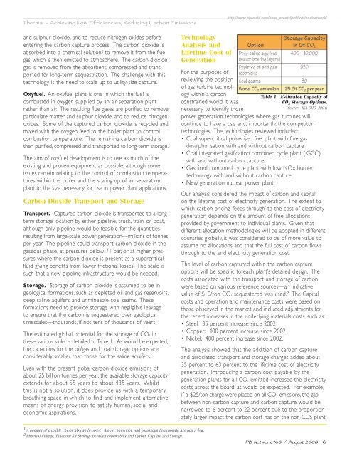
The estimated global potential for the storage of CO2 <strong>in</strong><br />
these various s<strong>in</strong>ks is detailed <strong>in</strong> Table 1. As would be expected,<br />
the capacities for the oil/gas and coal storage options are<br />
considerably smaller than those for the sal<strong>in</strong>e aquifers.<br />
Even with the present global carbon dioxide emissions of<br />
about 25 billion tonnes per year, the available storage capacity<br />
extends for about 55 years to about 435 years. Whilst<br />
this is not a solution, it does provide us with a temporary<br />
breath<strong>in</strong>g space <strong>in</strong> which to f<strong>in</strong>d and implement alternative<br />
means of energy provision to satisfy human, social and<br />
economic aspirations.<br />
Technology<br />
Analysis and<br />
Lifetime Cost of<br />
Generation<br />
For the purposes of<br />
review<strong>in</strong>g the position<br />
of gas turb<strong>in</strong>e technology<br />
with<strong>in</strong> a carbon<br />
constra<strong>in</strong>ed world, it was<br />
necessary to identify those<br />
power generation technologies where gas turb<strong>in</strong>es will<br />
cont<strong>in</strong>ue to have a use and, importantly, the competitor<br />
technologies. The technologies reviewed <strong>in</strong>cluded:<br />
• Coal supercritical pulverised fuel plant with flue gas<br />
desulphurisation with and without carbon capture<br />
• Coal <strong>in</strong>tegrated gasification comb<strong>in</strong>ed cycle plant (IGCC)<br />
with and without carbon capture<br />
• Gas fired comb<strong>in</strong>ed cycle plant with low NOx burner<br />
technology with and without carbon capture<br />
• New generation nuclear power plant.<br />
Table 1: Estimated Capacity of<br />
CO 2 Storage Options.<br />
(Source: IEA-GHG, 2004)<br />
Our analysis considered the impact of carbon and capital<br />
on the lifetime cost of electricity generation. The extent to<br />
which carbon pric<strong>in</strong>g ‘feeds through’ to the cost of electricity<br />
generation depends on the amount of free allocations<br />
provided by government to <strong>in</strong>dividual plants. Given that<br />
different allocation methodologies will be adopted <strong>in</strong> different<br />
countries globally, it was considered to be of more value to<br />
assume no allocations and that the full cost of carbon flows<br />
through to the end electricity generation cost.<br />
The level of carbon captured with<strong>in</strong> the carbon capture<br />
options will be specific to each plant’s detailed design. The<br />
costs associated with the transport and storage of carbon<br />
were based on various reference sources—an <strong>in</strong>dicative<br />
value of $10/ton CO2 sequestered was used. 2 The Capital<br />
costs and operation and ma<strong>in</strong>tenance costs were based on<br />
those observed <strong>in</strong> the market and <strong>in</strong>cluded adjustments for<br />
the recent <strong>in</strong>creases <strong>in</strong> the underly<strong>in</strong>g materials costs, such as:<br />
• Steel: 35 percent <strong>in</strong>crease s<strong>in</strong>ce 2002<br />
• Copper: 400 percent <strong>in</strong>crease s<strong>in</strong>ce 2002<br />
• Nickel: 400 percent <strong>in</strong>crease s<strong>in</strong>ce 2002.<br />
The analysis showed that the addition of carbon capture<br />
and associated transport and storage charges added about<br />
35 percent to 63 percent to the lifetime cost of electricity<br />
generation. Introduc<strong>in</strong>g a carbon cost payable by the<br />
generation plants for all CO2 emitted <strong>in</strong>creased the electricity<br />
costs across the board, as would be expected. For example,<br />
if a $25/ton charge were placed on all CO2 emissions, the gap<br />
between non-carbon capture and carbon capture would be<br />
narrowed to 6 percent to 22 percent due to the proportionately<br />
larger impact the carbon cost has on the non-CCS plant.<br />
1 A number of possible chemicals can be used. Am<strong>in</strong>e, ammonia, and potassium bicarbonate are just a few.<br />
2 Imperial College, Potential for Synergy between renewables and Carbon Capture and Storage.<br />
PB Network #68 / August 2008 6