

High-Torque Stepper Motor PKP Series - Oriental Motor
High-Torque Stepper Motor PKP Series - Oriental Motor
High-Torque Stepper Motor PKP Series - Oriental Motor

You also want an ePaper? Increase the reach of your titles
YUMPU automatically turns print PDFs into web optimized ePapers that Google loves.
■General Specifications<br />
Heat-Resistant Class<br />
Insulation Resistance<br />
Dielectric Strength<br />
Operating Environment<br />
(In operation)<br />
Temperature Rise<br />
Item<br />
Ambient Temperature<br />
Ambient Humidity<br />
Atmosphere<br />
Stop Position Accuracy ✽1<br />
Shaft Runout<br />
Radial Play ✽2<br />
Axial Play ✽3<br />
Concentricity of Installing Pilot to the Shaft<br />
Perpendicularity of Installation Surface to the Shaft<br />
Specifi cation<br />
130 (B)<br />
100 MΩ or more when 500 VDC megger is applied between the windings and the case under normal ambient temperature and humidity.<br />
Suffi cient to withstand 1.0 kVAC at 60Hz applied between the windings and the case for 1 minute, under normal ambient temperature and<br />
humidity.<br />
(0.5 kV for models with a frame size of 42 mm (1.65 in.))<br />
−10∼+50˚C (+14∼+122˚F) (non-freezing)<br />
85% max. (non-condensing)<br />
No corrosive gases or dust. The product should not be exposed to water, oil or other liquids.<br />
· Bipolar and Unipolar, <strong>PKP</strong>21□, <strong>PKP</strong>22□, <strong>PKP</strong>23□, <strong>PKP</strong>243, <strong>PKP</strong>244, <strong>PKP</strong>245, <strong>PKP</strong>246, <strong>PKP</strong>26□ and SH<br />
geared type: Temperature rise of the windings is 80˚C (176˚F) or less (measured by the resistance change method) at the rated voltage,<br />
at standstill, and 2-phases excited.<br />
The following motors are measured with a radiation plate (material aluminum).<br />
<strong>PKP</strong>22□ and <strong>PKP</strong>23□: 115×115×5 mm (4.53×4.53×0.20 in.)<br />
<strong>PKP</strong>244 and <strong>PKP</strong>246: 175×175×5 mm (6.89×6.89×0.20 in.)<br />
<strong>PKP</strong>26□:<br />
250×250×10mm (9.84×9.84×0.39 in.)<br />
±3 arc minutes (±0.05˚) [<strong>PKP</strong>21□: ±5 arc minutes (±0.083˚)]<br />
0.05 mm (0.002 in.) T.I.R. ✽4<br />
0.025 mm (0.001 in.) maximum (load 5 N (1.12 lb.))<br />
0.075 mm (0.003 in.) maximum (load 10 N (2.2 lb.))<br />
0.075 mm (0.003 in.) T.I.R. ✽4<br />
0.075 mm (0.003 in.) T.I.R. ✽4<br />
✽1 This value is for full step under no load. (The value changes with the size of the load.)<br />
✽2 Radial Play: Displacement in shaft position in the radial direction when a 5 N (1.12 lb.) load is applied in the vertical direction to the tip of the motor shaft.<br />
✽3 Axial Play: Displacement in shaft position in the axial direction when a 10 N (2.2 lb.) load is applied to the motor shaft in the axial direction.<br />
✽4 T. I. R. (Total Indicator Reading): The total dial gauge reading when the measurement section is rotated one revolution centered on the reference axis center.<br />
Note<br />
●Do not measure insulation resistance or perform the dielectric strength test while the motor and driver are connected.<br />
ϕ0.075<br />
A<br />
0.05<br />
A<br />
0.075<br />
A<br />
■Permissible Overhung Load and Permissible Thrust Load<br />
Permissible Overhung Load<br />
Type <strong>Motor</strong> Frame Size Applicable Product Gear Ratio<br />
Distance from Shaft End mm [in.]<br />
0 [0] 5 [0.2] 10 [0.39] 15 [0.59] 20 [0.79]<br />
20 mm (0.79 in.) <strong>PKP</strong>213, <strong>PKP</strong>214<br />
12 (2.7) 15 (3.3) − − −<br />
28 mm (1.10 in.) <strong>PKP</strong>223, <strong>PKP</strong>224, <strong>PKP</strong>225 25 (5.6) 34 (7.6) 52 (11.7) − −<br />
35 mm (1.38 in.) <strong>PKP</strong>233, <strong>PKP</strong>235 −<br />
20 (4.5) 25 (5.6) 34 (7.6) 52 (11.7) −<br />
Standard<br />
Type<br />
SH Geared<br />
Type<br />
42 mm (1.65 in.) <strong>PKP</strong>243, <strong>PKP</strong>244, <strong>PKP</strong>245, <strong>PKP</strong>246 20 (4.5) 25 (5.6) 34 (7.6) 52 (11.7) −<br />
56.4 mm (2.22 in.) <strong>PKP</strong>264, <strong>PKP</strong>266, <strong>PKP</strong>268 61 (13.7) 73 (16.4) 90 (20.2) 110 (24.7) 160 (36)<br />
Unit = N (lb.)<br />
Permissible<br />
Thrust Load<br />
<strong>Motor</strong> Mass<br />
or Less<br />
28 mm (1.10 in.) <strong>PKP</strong>223 7.2, 9, 10, 18, 36 15 (3.3) 17 (3.8) 20 (4.5) 23 (5.1) − 10 (2.2)<br />
42 mm (1.65 in.) <strong>PKP</strong>243 3.6, 7.2, 9, 10, 18, 36 10 (2.2) 15 (3.3) 20 (4.5) 30 (6.7) − 15 (3.3)<br />
60 mm (2.36 in.) <strong>PKP</strong>264<br />
3.6, 7.2, 9, 10 30 (6.7) 40 (9) 50 (11.2) 60 (13.5) 70 (15.7)<br />
18, 36 80 (18) 100 (22) 120 (27) 140 (31) 160 (36)<br />
30 (6.7)<br />
●The applicable motor products are listed such that the motor can be determined.<br />
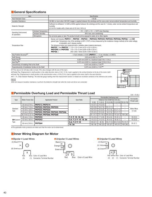
■Inner Wiring Diagram for <strong>Motor</strong><br />
●Bipolar 4 Lead Wires<br />
(4) Black<br />
(6) Green<br />
A<br />
Red<br />
(3)<br />
B<br />
Blue<br />
(1)<br />
Color of Lead Wire<br />
Connector Terminal Number<br />
●Unipolar 5 Lead Wires<br />
Black<br />
Orange<br />
Green<br />
A A<br />
B B<br />
Red Blue Color of Lead Wire<br />
●Unipolar 6 Lead Wires<br />
(4) Black<br />
(5) Yellow<br />
(6) Green<br />
A A<br />
Red<br />
(3)<br />
B<br />
B<br />
White Blue<br />
(2) (1)<br />
Color of Lead Wire<br />
Connector Terminal Number<br />
40


