PEL-60-60-10 - Physical Instruments
PEL-60-60-10 - Physical Instruments
PEL-60-60-10 - Physical Instruments

You also want an ePaper? Increase the reach of your titles
YUMPU automatically turns print PDFs into web optimized ePapers that Google loves.
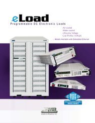
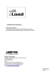
Operation Manual<br />
<strong>PEL</strong>-<strong>60</strong>-<strong>60</strong>-<strong>10</strong><br />
Programmable DC Electronic Load<br />
This manual covers model:<br />
<strong>PEL</strong><strong>60</strong>-<strong>60</strong>-<strong>10</strong><br />
Contact Information<br />
Telephone: 800 733 5427 (toll free in North America)<br />
858 450 0085 (direct)<br />
Fax: 858 458 0267<br />
Email:<br />
Domestic Sales: domorders.sd@ametek.com<br />
International Sales: intlorders.sd@ametek.com<br />
Customer Service: service.ppd@ametek.com<br />
Web: www.programmablepower.com<br />
1 M470030-01 Rev A
______________________________________________________________________________________________<br />
WARRANTY INFORMATION<br />
CERTIFICATION<br />
AMETEK Programmable Power, Inc. (“AMETEK”), certifies that this product met its published specifications at<br />
time of shipment from the factory.<br />
Contact Information<br />
Telephone: 800 733 5427 (toll free in North America)<br />
858 450 0085 (direct)<br />
Fax: 858 458 0267<br />
Email:<br />
Domestic Sales: domorders.sd@ametek.com<br />
International Sales: intlorders.sd@ametek.com<br />
Customer Service: service.ppd@ametek.com<br />
Web: www.programmablepower.com<br />
Warranty Period:<br />
AMETEK DC Loads: One Year<br />
WARRANTY TERMS<br />
AMETEK Programmable Power, Inc. (“AMETEK”), provides this written warranty covering the<br />
Product stated above, and if the Buyer discovers and notifies AMETEK in writing of any defect in<br />
material or workmanship within the applicable warranty period stated above, then AMETEK may,<br />
at its option: repair or replace the Product; or issue a credit note for the defective Product; or<br />
provide the Buyer with replacement parts for the Product.<br />
The Buyer will, at its expense, return the defective Product or parts thereof to AMETEK in<br />
accordance with the return procedure specified below. AMETEK will, at its expense, deliver the<br />
repaired or replaced Product or parts to the Buyer. Any warranty of AMETEK will not apply if the<br />
Buyer is in default under the Purchase Order Agreement or where the Product or any part<br />
thereof:<br />
• is damaged by misuse, accident, negligence or failure to maintain the same as<br />
specified or required by AMETEK;<br />
• is damaged by modifications, alterations or attachments thereto which are not<br />
authorized by AMETEK;<br />
• is installed or operated contrary to the instructions of AMETEK;<br />
• is opened, modified or disassembled in any way without AMETEK’s consent; or<br />
• is used in combination with items, articles or materials not authorized by AMETEK.<br />
The Buyer may not assert any claim that the Products are not in conformity with any warranty<br />
until the Buyer has made all payments to AMETEK provided for in the Purchase Order Agreement.<br />
PRODUCT RETURN PROCEDURE<br />
1. Request a Return Material Authorization (RMA) number from the repair facility (must be<br />
done in the country in which it was purchased):<br />
• In the USA, contact the AMETEK Repair Department prior to the return of the<br />
product to AMETEK for repair:<br />
Telephone: 800-733-5427 (toll free North America)<br />
858-450-0085 (direct)<br />
• Outside the United States, contact the nearest Authorized Service Center<br />
(ASC). A full listing can be found either through your local distributor or our<br />
website, www.programmablepower.com, by clicking Support and going to the<br />
Service Centers tab.<br />
2. When requesting an RMA, have the following information ready:<br />
• Model number<br />
• Serial number<br />
• Description of the problem<br />
NOTE: Unauthorized returns will not be accepted and will be returned at the shipper’s expense.<br />
NOTE: A returned product found upon inspection by AMETEK, to be in specification is subject to<br />
an evaluation fee and applicable freight charges.<br />
2 M470030-01 Rev A
About AMETEK<br />
AMETEK Programmable Power, Inc., a Division of AMETEK, Inc., is a global leader in the design and<br />
manufacture of precision, programmable power supplies for R&D, test and measurement, process control,<br />
power bus simulation and power conditioning applications across diverse industrial segments. From bench<br />
top supplies to rack-mounted industrial power subsystems, AMETEK Programmable Power is the proud<br />
manufacturer of AMETEK brand power supplies.<br />
AMETEK, Inc. is a leading global manufacturer of electronic instruments and electromechanical devices<br />
with annualized sales of $2.5 billion. The Company has over 11,000 colleagues working at more than 80<br />
manufacturing facilities and more than 80 sales and service centers in the United States and around the<br />
world.<br />
Trademarks<br />
AMETEK is a registered trademark of AMETEK, Inc. AMETEK is a trademark owned by AMETEK, Inc. Other<br />
trademarks, registered trademarks, and product names are the property of their respective owners and<br />
are used herein for identification purposes only.<br />
Notice of Copyright<br />
Manual © 2003-2011 AMETEK Programmable Power, Inc. All rights reserved.<br />
Exclusion for Documentation<br />
UNLESS SPECIFICALLY AGREED TO IN WRITING, AMETEK PROGRAMMABLE POWER, INC.<br />
(“AMETEK”):<br />
(a) MAKES NO WARRANTY AS TO THE ACCURACY, SUFFICIENCY OR SUITABILITY OF ANY TECHNICAL<br />
OR OTHER INFORMATION PROVIDED IN ITS MANUALS OR OTHER DOCUMENTATION.<br />
(b) ASSUMES NO RESPONSIBILITY OR LIABILITY FOR LOSSES, DAMAGES, COSTS OR EXPENSES,<br />
WHETHER SPECIAL, DIRECT, INDIRECT, CONSEQUENTIAL OR INCIDENTAL, WHICH MIGHT ARISE OUT<br />
OF THE USE OF SUCH INFORMATION. THE USE OF ANY SUCH INFORMATION WILL BE ENTIRELY AT THE<br />
USER’S RISK, AND<br />
(c) REMINDS YOU THAT IF THIS MANUAL IS IN ANY LANGUAGE OTHER THAN ENGLISH, ALTHOUGH<br />
STEPS HAVE BEEN TAKEN TO MAINTAIN THE ACCURACY OF THE TRANSLATION, THE ACCURACY<br />
CANNOT BE GUARANTEED. APPROVED AMETEK CONTENT IS CONTAINED WITH THE ENGLISH<br />
LANGUAGE VERSION, WHICH IS POSTED AT WWW.PROGRAMMABLEPOWER.COM.<br />
Date and Revision<br />
March, 2011, Rev A<br />
Part Number<br />
XXXXXXX-XX<br />
Contact Information<br />
Telephone: 800 733 5427 (toll free in North America) 858 450 0085 (direct)<br />
Fax: 858 458 0267<br />
Email:<br />
Domestic Sales : domorders.sd@ametek.com<br />
International Sales : intlorders.sd@ametek.com<br />
Customer Service : service.ppd@ametek.com<br />
Web: www.programmablepower.com<br />
3 M470030-01 Rev A
_________________________________________________________________________________________<br />
SAFETY SUMMARY<br />
: The following general safety precautions must be observed during all phases of operation of this<br />
instrument. Failure to comply with these precautions or with specific warnings elsewhere in this manual violates<br />
safety standards of design, manufacture, and intended use of the instrument. AMETEK Programmable Power, Inc.<br />
assumes no liability for the customer’s failure to comply with these requirements.<br />
WARNING<br />
Servicing instructions are for use by service-trained personnel. To avoid dangerous electrical shock, do not perform<br />
any servicing unless you are qualified to do so. Some procedures described in this manual are performed with power<br />
supplied to the instrument while its protective covers are removed. If contacted, the energy available at many points<br />
may result in personal injury.<br />
ENVIRONMENTAL CONDITIONS<br />
This instrument is intended for indoor use in an installation category II, pollution degree 2 environment. It is<br />
designed to operate at maximum relative humility of 95% and at altitudes of up to 2000 meters. Refer to the<br />
specifications for the ac mains voltage requirements and ambient operating temperature range.<br />
BEFORE APPLYING POWER<br />
Verify that the product is set to the appropriate line voltage, the correct line fuse is installed, and all safety<br />
precautions are taken.<br />
GROUND THE INSTRUMENT<br />
Before switching on the instrument, the protective earth terminal of the instrument must be connected to the<br />
protective conductor of the main power cord. The mains plug shall be inserted only in an outlet socket that is<br />
provided with a protective earth contact. This protective action must not be negated by the use of an extension cord<br />
that does not have a protective conductor. Any interruption of the protective grounding or disconnection of the<br />
protective earth terminal will cause a potential shock hazard that could result in personal injury.<br />
FUSES<br />
Only fuses with the required rated current, voltage, and specified type should be used. Do not use repaired fuses or<br />
short-circuited fuse holder. To do so could cause a shock or fire hazard.<br />
AVOID ACCESS TO LIVE CIRCUITS<br />
Operating personnel must not remove the instrument cover. Component replacement and internal adjustments must<br />
be made by qualified service personnel. Do not replace components with the power cable connected. Under certain<br />
conditions, dangerous voltage may exits even with the power cable removed, to avoid injuries, always disconnect<br />
power, discharge circuits and remove external voltage sources before touching components.<br />
AVOID TROUBLESHOOTING ALONE<br />
Do not attempt internal service or adjustment unless another person, capable of rendering first aid and resuscitation,<br />
is present. Any adjustment, maintenance, and repair of this instrument while it is opened and under voltage should be<br />
avoided as much as possible. If this is unavoidable, adjustment, maintenance, and repair should be carried out by<br />
only qualified personnel who are aware of the hazard involved.<br />
DO NOT SUBSTITUTE PARTS OR MODIFY INSTRUMENT<br />
Because of the danger of introducing additional hazards, do not install substitute parts or perform an unauthorized<br />
modification to the instrument. Return the instrument to an American Reliance Service Department for service and<br />
repair to ensure that safety features are maintained.<br />
4 M470030-01 Rev A
SAFETY SYMBOLS<br />
WARNING The WARNING symbol denotes a hazard. It calls attention to a procedure, practice, or the like,<br />
which, if not correctly performed or adhered to, could result in personal injury. Do not proceed beyond a<br />
WARNING symbol until the indicated conditions are fully understood and met.<br />
CAUTION The CAUTION symbol denotes a hazard. It calls attention to an operating procedure, or the like,<br />
which, if not correctly performed or adhered to, could result in damage to or destruction of parts or all of the<br />
products. Do not proceed beyond a CAUTION symbol until the indicated conditions are fully understood and met.<br />
SAFETY SYMBOL DEFINITIONS<br />
Symbol Description<br />
------------------------------------------------------------------------------------------------------------<br />
Direct current.<br />
Alternating current.<br />
Both direct and alternating current.<br />
Earth (ground) terminal.<br />
Protective earth (ground) terminal.<br />
Terminal for Neutral conductor on permanently installed equipment.<br />
Terminal for Line conductor on permanently installed equipment.<br />
Standby (supply)<br />
Units with this symbol are not completely disconnect the unit from AC<br />
mains, either disconnect the power cord or have a qualified electrician<br />
install an external switch.<br />
Warning, risk of electric shock.<br />
Caution (refer to accompanying documents).<br />
5 M470030-01 Rev A
CONTENTS<br />
ONE: FEATURES AND SPECIFICATION 8<br />
INTRODUCTION 8<br />
FEATURES AND OPTIONS 8<br />
FRONT PANEL CONTROLS 9<br />
FRONT PANEL FEATURES 9<br />
FRONT PANEL KEYPAD <strong>10</strong><br />
FRONT KEYPAD DEFINITIONS <strong>10</strong><br />
LCD STATUS ENUNCIATOR 11<br />
LCD DESCRIPTION 11<br />
REAR PANEL CONNECTORS 12<br />
REAR PANEL FEATURES 12<br />
EXTERNAL PROGRAMMING PORT 13<br />
SPECIFICATION 14<br />
INPUT VOLTAGE LIMIT 15<br />
INPUT CURRENT LIMIT 15<br />
INPUT POWER LIMIT 15<br />
AIRFLOW FUNCTION 16<br />
DIMENSIONAL DRAWING 17<br />
TWO: INSTALLATION 18<br />
INTRODUCTION 18<br />
BASIC SET UP PROCEDURE 18<br />
INSPECTION, CLEANNING, AND PACKAGING 19<br />
RETURNING ELECTRONIC LOAD TO THE MANUFACTURER 19<br />
PACKAGING FOR SHIPPING OR STORAGE 20<br />
LOCATION, MOUNTING, AND VENTILATION 20<br />
FUSE REPLACEMENT 21<br />
AC INPUT POWER CONNECTION 21<br />
AC INPUT CONNECTOR AND VOLTAGE SELECTION 21<br />
AC INPUT CORD 22<br />
LOAD WIRING 22<br />
LOAD WIRING LENGTH FOR OPERATION WITH SENSE LINES 23<br />
NOISE AND IMPEDANCE EFFECTS 23<br />
LOAD CONNECTIONS 23<br />
INPUT TERMINAL 23<br />
INPUT TERMINAL CONNECTOR 23<br />
LOCAL SENSE CONFIGURATION 24<br />
REMOTE SENSE CONFIGURATION 25<br />
PARALLEL CONNECTION 26<br />
TRIGGER OPERATION 27<br />
ZERO-VOLT LOADING CONNECTION 27<br />
THREE: LOCAL OPERATION 28<br />
INTRODUCTION 28<br />
VOLTAGE AND CURRENT METERING INFORMATION 28<br />
OPERATING STATUS INFORMATION 29<br />
LOCAL AND GPIB OPERATION INFORMATION 30<br />
MODE MENU OPERATION AND RANGE SETTING 30<br />
MAIN LEVEL LOCAL OPERATION 31<br />
SPECIAL EDITING KEYS 32<br />
UTILITY MENU FUNCTION 32<br />
FUNCTION MENU REFERENCE 35<br />
SYSTEM FUNCTION 35<br />
GPIB FUNCTION 36<br />
RS-232 FUNCTION 37<br />
MAX/MIN SETTING FUNCTION 38<br />
6 M470030-01 Rev A
STEPPING OPERATION SET-UP 38<br />
STEPPING FUNCTION 38<br />
STEP NUMBER 39<br />
ENTERING STEPPING MODE VALUE 39<br />
PROTECTION FUNCTION 40<br />
RECORD FUNCTION 40<br />
PROGRAMMING POINTS 41<br />
LOOP NUMBER 41<br />
TIME DURATION 42<br />
ENTERING TRANSIENT MODE VALUES 42<br />
TRANSIENT FREQUENCY, SLEW RATE AND DUTY CYCLE PROGRAMMING 43<br />
TRANSIENT MODE 44<br />
LOCAL TRANSIENT OPERATION 44<br />
CONTINUOUS MODE 44<br />
STEPPING MODE 45<br />
PULSE MODE 45<br />
TOGGLE MODE 46<br />
FOUR: REMOTE OPERATION 47<br />
INTRODUCTION 47<br />
INTRODUCTION TO GPIB & RS-232 (SCPI) COMMANDS 47<br />
OVER VIEW SCPI LANGUAGE 48<br />
LANGUAGE DICTIONARY 49<br />
COMMANDS STRUCTURE 49<br />
SCPI (GPIB & RS-232) PROGRAMMING COMMANDS SET 50<br />
COMMON COMMANDS 59<br />
COMMON LIST <strong>60</strong><br />
FIVE: CALIBRATION 62<br />
INTRODUCTION 62<br />
CALIBRATION SERVICE ENVIRONMENT AND PRECAUTIONS 62<br />
CALIBRATION REQUIRED EQUIPMENT 63<br />
CALIBRATION PARAMETERS 64<br />
LOCAL CALIBRATION PROCEDURES 64<br />
RE-INSTALLING CALIBRATION DATA 72<br />
7 M470030-01 Rev A
ONE: FEATURES AND SPECIFICATION<br />
INTRODUCTION<br />
This <strong>PEL</strong> Series Programmable DC Electronic Load from AMETEK Programmable Power, Inc. offers a complete<br />
solution to the electronic load system requirements. This instrument was designed to assist in the development and<br />
testing of new products, as well as is being a standard instrument for automatic test systems and evaluation of dc<br />
power supplies, batteries, and power components. Other applications include use as a power circuit breaker or<br />
crowbar, high current function or pulse generator, fuel-cell and photovoltaic cell test, and de-energizing super<br />
conducting magnets. This instrument uses advanced power MOSFETs to dissipate the input power. The electronic<br />
load consumes minimum power to control maximum input power handling capability. Complex circuits are used to<br />
control the power balance and dissipation of the MOSFET. This control circuit also supports the Constant Voltage<br />
(CV), Constant Current (CC), Constant Resistance (CR), and Constant Power (CP) modes of operation. It comes<br />
with Standard Commands for Programmable Instrument (SCPI) commands, remote monitoring of input voltage and<br />
currents is a standard features. Use this electronic load can be used either on your bench or in a standard 19 in. (483<br />
mm) rack: The programming electronic load occupies 6.968 in. (4 U) of vertical rack space. Designed for<br />
continuous use in standalone or systems applications, this electronic load is typically used to evaluate DC equipment,<br />
control circuits, or burn-in power applications.<br />
TABLE 1.1 GENERAL VOLTAGE AND CURRENT RANGES<br />
Model Voltage Input Range Current Input Range<br />
<strong>PEL</strong><strong>60</strong>-<strong>60</strong>-<strong>10</strong> <strong>60</strong> Vmax <strong>10</strong> Amax<br />
FEATURES AND OPTIONS<br />
• Four constant operating modes: Constant current (CC), constant voltage (CV), constant resistance (CR),<br />
and constant current (CP) mode operation.<br />
• Local control and remote programming for plus amplitude, pulse width, and pulse cycle.<br />
• Trig-In/Trig-Out and measurement functions.<br />
• GPIB and RS-232 interface programming with SCPI command language.<br />
• Front panel control with keypad.<br />
• Built in pulse generator for continuous, pulsed, and toggled transient operation.<br />
• Six programmable protection modes: Over Voltage Protection (OVP), Under Voltage Protection (UVP),<br />
Over Current Protection (OCP), Under Current Protection (UCP), Over Power Protection (OPP), and Under<br />
Power Protection (UPP).<br />
• Fan speed control for reduced acoustic noise under light load conditions.<br />
• 256 Real-time voltage, current, power recording capability with programmable timer setup.<br />
• 99 point voltage, current and power self-programming capability from front panel keypad.<br />
• “C” Operand for battery testing.<br />
• 0-<strong>10</strong>Vdc analog programmable.<br />
• Dual-mode transient generator.<br />
• 256 step programmable slew rate capability.<br />
• Simple closed-case calibration.<br />
8 M470030-01 Rev A
FRONT PANEL CONTROLS<br />
1<br />
2<br />
3<br />
Use this Figure 1.1 to familiarize your self with this instrument.<br />
See next page for keypad definition.<br />
FIGURE 1.1 FRONT PANEL<br />
FRONT PANEL FEATURES<br />
1. Front panel Liquid Crystal Display (LCD) module.<br />
2. Front panel keypad.<br />
3. Power ON/OFF switch.<br />
9 M470030-01 Rev A
FRONT PANEL KEYPAD<br />
MAIN TRANS UTILIY<br />
CV 7<br />
TIME<br />
8<br />
VALUE<br />
9 LOCAL<br />
STEP <br />
CC 4 5 6 MODE<br />
TR ON/OFF<br />
<br />
CR 1 2 3 FUNC<br />
INPUT ON/OFF<br />
SHORT ON/OFF<br />
CP 0 • CLEAR ENTER<br />
FIGURE 1.2 FRONT PANEL KEYPAD<br />
FRONT KEYPAD DEFINITIONS<br />
Key “0” Numeric entry key for number 0. Enables the Constant Power mode and INPUT ON/OFF toggle key.<br />
INPUT ON/OFF key also activates the recording capability when recording time is greater than 0<br />
(zero).<br />
Key “.”<br />
Key “1”<br />
Key “2”<br />
Key “3”<br />
Numeric entry key for decimal dot. Enables SHORT ON/OFF, toggle key.<br />
Numeric entry key for number 1. Enables Constant Resistance mode of operating, TR transient<br />
enable key, and ST stepping enable key.<br />
Numeric entry key for number 2. Step Down key to decrease the step number in the stepping<br />
program function.<br />
Numeric entry key for number 3. Pressing #3 key.<br />
Key “4” Numeric entry key for number 4. Constant Current mode enable key and the Left Shift key .<br />
Key “5”<br />
Key “6”<br />
Key “7”<br />
Key “8”<br />
Key “9”<br />
Numeric entry key for number 5. STEP function key for step editing mode.<br />
Numeric entry key for number 6. Right Shift key.<br />
Numeric entry key for number 7. Constant Voltage mode enable key. MAIN programming<br />
level entry key and TIME programming key in the step function operation.<br />
Numeric entry key for number 8. Step Up key to increase step number in stepping<br />
programming function.<br />
Numeric entry key for number 9. TRANS transient programming level entry key and VALUE<br />
setting in the step function operation.<br />
Key “CLEAR” Clears partially set commands and return the unit to the metering mode. By pressing the<br />
"Clear" with no entry will display "AMREL Model number and software version.<br />
Key “MODE” Enable CV/CC/CR/CP operating mode.<br />
Key “LOCAL” Returns the GPIB or RS-232 mode to local operations. Enable the system utility and allows GPIB,<br />
RS-232, Calibration, and System operation parameter and setting to be changed. Pressing the<br />
LOCAL key will change status from RMT to LCL (local operation).<br />
Key “FUNC”<br />
Allows programming value settings for Frequency, Duty cycle and Slew rate for Transient mode<br />
operation.<br />
Key “ENTER” Enters the values in the set mode and returns the unit to the metering mode.<br />
<strong>10</strong> M470030-01 Rev A
LCD STATUS ENUNCIATOR<br />
LIQUID CRYSTAL DISPLAY:<br />
1<br />
2 3<br />
PROGRAMMABLE ELECTRONIC LOAD<br />
CV<br />
CC<br />
CR<br />
CP<br />
<br />
L<br />
0.0001V 0.0001A<br />
OFF OVP TOG<br />
1 2 3 4 5 6 7 8<br />
RNG INPUT PROT STS<br />
<br />
LCL<br />
RMT<br />
4 5<br />
6<br />
7<br />
8<br />
FIGURE 1.3 LIQUID CRYSTAL DISPLAY<br />
The LCD displays real time input Voltage/Current & mode status. These messages are viewed in either<br />
local or remote mode.<br />
LCD DESCRIPTION<br />
1. Mode indicator: Constant Voltage (CV), Constant Current (CC), Constant Resistor (CR), and<br />
Constant Power (CP).<br />
2. Voltage reading indicator.<br />
3. Current reading indicator.<br />
4. RNG operating range indicator: Low range (L), Middle range (M), and High range (H).<br />
5. INPUT ON/OFF.<br />
6. PROT operating protection indicator: (Un-regular (UNR), Over/Under Voltage Protection (OVP/UVP),<br />
Over/Under Current Protection (OCP/UCP), Over/Under Power Protection (OPP/UPP), and Over Temperature<br />
Protection (OTP).<br />
7. STS operating status indicator: Transient Mode (TRAN), Toggle Mode (TOG), Stepping Mode (STEP),<br />
Pulse Mode (PULS), and Short Mode (SHT)<br />
8. Local mode (LCL) / Remote mode (RMT) indicator.<br />
11 M470030-01 Rev A
REAR PANEL CONNECTORS<br />
1 6 7<br />
2<br />
8<br />
3<br />
5<br />
4<br />
FIGURE 1.4 REAR PANEL<br />
REAR PANEL FEATURES<br />
1. AC power inlet.<br />
2. Fuseholder.<br />
3. External programming signal port.<br />
4. Positive input connector.<br />
5. Negative input connector.<br />
6. Chassis / line ground lug screw.<br />
7. 9-pin D-sub male connector for RS232 Interface.<br />
8. Standard GPIB interface connector.<br />
12 M470030-01 Rev A
EXTERNAL PROGRAMMING PORT<br />
The external programming port provides remote sense inputs, input voltage monitoring, input current monitoring,<br />
external trigger input, external trigger output, and analog programming signal.<br />
12 11 <strong>10</strong> 9 8 7 6 5 4 3 2 1<br />
D<br />
G<br />
N<br />
D<br />
T<br />
R<br />
I<br />
G<br />
O<br />
U<br />
T<br />
T<br />
R<br />
I<br />
G<br />
I<br />
N<br />
P<br />
O<br />
R<br />
T<br />
F<br />
A<br />
U<br />
L<br />
T<br />
N<br />
C<br />
I<br />
M<br />
O<br />
N<br />
V<br />
M<br />
O<br />
N<br />
A<br />
N<br />
A<br />
L<br />
O<br />
G<br />
A<br />
G<br />
N<br />
D<br />
-<br />
S<br />
+<br />
S<br />
Pin 1 +S Positive remote sense.<br />
Pin 2 -S Negative remote sense.<br />
Pin 3 AGND Analog Ground. Provides common (reference) connection for external<br />
programming input. When an external programming function is not used,<br />
connect this point to Analog pin 4 to prevent EMI Noise.<br />
Pin 4 ANALOG External analog programming signal. Only in CC mode middle range, the<br />
electronic load can be programmed externally by 0-<strong>10</strong>Volts DC or DC +<br />
AC voltage. When external analog programming function is not used,<br />
connect this point to AGND pin 3 to prevent EMI Noise.<br />
Pin 5 VMON Input voltage monitoring signal. Generates a 0-<strong>10</strong>Volt output signal that is<br />
linearly proportional to the electronic load’s 0 to full-scale voltage.<br />
Pin 6 IMON Input current monitoring signal. Generates a 0-<strong>10</strong>Volt output signal that is<br />
linearly proportional to the electronic load’s 0 to full-scale current.<br />
Pin 7 NC No connection<br />
Pin 8 FAULT Fault signal output. A TTL compatible signal that becomes active (high)<br />
when any of the protections are triggered.<br />
Pin 9 PORT Digital port output. (Not implemented)<br />
Pin <strong>10</strong> TRIGIN External trigger signal input. A TTL compatible signal is used to activate<br />
the electronic load. Trig-in is used to change to a preset mode or switch<br />
between settings in transient mode, generate a pulse in pulse mode, or<br />
trigger the stepping mode.<br />
Pin 11 TRIGOUT External trigger signal output. A TTL compatible signal that is activated<br />
via the Trig-in or GPIB command *TRG. This output follows the state of<br />
the TRIGIN input. External trigger output is used for triggering<br />
oscilloscopes, power supplies, or other electronic loads that have external<br />
trigger input<br />
Pin 12 DGND Digital Ground. Provides the common (reference) connection for Trig-in<br />
and Trig-out.<br />
13 M470030-01 Rev A
SPECIFICATION<br />
The following is the performance specification for the <strong>PEL</strong><strong>60</strong>-<strong>10</strong>-<strong>10</strong>, Programming DC Electronic Load. All<br />
specifications are at the rear terminals with a power source, and local sensing unless otherwise stated.<br />
Specifications are subject to change without notice.<br />
14 M470030-01 Rev A
INPUT VOLTAGE LIMIT<br />
The programming electronic load can handle voltages within nominal values and surge voltages less than <strong>10</strong>% above<br />
nominal value. The Over-voltage protection will be tripped when the input voltage exceeds <strong>10</strong>% of nominal value.<br />
For CV mode application, the input power source should have current limit capability to prevent exceeding the<br />
electronic load’s input current range.<br />
WARNING<br />
Insure that the maximum voltage applied to electronic load will not cause the unit to sink more current and exceed<br />
the power rating. Damage to the power module will occur if the power source is capable of providing more power<br />
than the load can handle.<br />
INPUT CURRENT LIMIT<br />
The nominal current handling capability of the programming electronic load is described in the specification section.<br />
Care should be taken when the Load Bank is operating in the CV mode in order to prevent the load from drawing<br />
more than the maximum current rating. Although, an Over-current circuit to limit the maximum current to less than<br />
<strong>10</strong>% above nominal rated power has been provided, at times the total power may exceed maximum rated power for a<br />
short term only. However, the load will be severely damaged if the total power consumption is continued to operate<br />
above maximum power rating. For CC mode operation, the input power source should have a Constant Voltage<br />
capability to prevent exceeding the loads input power rating.<br />
Three over current protection features have been provided. 1) Over current protection to limit maximum current to<br />
<strong>10</strong>% above nominal value. 2) Software selectable, the user can set and read back the input protection current level. 3)<br />
Each power MOSFET has its own fuse to protect the power module in the worst-case condition.<br />
CAUTION<br />
In the event the over current circuit is not fast enough to limit the input current, a protective fuse for each power<br />
MOSFET is provided and will open if the input surge current exceeds maximum rating.<br />
INPUT POWER LIMIT<br />
The programming electronic load is designed for rated power handling capability within an input voltage of within<br />
the maximum input voltage and input current values as described in the system specification section. Careful<br />
attention should be made to insure that the input power source does not exceed the rated power. Above all, fault or<br />
error precautions need to be taken into consideration to prevent the individual input voltage, current, and/or power<br />
from exceeding the input range settings of the unit<br />
WARNING<br />
Anticipate the Maximum output of the power source carefully and consider the worst-case scenario. The maximum<br />
power range of the load should be higher than the output power of the source.<br />
For CP mode application, the programming electronic load can be set to maximum power dissipation with the<br />
following limitations. Input must be within maximum voltage and current ratings. For example, <strong>PEL</strong><strong>60</strong>-<strong>10</strong>-<strong>10</strong><br />
applied <strong>10</strong>V/<strong>10</strong>A/<strong>60</strong>W. Therefore, the maximum power will be limited to 6V x <strong>10</strong>Amps = <strong>60</strong>W only. Thus, the<br />
limits are set by the hardware's maximum value limit.<br />
15 M470030-01 Rev A
V in<br />
MaxV<br />
Maximum Current – Max A<br />
Maximum Voltage – Max V<br />
Maximum Power – Max KW<br />
LowV<br />
Low-Mid Max A I in<br />
FIGURE 1.5 INPUT VOLTAGE/CURRENT/POWER RELATION DIAGRAM<br />
The theory of the CP operation comes from the divider circuit built in the load. Because of the nonlinear<br />
characteristic of the divider, the input voltage, input current, and power setting will limit the CP mode of operation.<br />
The CP mode will not allow the load to operate beyond the full range of the Constant Power setting.<br />
AIRFLOW FUNCTION<br />
Airflow plays and important part in power dissipation. The programming electronic load uses cooling fans as a<br />
standard cooling system for removing the heat generated from the power module.<br />
Do not impede or obstruct the ventilation holes for any reason to prevent the power components from overheating.<br />
All <strong>PEL</strong>’s have OTP protection to prevent the unit from overheating. The standard programming electronic loads<br />
have forced air-cooling fans installed as the main cooling system and operate when the power-handling unit is turned<br />
on.<br />
16 M470030-01 Rev A
DIMENSIONAL DRAWINGS<br />
(1in. = 25.4mm)<br />
( 4.17 ” )<br />
( 7.01 “ )<br />
( 7.58 “ )<br />
( 21.57 “ )<br />
( 20.47 “ )<br />
17 M470030-01 Rev A
TWO: INSTALLATION<br />
INTRODUCTION<br />
This section provides recommendations and procedures for inspecting, installing, and testing the electronic load.<br />
BASIC SETUP PROCEDURE<br />
Use Table 2.1 to summarize the basic setup procedure and an overall view of the subsections. Use the procedure as a<br />
quick reference if you are familiar with the installation requirements for the programming electronic load. If you<br />
want more information, each step in the procedure refers to subsequent sections, which contain more details. Execute<br />
each step in the sequence provided.<br />
TABLE 2.1 BASIC SETUP PROCEDUE<br />
--------------------------------------------------------------------------------------------------------------------------------------<br />
Step# Description Action Reference<br />
--------------------------------------------------------------------------------------------------------------------------------------<br />
1 Inspection Perform an initial physical Inspection, cleaning,<br />
inspection of the load.<br />
and packaging.<br />
--------------------------------------------------------------------------------------------------------------------------------------<br />
2 Installation Install the instrument on Location, mounting,<br />
bench or rack mount,<br />
and ventilation.<br />
ensuring adequate ventilation.<br />
--------------------------------------------------------------------------------------------------------------------------------------<br />
3 Input power Connect AC input power AC input power<br />
connection.<br />
--------------------------------------------------------------------------------------------------------------------------------------<br />
4 Test Perform functional tests for Functional test.<br />
CV mode, CC mode, and<br />
front panel controls.<br />
--------------------------------------------------------------------------------------------------------------------------------------<br />
5 Source Connect the source. Source connection.<br />
--------------------------------------------------------------------------------------------------------------------------------------<br />
6 Sense Connect sensing lines. Local and Remote sense.<br />
--------------------------------------------------------------------------------------------------------------------------------------<br />
18 M470030-01 Rev A
INSPECTION, CLEANING, AND PACKAGING<br />
• INITIAL INSPECTION: When you first receive your unit, perform a quick physical check.<br />
1. Inspect the instrument for cracks, scratches, broken switches, connectors, and display.<br />
2. Make sure there is not damage on the AC power cord; the AC input cover is installed properly and with the<br />
strain relief.<br />
3. Make sure there is no loose component in the unit that may cause by the long distance shipping.<br />
If the unit is damaged, save all the packing materials and notify the carrier immediately.<br />
• MAINTENANCE: No routine servicing of the electronic load is required except for periodic cleaning.<br />
Whenever the instrument is removed from operation, first use a low pressure air to blow dust from in and<br />
around components on the printed circuit board, clean the front panel with dry cloths or with a weak<br />
solution of soap and water, clean the metal surfaces with naphtha or an equivalent solvent when used in high<br />
humility. Then use the low-pressure air to blow it again.<br />
RETURNING ELECTRONIC LOAD TO THE MANUFACTURER<br />
Return Material Authorization Policy for warranty and non-warranty service:<br />
Before returning a product directly to AMETEK Programmable Power, Inc. you must obtain a Return Material<br />
Authorization (RMA) number and the correct manufactory Ship To: address. Products must also be shipped prepaid.<br />
Product shipments will be refused and returned at sender expense if they are unauthorized shipped without RMA #<br />
clearly marked on the outside of the shipping box, shipped “COD”, or if they are shipped to the wrong location.<br />
Please have the following information when contacting American Reliance for RMA #:<br />
1- The model number of your product.<br />
2- The serial number of your product.<br />
3- Information about the failure and/or reason for the return.<br />
4- A copy of your dated proof of purchase.<br />
When returning the product to AMETEK Programmable Power, Inc.:<br />
1- Package the unit safely, preferably using the original box and packing materials. Please ensure that your<br />
product is shipped fully insured in the original packaging or equivalent. THIS WARRANTY WILL NOT<br />
APPLY WHERE THE PRODUCT IS DAMAGED DUE TO IMPROPER PACKAGING.<br />
2- Include the following information:<br />
o<br />
o<br />
o<br />
o<br />
The RMA# supplied by AMETEK Programmable Power, Inc. clearly marked on the outside of the<br />
box.<br />
A return address where the unit can be shipped. Post office boxes are not acceptable.<br />
A contact person, telephone, email where sender can be reached during work hours.<br />
A brief description of the problem.<br />
Ship the unit prepaid to the address provided by AMETEK customer service representative.<br />
If you are returning a product from outside of the United States:<br />
In addition to the above, you must include return freight funds if you instrument is out of warranty and are<br />
fully responsible for all documents, duties, tariff, and deposits.<br />
19 M470030-01 Rev A
PACKAGING FOR SHIPPING OR STORAGE<br />
Instructions to prepare the instrument for shipping or storage.<br />
1- When returning the unit or sending it to the service center, attach a tag to the unit stating its model number<br />
(available at the front panel label) and its serial number (available at the rear panel label). Give the date of<br />
purchase and an invoice number, if you have it, as well as a brief description of the problem.<br />
2- For storage or shipping, repack the electronic load in its original box. If the original box is not available,<br />
seal the instrument in a plastic bag and pack it in a 200 lb. (90Kg) test corrugated cardboard carton large<br />
enough allow 3 inches (76.2mm) of cushioning material to surround the unit or use a material such as foam<br />
slabs or chips or an appropriate wooden crate used. Please consult with AMETEK shipping department for<br />
proper packing material and handling.<br />
3- Label the package as shown in Figure 2.1.<br />
4- Mark the address of the service center and your return address carton.<br />
5- For storing, no more than two cartons high. The storage temperature should be between -40°C to 70°C.<br />
PROGRAMMABLE DC ELECTRONIC LOAD<br />
Model #: _______________________<br />
Serial #: _______________________<br />
FRAGILE – ELECTRONIC EQUIPMENT<br />
(PLEASE HANDLE WITH CARE)<br />
FIGURE 2.1 SHIPPING OR STORAGE PACKAGE LABEL<br />
LOCATION, MOUNTING, AND VENTILATION<br />
Electronic load is designed for rack-mounted or bench top applications.<br />
RACK MOUNTING INTALLATION:<br />
1- Use the integral rack-mount ears at both sides of the front panel to install the electronic load in a rack mount<br />
application.<br />
2- Provide adequate support for the rear of the instrument without obstructing the ventilation inlets on the sides<br />
and rear of the unit. Use a support bar at the bottom or rear of the unit. Follow the rack-mount<br />
manufacturer’s instructions to install the support bar.<br />
VENTILATION:<br />
Whether you place the electronic load in a rack or on a bench, allow cooling air to reach the ventilation inlets on the<br />
sides of the instrument and allow 4 in. (<strong>10</strong>1.6mm) of unrestricted air space at the rear of the unit for the fan exhaust.<br />
Any ventilation space at the top and bottom of the supply will further lower internal operating temperatures.<br />
20 M470030-01 Rev A
FUSE REPLACEMENT<br />
If the fuse is suspected to be defective, it should be inspected and, if necessary, replaced. To inspect or replace the<br />
fuse, please contact to American Reliance service department before perform the following steps:<br />
(1) Disconnect the AC line cord from the unit to reduce electrical shock hazard.<br />
(2) Remove the fuse by sliding out the fuse holder. The fuse holder is beneath the AC receptacle. Test the fuse<br />
for electrical continuity with an ohmmeter. Other fuse holder located at the printed circuit board.<br />
(3) If the fuse is found to be defective, replace it with a replacement fuse as specified in the following table:<br />
Fuse Rating Specification Location<br />
2Amp, 250V 5 X 20mm (Fast) External Fuse (Beneath the AC receptacle)<br />
(4) Replace the fuse in the fuse holder and re-install.<br />
(5) Re-install the cover and connect the AC power cord.<br />
CAUTION<br />
USE OF ANY FUSE OTHER THAN THE ONE SPECIFIED MAY CAUSE DAMAGE TO THE UNIT,<br />
POSE A SEVERE FIRE HAZARD, AND WILL VOID THE WARRANTY.<br />
AC INPUT POWER CONNECTION<br />
WARNING<br />
JJJJJJ<br />
Disconnect AC power from the instrument before removing the cover. Even with the front panel power switch in the<br />
OFF position, live line voltages are exposed when the cover is removed and the AC cord is attached. Repairs must<br />
be made by experienced service technicians only.<br />
NOTE: You must obtain an authorization from AMETEK first before removing the cover of the instrument.<br />
Otherwise the warranty will be a void.<br />
WARNING<br />
JJJJJJ<br />
There is a potential shock hazard if the electronic load chassis and cover are not connected to an electrical ground via<br />
the safety ground in the AC input connector. Ensure that the electronic load is connected to a grounded AC outlet<br />
with the recommended AC input connector configured for the available line voltage.<br />
AC INPUT CONNECTOR AND VOLTAGE SELECTION<br />
CAUTION<br />
Check the AC input voltage label (beneath the AC receptacle at the rear panel), before connecting or changing the<br />
AC input voltage (115Vac/230Vac). Most of the loads have fixed AC input.<br />
CAUTION<br />
To prevent damage to the electronic load, turn off AC power to the unit before changing from one AC input voltage<br />
range to another. Example 115Vac to 230Vac.<br />
The Auto Range Select function (Optional) instrument allows you to connect to either low or high AC input voltages<br />
without making any adjustments to the unit.<br />
21 M470030-01 Rev A
AC INPUT CORD<br />
WARNING<br />
JJJJJJ<br />
The AC input cord is the disconnect device for the electronic load. The plug must be readily identifiable to the<br />
operator. The input cord must be no longer than 3 m (9.84 feet).<br />
The AC input cord we recommend is specified in Table 2.3, “AC Cord Specification”.<br />
If you require a special cord, call our sales representative.<br />
TABLE 2.3 AC CORD SPECIFICATION<br />
WIRE SIZE TYPE OF CONDUCTOR RATINGS LENGTH (feet)<br />
DIMENSIONS AWG<br />
16/3 SJT <strong>10</strong>5°C 6<br />
18/3 SJT <strong>10</strong>5°C 6<br />
LOAD WIRING<br />
To select wiring for connecting the load to the electronic load, consider the following factors:<br />
• Insulation rating of the wire<br />
• Current carrying capacity of the wire<br />
• Maximum load wiring length for operation with sense lines<br />
• Noise and impedance effects of the load lines<br />
CURRENT CARRYING CAPACITY: As a minimum, load wiring must have a current capacity greater than the<br />
output current rating of the power supply. This ensures that the wiring will not be damaged even if the load is<br />
shorted. Table 2.4 shows the maximum current rating, based on 450 A/cm², for various gauges of wire rate for<br />
<strong>10</strong>5°C operation. Operate at the maximum current rating results in an approximately 30°C temperature rise for a<br />
wire operating in free air. Where load wiring must operate in areas with elevated ambient temperatures or bundled<br />
with other wiring, use larger gauges or wiring rated for higher temperature.<br />
TABLE 2.4 CURRENT CARRYING CAPACITY FOR LOAD WIRING<br />
WIRE SIZE (AWG)<br />
MAXIMUM CURRENT (A)<br />
2/0 303<br />
1/0 247<br />
1 192<br />
2 155<br />
4 97<br />
6 61<br />
8 36<br />
<strong>10</strong> 21<br />
12 16<br />
14 <strong>10</strong><br />
22 M470030-01 Rev A
LOAD WIRING LENGTH FOR OPERATION WITH SENSE LINES<br />
For applications using remote sensing, you must limit the voltage drop across each source line. We recommend that<br />
you use the larger load wiring or ensure a smaller voltage drop (1V typical max.) along the wire, although the unit<br />
will compensate for up to 5V drop in each line.<br />
NOISE AND IMPEDANCE EFFECTS<br />
To minimize noise pickup or radiation, use shielded pair wiring or shortest possible length for source wires. Connect<br />
the shield to the chassis via a rear panel mounting screw. Where shielding is impossible or impractical, simply<br />
twisting the wires together will offer some noise immunity. When using local sense connections, the user must use<br />
the largest practical wire size to minimize the effects of load line impedance on the regulation of the load.<br />
LOAD CONNECTIONS<br />
The electronic load is designed with an air-cooling system that provides airflow through the heat sink to remove the<br />
heat generated by the Power MOSFETs. For higher efficiency heat exchange rate between heat sink and power<br />
MOSFETs, the user needs to follow the instruction outlined below to insure heat is removed from heat sink and<br />
prevent excess heat from accumulating in the power module. The efficiency of the heat exchanger is the key factor of<br />
the power handling of the load. Better efficiency results in higher reliability of the unit.<br />
INPUT TERMINAL<br />
CAUTION<br />
For the safety of personnel and to prevent electrical shock due to high voltage, do not come in contact or obstruct the<br />
input terminals. Refer to the next page diagram, for the location of the input terminals.<br />
Observe the maximum current handling capability of the power cables from DUT to the Load Bank. Please refer to<br />
the Table 2.4 for higher current rating cables. Observe the maximum input current and voltage of the terminals. Do<br />
not underrate the cable, excessive current will cause the temperature to increase and cause melting of the insulation<br />
rubber of the terminal and cable insulation sleeves resulting in input cable shorts.<br />
For the high current applications, large diameter power cables are necessary to prevent load oscillation. The power<br />
cables should be as short as possible to reduce inductance from the power cable and cause oscillation between power<br />
sources and the load unit.<br />
INPUT TERMINAL CONNECTOR<br />
WARNING<br />
JJJJJJ<br />
There is a shock hazard at the load when using an electronic load with a rated output greater than 40V. To protect<br />
personnel against contact with hazardous voltages, ensure that the load, including connections, has no live parts,<br />
which are accessible. Also ensure that the insulation rating of the source wiring and circuitry is greater than or equal<br />
to the maximum output voltage of the electronic load.<br />
CAUTION<br />
When making connections to the bus bars, ensure that each terminal’s mounting hardware and wiring assembly are<br />
placed to avoid touching the other terminal and shorting the electronic load input. Heavy connecting cables must<br />
have some form of strain relief to avoid loosening the connections or bending the bus bars.<br />
23 M470030-01 Rev A
LOCAL SENSE CONFIGURATION<br />
When the Electronic Load is strapped for local sensing, an unavoidable voltage drop is incurred in the load leads and<br />
this adds to the load regulation. Hence, local sensing is usually used in applications where the lead lengths are<br />
relatively short or load regulation is not critical. Local or remote sense can be set by pressing UTILITY key and<br />
then ENTER key to enter Measure Sense option.<br />
To meet safety requirement, load wire size should be large enough to carry electric current of the source to the<br />
Electronic Load without overheating. Stranded, copper wires are recommended. The wires should be large enough<br />
to limit the voltage drop to less than 1V per lead. Refer to Table 2.4 for proper wire size selection. Input wire<br />
connections are made to the "+" and "-" terminals on the rear panel of the Load.<br />
USE THE LARGEST GAUGE AND<br />
SHORTEST LENGTH POSSIBLE<br />
( <strong>PEL</strong> )<br />
DC Power Supply<br />
_<br />
(-)<br />
+<br />
(+)<br />
Input terminals<br />
FIGURE 2.2 LOCAL SENSE CONFIGURATION<br />
WARNING<br />
JJJJJJ<br />
To protect personnel against accidental contact with hazardous voltages, ensure that the load, including connections,<br />
have no live parts, which are accessible. Also ensure that the insulation rating of the load wiring and circuitry is<br />
greater than or equal to the maximum input voltage of the electronic load.<br />
WARNING<br />
Never touch the input terminal when your hands are wet. Dry your hands first before operate the instrument.<br />
24 M470030-01 Rev A
REMOTE SENSE CONFIGURATION<br />
CAUTION<br />
Turn off the electronic load before making any connections on the rear panel terminal block.<br />
In remote sense operation, the electronic load senses the input at output terminals of the source. As shown in figure<br />
2.3, the remote sense terminals of the Load are connected to the output of the source. Remote sensing compensates<br />
for the voltage drop in applications that require long leads. It is only useful when the electronic load is operating in<br />
CV or CR mode, or when using voltage readback in any mode. Load leads should be bundled or tied together to<br />
minimize inductance.<br />
: USE THE LARGEST GAUGE AND SHORTEST LENGTH POSSIBLE FOR<br />
THE SOURCE LINE.<br />
( <strong>PEL</strong> )<br />
DC Power Supply<br />
_<br />
+<br />
(-)<br />
(+)<br />
(-) Sense Pin - 2<br />
(+) Sense Pin - 1<br />
FIGURE 2.3 REMOTE SENSE CONFIGURATION<br />
25 M470030-01 Rev A
PARALLEL CONNECTIONS<br />
The electronic loads can be connected in parallel to increase power dissipation. Up to 5 Electronic Loads can be<br />
directly paralleled in CC or CR mode. The electronic load cannot be paralleled in CV mode. Each Electronic Load<br />
will dissipate the power it has been programmed for. If two Electronic Loads are connected in parallel, with Load 1<br />
programmed for <strong>10</strong> A and Load 2 programmed for 15 A, the total current drawn from the source is 25 A. In another<br />
scenario, if Load 1 is programmed for 0.5 ohm and Load 2 is programmed for 0.5 ohm, the total equivalent resistance<br />
of the two paralleled Loads is 0.25 ohm.<br />
( <strong>PEL</strong> )<br />
DC Power Supply<br />
+<br />
(+)<br />
_<br />
(-)<br />
FIGURE 2.4 PARALLEL CONFIGURATION<br />
26 M470030-01 Rev A
TRIGGER OPERATION<br />
Figure 2.5 depicts the method of triggering the Electronic Loads. The TRIGOUT signal of the Electronic Load is<br />
connected to the Trigger input of DMM. Additional instruments can be daisy chained to a DMM in the same<br />
manner. Once the preset settings of the instruments have been programmed, one trigger signal can simultaneously<br />
set all instruments to their transient settings.<br />
( <strong>PEL</strong> )<br />
OSCILLOSCOPE<br />
(Trig-in) Pin -<strong>10</strong><br />
XT in<br />
XT out<br />
(Trig-out) Pin -11<br />
XT out<br />
DMM<br />
XT in<br />
(-)<br />
(+)<br />
- +<br />
DIVICE UNDER TEST<br />
FIGURE 2.5 TRIGGER CONFIGURATION<br />
ZERO-VOLT LOADING CONNECTION<br />
The Electronic Load can be connected in series with voltage sources greater than 3 V so the Electronic Load can test<br />
the devices at its full current capacity down to a zero-volt level.<br />
Device Under Test<br />
+ -<br />
( <strong>PEL</strong> )<br />
(-)<br />
(+)<br />
- +<br />
Power Supply<br />
FIGURE 2.6 ZERO-VOLT LOADING<br />
27 M470030-01 Rev A
THREE: LOCAL OPERATION<br />
INTRODUCTION<br />
The programming electronic load provides powerful control capabilities, which consist of four operating modes<br />
CV/CC/CR/CP. To complement and enhance these features, a Transient mode is provided to simulate transient<br />
conditions. The Transient operation provides three programmable features that can be set by the user, Transient<br />
frequency, Transient duty cycle, and Transient slew rate. These features can help the user to control the <strong>PEL</strong> more<br />
efficiently and precisely and provide a comprehensive power source test.<br />
The programming electronic load provides additional functions and capabilities, such as 99 point step programming,<br />
255 recording points, and clock. For battery testing, we provide the “C” operand to help user in testing battery<br />
parameters without troublesome calculations.<br />
The wide operating modes and specifications and flexibility of the electronic load enable the user to control different<br />
levels of power source. Programmable OVP, OCP, OPP protection features are provided to protect the electronic load<br />
in any load conditions. Refer to the specifications to check the maximum input current, voltage, and power range in<br />
order to safely test and obtain the best results.<br />
VOLTAGE AND CURRENT METERING INFORMATION<br />
The programming electronic load uses a DAC with a 12-bit resolution in the metering system and is active once the<br />
unit is turn on. With sophisticated control circuits, the load can measure full-scale input voltages and currents with<br />
Auto-Scaling capability. For example, when low voltages levels are applied, the display's decimal point will move to<br />
accurately display the lower value. The same is true for the larger input values, the decimal will move to accurately<br />
display the higher value. Refer to the Specifications for more programming and read back accuracy information.<br />
28 M470030-01 Rev A
OPERATING STATUS INFORMATION<br />
All operating status information will be displayed when they become active. For example, when the Over-voltage is<br />
tripped, the LCD module will display OV.<br />
ON/OFF indicates whether the input is disabled or enabled. When the OFF status is active the <strong>PEL</strong> input is disabled<br />
and there is no current flowing from the power source to the <strong>PEL</strong>.<br />
The OCP indication on the display means the Over-current protection circuit of the <strong>PEL</strong> has tripped and in order to<br />
operate again the indicator needs to be clear by pressing the CLEAR key.<br />
The UCP indication on the display means the Under-current protection circuit of the <strong>PEL</strong> has tripped and in order to<br />
operate again the indicator needs to be clear by pressing the CLEAR key.<br />
The OVP indication on the display means the Over-voltage protection circuit of the <strong>PEL</strong> has tripped and in order to<br />
operate again the indicator needs to be clear by pressing the CLEAR key.<br />
The UVP indication on the display means the Under-voltage protection circuit of the <strong>PEL</strong> has tripped and in order to<br />
operate again the indicator needs to be clear by pressing the CLEAR key.<br />
The OPP indication on the display means the Over-power protection of the <strong>PEL</strong> has tripped and in order to operate<br />
again the indicator needs to be clear by pressing the CLEAR key.<br />
The UPP indication on the display means the Under-power protection of the <strong>PEL</strong> has tripped and in order to operate<br />
again the indicator needs to be clear by pressing the CLEAR key.<br />
The TRAN indication on the display means the Transient mode is set and will be activated when the INPUT<br />
ON/OFF is pressed and enabled.<br />
The STEP indication on the display means the Stepping mode is set and will be activated when the INPUT ON/OFF<br />
is pressed and enabled.<br />
The PULS indication on the display means the Pulse mode is set and will be activated when the INPUT ON/OFF is<br />
pressed and enabled and when TR ON/OFF is pressed and enabled once.<br />
The TOG indication on the display means the Toggle mode is set and will activated when the INPUT ON/OFF is<br />
pressed and generate a trig-in signal trough the external programming port.<br />
The SHT indication on the display means the Short mode is set and will be activated when the IN ON/OFF is pressed<br />
an enabled.<br />
The LCL indication on the display means the instrument is at Local operation.<br />
The RMT indication on the display means the instrument is at Remote operation (GPIB or RS-232).<br />
The UNR indication on the display means un-regular operation range or improperly operation and may DAMAGE to<br />
the instrument.<br />
WARNING<br />
Do not deliberately try to trip the OV circuit on when performing battery-testing applications. When an Over-voltage<br />
condition occurs, the electronic load will try to sink more current in order to drop the input voltage source. In other<br />
words, the input source is supplying more power than the electronic load is capable of handling. By trying to trip the<br />
Over-voltage circuit, you may severely damage both the input source and the load.<br />
29 M470030-01 Rev A
LOCAL AND GPIB OPERATION INFORMATION<br />
When the programming electronic load is first turn on, the LCD will display LCL for local communication (via<br />
keypad). When the electronic load is communicating via GPIB or RS-232 remote control operation, the LCD module<br />
will display RMT to inform the user that the keypad is disabled and the load is being controlled remotely. Pressing<br />
the LOCAL key will change status from RMT to LCL (local operation).<br />
MODE MENU OPERATION AND RANGE SETTING<br />
The <strong>PEL</strong> provides a wide range of input operating modes CV/CC/CR/CP and range operation (Manual/Automatic).<br />
The user is capable of activating any mode during the operation of the unit; however, careful attention needs to be<br />
adhered to prior to entering the programming values for each operating mode and correct range.<br />
WARNING<br />
The “MODE” key plays an important role in switching operating mode (CV, CC, CR, and CP) and range selection.<br />
The <strong>PEL</strong> needs to be in the OFF status prior to enabling mode-switching capability. For safety purposes and to<br />
prevent over sourcing the <strong>PEL</strong>, do not activate the mode switching when the <strong>PEL</strong> is in the ON status.<br />
TO SELECT THE MANUAL MODE AND RANGE, SIMPLY FOLLOW THE PROCEDURE:<br />
1. Set manual mode at the Range Operation by pressing UTILITY, press ENTER key when you see SYSTEM,<br />
press the key # 6 () to scroll till you see range operation and then press ENTER. Use "" to select<br />
manual then press ENTER. Press CLEAR key to back space to main menu.<br />
2. Press MODE key to enter mode menu.<br />
3. Select the mode by pressing CV (7)/CC (4)/CR (1)/CP (0) key. Then press ENTER key to end the mode<br />
setting.<br />
4. Range setting will show after ending the mode setting.<br />
5. By pressing up-arrow (8) or down-arrow (2) key to set the correct range for your operation, then press<br />
ENTER key to end the range setting mode and will return to main menu.<br />
*NOTE: Constant Voltage only has one range.<br />
TO SELECT THE AUTOMATIC MODE AND RANGE, SIMPLY FOLLOW THE PROCEDURE:<br />
Example: <strong>60</strong>A is maximum current = middle/high range, then 6A = low range.<br />
a. Set automatic mode at the Range Operation by pressing UTILITY, press ENTER key when you see SYSTEM,<br />
press the key # 6 () to scroll till you see range operation and then press ENTER. Use "" to select<br />
automatic then press ENTER. Press CLEAR key to back space to main menu.<br />
b. To set Constant Current (CC) mode, press MODE key and press key # 4 (CC).<br />
c. To set middle/high range form low range. Simply input a current value higher than 6A will automatic change<br />
to middle/high range.<br />
d. To set low range form middle/high range. Simply input a current main value and transient value to lower or =<br />
to 6A will automatic change to low range.<br />
30 M470030-01 Rev A
MAIN LEVEL LOCAL OPERATION<br />
There are two levels of operations MAIN level and TRANSIENT level. The MAIN level operation and its associated<br />
set of values are for normal and continuous operation. TRANSIENT operation is for short intervals to simulate startup<br />
conditions or special events.<br />
The main level programming values for the four different operating modes are entered the same; the difference is the<br />
unit of measurement for each operating mode. For example CV mode is in V (Voltage) unit, CC mode is in A<br />
(Amps) unit, CR mode is in Ω (Ohm) unit and CP mode is in W (Watts) unit.<br />
The CC, CP and CR modes have more than one operating range. The low ranges provide better resolution for low<br />
settings. Each mode’s range is selected by pressing the up or down keys in the MODE menu. See example below.<br />
Example 1.<br />
1. Press “MODE” key and select CC mode by pressing “4” (CC) key, then pressing the “ENTER” key. Select the<br />
programming range by pressing the up or down keys and then pressing the “ENTER” key. Let’s assume main<br />
level programming value indicates <strong>10</strong> amps, in the low range. Try to set the programming value to 15.0 Amps.<br />
2. Press “7” (MAIN) key and the <strong>PEL</strong> will enter the editing mode and wait for a numerical key entry for a new<br />
value. On the second line of the LCD module the following format will be displayed: CURR = <strong>10</strong>.000A<br />
3. Enter the following numerical key sequence “1”, “5”, “.” and “0”.<br />
4. If the number that was entered is not correct, then press the “CLEAR” key to erase the wrong entry and repeat<br />
step 3.<br />
5. Press the “ENTER” key to complete the entry operation.<br />
6. If the entered value is over the maximum rating of the current range, then the <strong>PEL</strong> will discard the new value and<br />
LCD module will return back to entry step. Either change the entered value to a number that is within the current<br />
range or select the correct range by pressing the MODE key as indicated in step 1.<br />
Example 2.<br />
1. Assume that the <strong>PEL</strong> is in the CP mode and main level programming value indicates 40 Watts. Try to set the<br />
programming value up to 50.0 Watts.<br />
2. Press “7” (MAIN) key and the unit will enter the editing mode and wait for a numerical key entry for the new<br />
value. On the second line of the LCD module the following format will be displayed: POWER = 40 W<br />
3. Enter the following numerical key sequence “5”, “0”, “.” and “0”.<br />
4. If the number that was entered is not correct, then press the “CLEAR” key to erase the wrong entry and repeat<br />
step 3.<br />
5. Press the “ENTER” key to complete the entry operation.<br />
6. If the entered value is over the maximum rating, then the <strong>PEL</strong> will discard the new value and LCD module<br />
will return back to entry step and display the old value.<br />
After the entry steps have been completed, the new main level programming values will immediately be in effect and<br />
the <strong>PEL</strong> will return to the metering mode.<br />
31 M470030-01 Rev A
SPECIAL EDITING KEYS<br />
In the main operating mode the "(Key #4),(Key #6), (Key #8),(Key #2)" keys can be used to edit the<br />
CV/CC/CR/CP set values. Use the "" keys to increment or decrement the multiplier (decimal placement value),<br />
then use the "" keys to increment or decrement the set value by the multiplier factor.<br />
Example: The <strong>PEL</strong> is in CV mode and we need to decrement or increment the voltage set value by (<strong>10</strong>0.00) from<br />
20.00 to 302.00V.<br />
Press theor key once to enable the multiplier edit mode then press thekey to decrement orkey to increment<br />
the value located on the top-left corner of the display next to the CV indicator. Continue pressing either key until the<br />
displays reads (<strong>10</strong>0.00). Then press the "or" key once to enable the set value edit mode use the "to increment<br />
the set value by the multiplier or the key to decrement the set value by the multiplier value. In this example the<br />
original set value was 20.00, by pressing the key (3) times the display should read (320.00).<br />
UTILITY MENU FUNCTION<br />
The Utility function allows the user to set the different system configurations such as GPIB, RS-232, Stepping,<br />
Max/Min setting, Protection, Recording, and Calibration. It is to help users to do more functional testing in using<br />
<strong>PEL</strong> in the different situations or configurations. The Utility function is the start of the tree structure, which enables<br />
the user to branch.<br />
Press UTILITY key:<br />
* (Use to select the next menu setting then press ENTER key to enter the selected menu).<br />
* (Use CLEAR key to back space or to correct the wrong value).<br />
(A: SYSTEM B: GPIB C: RS-232 D: MAX/MIN SETTING E: STEPPING <br />
F: PROTECTION G: SPECIAL FUNCTION H: CAL. UTILITY)<br />
A: System Menu - press ENTER key:<br />
*Use to select the next menu setting then press ENTER key to enter the selected menu.<br />
* (Use CLEAR key to back space or to correct the wrong value).<br />
1: MEASURE SENSE 2: REM INTERFACE 3: RANGE OPERATION 4: DISPLAY<br />
MODE 5: DIGIT PROT 6: ‘C’ VALUE<br />
1: MEASURE SENSE---------------press ENTER key, use to select Local / Remote sense then press ENTER.<br />
2: REM INTERFACE--------------press ENTER key, use to select GPIB / RS-232 via then press ENTER.<br />
3: RANGE OPERATION----------press ENTER key, use to select Manual / Automatic operation then press<br />
ENTER.<br />
4: DISPLAY MODE-----------------press ENTER key, use to select display mode (V+I, V+C, V+P, I+P, P+C)<br />
then press ENTER.<br />
5: DIGIT PORT----------------------press ENTER key, use to enables or disables digit port the press ENTER.<br />
6: ‘C’ VALUE------------------------press ENTER key twice, then input the C value.<br />
32 M470030-01 Rev A
B: GPIB Menu - press ENTER key:<br />
*Use to select the next menu setting then press ENTER key to enter the selected menu.<br />
* (Use CLEAR key to back space or to correct the wrong value).<br />
1: PRIMARY ADDRESS 2: SECONDARY ADDRESS 3: ADDRESS MODE 4: EOI CODE<br />
5: TRANSIENT MODE 7: TRIGGER OUT 8: MEASURE DELAY<br />
1: PRIMARY ADDRESS----------press ENTER key, use to set the primary address ( 0 – 31 ) then press ENTER.<br />
2: SECONDARY ADDRESS-----press ENTER key, use to set the second address ( 0 – 31 ) then press ENTER.<br />
* (NOTE: Secondary address start from address 96. Example: If the secondary address is set to address 3, then<br />
the actual address will be 96 + 3 = address 99 as secondary address) .<br />
3: ADDRESS MODE---------------press ENTER key, use to set primary or + second address then press ENTER.<br />
4: EOI CODE------------------------press ENTER key, use to set end of interface code then press ENTER.<br />
5: TRANSIENT MODE------------press ENTER key, use to select transient mode (Continuous, Stepping, Pulse,<br />
Toggle) then press ENTER.<br />
6: TRIGGER OUT------------------press ENTER key, use to select transient or trigger operation then press ENTER.<br />
7: MEASURE DELAY-------------press ENTER key, input the time number in mS, then press ENTER.<br />
C: RS-232 Menu - press ENTER key:<br />
*Use to select the next menu setting then press ENTER key to enter the selected menu.<br />
*(Use CLEAR key to back space or to correct the wrong value).<br />
1: BAUD RATE<br />
1: BAUD RATE----------------------press ENTER key, use to select baud rate ( 38400 / 9<strong>60</strong>0 ) then press ENTER.<br />
D: MAX / MIN SETTING Menu - press ENTER key:<br />
*Use to select the next menu setting then press ENTER key to enter the selected menu.<br />
*(Use CLEAR key to back space or to correct the wrong value).<br />
1: MAX VOLTAGE 2: MIN VOLTAGE 3: MAX CURRENT 4: MIN CURRENT <br />
5: MAX RESISTOR 6: MIN RESISTOR 7: MAX POWER 8: MIN POWER<br />
1: MAX VOLTAGE-----------------press ENTER key, input the maximum voltage then press ENTER.<br />
2: MIN VOLTAGE----------------- press ENTER key, input the minimum voltage then press ENTER.<br />
3: MAX CURRENT-----------------press ENTER key, input the maximum current then press ENTER.<br />
4: MIN CURRENT------------------press ENTER key, input the minimum current then press ENTER.<br />
5: MAX RESISTOR----------------press ENTER key, input the maximum resistance then press ENTER.<br />
6: MIN RESISTOR-----------------press ENTER key, input the minimum resistance then press ENTER.<br />
7: MAX POWER--------------------press ENTER key, input the maximum power then press ENTER.<br />
8: MIN POWER---------------------press ENTER key, input the minimum power then press ENTER.<br />
E: STEPPING MODE Menu - press ENTER key:<br />
*Use to select the next menu setting then press ENTER key to enter the selected menu.<br />
* (Use CLEAR key to back space or to correct the wrong value).<br />
1: LOOP NUMBER 2: STEP NUMBER<br />
1: LOOP NUMBER----------------press ENTER key twice, set # of loop count. 0 = infinite then press ENTER.<br />
2: STEP NUMBER-----------------press ENTER key, use to select the step number ( 0 – 99 ) then press ENTER.<br />
33 M470030-01 Rev A
F: PROTECTION Menu - press ENTER key:<br />
*Use to select the next menu setting then press ENTER key to enter the selected menu.<br />
* (Use CLEAR key to back space or to correct the wrong value).<br />
1: OV PROTECTION 2: OV DELAY 3: UV PROTECTION 4: UV DELAY 5: OC<br />
PROTECTION 6: OC DELAY 7: UC PROTECTION 8: UC DELAY 9: OP<br />
PROTECTION <strong>10</strong>: OP DELAY 11: UP PROTECTION 12: UP DELAY<br />
1: OV PROTECTION--------------press ENTER key twice, input the over voltage protection then press ENTER.<br />
2: OV DELAY------------------------press ENTER key twice, input the over voltage delay then press ENTER.<br />
3: UV PROTECTION--------------press ENTER key twice, input the under voltage protection then press ENTER.<br />
4: UV DELAY------------------------press ENTER key twice, input the under voltage delay then press ENTER.<br />
5: OC PROTECTION--------------press ENTER key twice, input the over current protection then press ENTER.<br />
6: OC DELAY------------------------press ENTER key twice, input the over current delay then press ENTER.<br />
7: UC PROTECTION--------------press ENTER key twice, input the under current protection then press ENTER.<br />
8: UC DELAY------------------------press ENTER key twice, input the under current delay then press ENTER.<br />
9: OP PROTECTION--------------press ENTER key twice, input the over power protection then press ENTER.<br />
<strong>10</strong>: OP DELAY------------------------press ENTER key twice, input the over power delay then press ENTER.<br />
11: UP PROTECTION--------------press ENTER key twice, input the under power protection then press ENTER.<br />
12: UP DELAY------------------------press ENTER key twice, input the under power delay then press ENTER.<br />
G: SPECIAL FUNCTION Menu (Optional) - press ENTER key:<br />
*Use to select the next menu setting then press ENTER key to enter the selected menu.<br />
* (Use CLEAR key to back space or to correct the wrong value).<br />
1: INPUT RELAY 2: RECORD 3: PRINTER ON/OFF<br />
1: INPUT RELAY--------------------press ENTER key, use to enable / disable the input relay.<br />
2: RECORD---------------------------press ENTER key twice, input the record value in mS, then press ENTER.<br />
3: PRINTER ON /OFF--------------press ENTER key, use to select On / Off then press ENTER.<br />
H: CAL. UTILITY Menu - press ENTER key:<br />
*Use to select the next menu setting then press ENTER key to enter the selected menu.<br />
* (Use CLEAR key to back space or to correct the wrong value).<br />
1: LOW MEAS POINT 2: HIGH MEAS POINT 3: TRANS OFFSET<br />
1: LOW MEASURE POINT--------press ENTER key twice, set the low measure count value then press ENTER.<br />
2: HIGH MEASURE POINT-------press ENTER key twice, set the high measure count value then press ENTER.<br />
3: TRANSIENT OFFSET-----------press ENTER key twice, set the transient offset count then press ENTER.<br />
34 M470030-01 Rev A
FUNCTION MENU REFERENCE<br />
The Function reference allows the user to set the different system configurations such as Slew Rate, Duty Cycle,<br />
Frequency, and Pulse Time. It is to help users to do more functional testing in using <strong>PEL</strong> in the different situations or<br />
configurations. The Function reference is also the start of the tree structure, which enables the user to branch.<br />
FUNCTION Menu - press ENTER key:<br />
*Use to select the next menu setting then press ENTER key to enter the selected menu.<br />
* (Use CLEAR key to back space or to correct the wrong value).<br />
1: SLEW 2: DUTY 3: FREQ 4: PULSE<br />
1: SLEW--------------------------press ENTER key, input the slew rate value (uS) then press ENTER.<br />
2: DUTY--------------------------press ENTER key, input the value of the duty cycle (%) then press ENTER.<br />
3: FREQUENCY---------------press ENTER key, input the frequency (Hz) then press ENTER.<br />
4: PULSE--------------- ---------press ENTER key, input the pulse time (mS) then press ENTER.<br />
SYSTEM FUNCTIONS<br />
To enter a value for a particular function, please follow the correct key sequence indicated in the Utility Menu<br />
Function above. Press the "Utility/Local" to enter the utility command level then the keys to select the desired<br />
function. Then press the “ENTER” and keys to further select the next level of commands. Press the Enter key<br />
to confirm the selection.<br />
For example to enter the Min Current value; press the "Utility/Local" key, then the or key until "Max/Min<br />
Setting" is displayed. Then press the "ENTER" key and the or key until the "Min Current" is displayed. Then<br />
press the "ENTER" key and enter the value for the Min Current setting.<br />
You can press the "Clear” key repeatedly at any time to exit the function or mode level.<br />
Measure Sense:<br />
Local<br />
Remote<br />
: The <strong>PEL</strong>’s voltage measuring points (positive and negative) can be configured in two locations.<br />
One is from the power input terminals called Local; the other is from the remote sense terminal block in the<br />
rear panel called Remote (Remote option is only available in certain models). The purpose of the Remote sense<br />
is for more accurate voltage measurement.<br />
Press the "Utility/Local" key then the “ENTER” key twice. Use keys to select the local and remote modes, and<br />
then press the “ENTER” key to confirm the selection. Press “Clear” key to escape the Measure Mode.<br />
Remote Interface:<br />
RS-232<br />
GPIB<br />
This mode is to select the remote control interface, either RS-232 or GPIB. The <strong>PEL</strong> cannot be programmed or<br />
controlled by RS-232 and GPIB simultaneously, so the user can only use one interface control at a time.<br />
Press the "Utility/Local" key then keys to select the RS-232 and GPIB modes then press the “ENTER”<br />
key to confirm the selection. Press “CLEAR” key to escape the Remote Interface mode.<br />
Display Mode: V + I (Voltage + Current) V + C (Voltage + “C” operand)<br />
V + P (Voltage + Power)<br />
I + P (Current + Power)<br />
C + P (“C” operand + Power)<br />
35 M470030-01 Rev A
The LCD display module of the <strong>PEL</strong> can be configured to the different measuring combinations.<br />
Press the "Utility/Local" key then the “ENTER” key. Use keys to select the Display Mode, and then press the<br />
"ENTER" key and keys to select the desired function. Press the “ENTER” key to confirm the selection. Press<br />
“CLEAR” key to escape the Display Mode.<br />
“C” Value: 0.0000A<br />
The <strong>PEL</strong> provides the “C” operand. This is especially useful for battery testing applications that use “C” as the<br />
battery capacity unit. The user can avoid troublesome calculations by monitoring and testing the battery directly.<br />
After the user changes the display combination to V + C, all current values entered and/or measured will be in “C”<br />
automatically.<br />
Press the "Utility/Local" key then the “ENTER” key. Use keys to select the "C" value. Then the "ENTER" key<br />
twice and the desired value and "ENTER" to confirm. Press “CLEAR” to exit the “C” operand mode.<br />
GPIB FUNCTION<br />
The <strong>PEL</strong> provides the GPIB/SCPI interface control capability. The following are user configurable GPIB<br />
commands:<br />
PRIMARY ADDR: 0 → 31<br />
Primary address for GPIB interface has a range from 0 to 31.<br />
Press the "Utility/Local" key then use the keys to select the GPIB function, then the "ENTER" key. Use <br />
keys to select the PRIMARY ADDR function then use the keys to increase or decrease the GPIB address, then<br />
press the “ENTER” key to confirm the value. The number displayed with the "" annunciated behind it is the<br />
current selected value. Press the “CLEAR” to escape the Primary ADDR mode.<br />
SECONDARY ADDR: 0 → 31<br />
If the secondary addressing mode is activated, then the secondary address should be set and the GPIB addressing<br />
mode would become Primary + Secondary addressing.<br />
Press the "Utility/Local" key then use the keys to select the GPIB function then the "ENTER" key. Use <br />
keys to select the SECONDARY ADDR function then use the keys to increase or decrease the GPIB address,<br />
then press the “ENTER” key to confirm the value. The number displayed with the "" annunciated behind it is the<br />
current selected value. Press the “CLEAR” to escape the Secondary ADDR mode.<br />
ADDRESS MODE:<br />
PRIMARY Only<br />
PRI+SECONDARY<br />
The GPIB interface addressing is able to set two modes for addressing, Primary only and Primary + Secondary<br />
addressing. The GPIB interface communication is available for these two addressing methods.<br />
Press the "Utility/Local" key then use the keys to select the GPIB function then the "ENTER" key. Use <br />
keys to select the ADDRESS MODE then use the keys to select Primary only or Pri+Secondary address and<br />
press “ENTER” to confirm. Press “CLEAR” key to escape the ADDRESS MODE.<br />
EOI CODE:<br />
NULL only<br />
CR only<br />
LF only<br />
CR + LF<br />
In the GPIB communication, the users can define the different End of Interface (EOI) code for each end of the data or<br />
command.<br />
36 M470030-01 Rev A
Press the "Utility/Local" key then use the keys to select the GPIB function then the "ENTER" key. Use <br />
keys to select the EOI function then use the keys to select the desired EOI code method and press “ENTER”<br />
key to confirm the selection. Press “CLEAR” key to escape the EOI CODE.<br />
In the Transient mode, the <strong>PEL</strong> has 4 functions: continuous, stepping, pulse, and toggle. TRANS ON/OFF key can<br />
operate 4 types of functions depending on which mode is activated in the TRANSIENT MODE. If the TRANSIENT<br />
operation is activated, the TRANSIENT will be on after TRANS ON/OFF is activated. If the STEPPING mode is<br />
activated, then STEPPING will be enabled after TRANS ON/OFF key is activated.<br />
Press the "Utility/Local" key then use the keys to select the GPIB function then the "ENTER" key. Use <br />
keys to select the TRANSIENT MODE function by pressing the "ENTER key then use the keys to select the<br />
CONTINUOUS, STEPPING, PULSE, or TOGGLE mode and press the “ENTER” key to confirm the selection. Press<br />
“CLEAR” key to clear the TRANSIENT MODE.<br />
The <strong>PEL</strong>/<strong>PEL</strong> provides four different trigger TRANSIENT modes for different applications and testing procedures<br />
For continuous mode, the trigger source comes from TRIGIN. Each trigger will switch <strong>PEL</strong> once between main level<br />
and transient level based on the duty cycle and frequency.<br />
For pulse mode operation when amplitude and duration is programmed via GPIB or RS-232 bus. The trigger source<br />
comes from GPIB or external TTL trigger.<br />
For toggle mode operation, the <strong>PEL</strong> will toggle once between main level and transient level whenever it receives a<br />
trigger signal from GPIB or external TTL trigger.<br />
TRIGGER OUT:<br />
TRANSIENT<br />
TRIGGER<br />
TRIGGER OUT signal is for multiple loads or instrument application when user requires synchronizing of the input<br />
time, and trigger out signal to start another load or instrument.<br />
TRANSIENT: Trigger out signal is in phase with transient signal generated from the <strong>PEL</strong> internal frequency<br />
generator.<br />
RS-232 FUNCTION<br />
The <strong>PEL</strong> provides an RS-232 interface for remote control. To save setup time for the RS-232 interface configuration,<br />
the <strong>PEL</strong> has default settings for parity check bit, data length, and stop bit.<br />
Default settings:<br />
Data Length: 8 bits Parity Check bit: No Parity Stop Bit: 1 bit<br />
Handshake: Xon/Xoff BAUD RATE: 38400 or 9<strong>60</strong>0<br />
The <strong>PEL</strong> only provide two-baud rate settings for RS-232 communication. Press the "Utility/Local" key, then use the<br />
keys to select the RS-232 function then press the "ENTER" key twice to select BAUD RATE function. Use<br />
keys to toggle between 38400 and 9<strong>60</strong>0 then press the "ENTER key to confirm selection. Press “CLEAR” key<br />
to escape the BAUD RATE MODE.<br />
37 M470030-01 Rev A
MAX/MIN SETTING FUNCTION<br />
The following are special <strong>PEL</strong> MAX/MIN setting that protects the load from error data entry for specific settings or<br />
power sources that could cause damage to unit.<br />
MAX VOLTAGE - Max V<br />
MIN VOLTAGE - 0.000V<br />
MAX CURRENT - Max A<br />
MIN CURRENT - 0.0000 A<br />
MAX RESISTANCE - Max OHM<br />
MIN RESISTANCE - 0.00 OHM<br />
MAX POWER - Max W<br />
MIN POWER - 0.00 W<br />
To change the values, press the "Utility/Local" key then use the keys to select the Max/Min Settings<br />
function then the "ENTER" key. Use keys to select the appropriate Min/Max setting by pressing the<br />
"ENTER key. The LCD will display the current value, press the "ENTER" key to enter a new value and press<br />
the “ENTER” key to confirm entry. Press “CLEAR” key to escape the Max/Min Setting MODE.<br />
STEPPING OPERATION SET-UP<br />
WARNING<br />
Every time the Stepping mode is enabled, it is critical that you re-enter or check for the correct number steps in<br />
the STEP NUMBER function under Utility/Stepping mode to ovoid initiating erroneous step. If the value is<br />
set higher than expected the system may perform previous steps that may exceed the power rating for the<br />
application and may damage the <strong>PEL</strong> or power source.<br />
All steps must be in the same constant mode (CV, CC, CR, and CP). Stepping error will occur<br />
if different modes are programmed.<br />
STEPPING FUNCTION<br />
The <strong>PEL</strong> provides 99 points for self-program stepping capability. Parameters are entered in the UTILITY<br />
configuration for the total number of steps to process and the number of loops that you want the steps repeat.<br />
STEPPING:<br />
STEP NUMBER<br />
LOOP NUMBER<br />
STEP NUMBER is the total number of steps in a loop process that commands the <strong>PEL</strong> to perform or<br />
commands a specific function. For instance, the STEP NUMBER is set to 5, then the step procedure would<br />
start from step 0 to step 5, total of 6 steps. The STEP NUMBER range is from 0 to maximum of 99.<br />
Press the "Utility/Local" key then use the keys to select the STEP NUMBER function then the "ENTER"<br />
key. Use keys to select the STEP number then press the "ENTER key twice to enter the value. Press<br />
the “ENTER” key to confirm the selection. Press “CLEAR” key to escape the STEP NUMBER MODE.<br />
LOOP NUMBER is the number of loops the step program will be repeated. The stepping function provides<br />
loop control with LOOP NUMBER, which instructs the <strong>PEL</strong> to repeat the stepping function, based on the<br />
LOOP NUMBER. For instance, LOOP NUMBER is set to <strong>10</strong> and the <strong>PEL</strong> will cycle the desired steps <strong>10</strong><br />
times. If the LOOP NUMBER is 0, then <strong>PEL</strong> will cycle the stepping infinitely.<br />
Press the "Utility/Local" key then use the keys to select the LOOP NUMBER function then the<br />
"ENTER" key. Use keys to select the LOOP number then press the "ENTER key twice to enter the<br />
value or use the keys to increment or decrement the value. Press the “ENTER” key to confirm the<br />
selection. Press “CLEAR” key to escape the LOOP NUMBER MODE.<br />
The <strong>PEL</strong> provides 99 points for self-programming capability for which parameters can be programmed in the<br />
Utility function. This feature allows the users to create a mini program and automate the control of the <strong>PEL</strong><br />
without the need of computer, GPIB or RS-232 communication interface. The user is able to set Programming<br />
Points, Loop Number, and Time Duration.<br />
38 M470030-01 Rev A
STEP NUMBER<br />
When the stepping operation starts, the <strong>PEL</strong> will program the input based on the preset programming points<br />
from step 0 to N step, where N equals the total number of steps set in the STEPPING configuration under<br />
UTILITY.<br />
ENTERING STEPPING MODE VALUES<br />
Example:<br />
The test application requires (3) steps to be performed in the Stepping Mode with the following criteria. Step<br />
(1) in the CC mode with 5 amps for 800 mS, step (2) in the CC mode with <strong>10</strong> amps for 400 mS, and step (3) in<br />
the CC mode with 50 amps for 200 mS.<br />
: CC Mode has 2 ranges. Therefore, if stepping values are in the high range, main level value<br />
must be set to high range.<br />
1. Set the Stepping enable mode by toggling the /Stepping mode to Stepping via the Utility -> GPIB-><br />
Transient Mode. Once in the Transient Mode use the keys to select STEPPING and press ENTER<br />
key to confirm.<br />
2. Set the Step Number - enter the total number of steps that will be processed via the Utility -> Stepping<br />
mode.<br />
3. Set the Loop Number - enter the number of time the steps will be repeated.<br />
4. Set step value - press "5" key to enter step edit mode, press MODE key then "4" key to set CC mode then<br />
the ENTER key to confirm. Press the "9" key to edit the stored amps value. After you have entered the<br />
new amps value (5.0) press enter to confirm. Press "7" key to edit the stored time value. After you have<br />
entered the new time value (800) press enter to confirm.<br />
5. Set step (2) values - Use the “” key to increment to the next step number and press enter to confirm.<br />
Press MODE key then "4" key to set CC mode then the ENTER key to confirm. Press the "4" key to edit<br />
the stored amps value. After you have entered the new amps value (<strong>10</strong>.0) press enter to confirm. Press "7"<br />
key to edit the stored time value. After you have entered the new time value (400) press enter to confirm.<br />
6. Set step (3) values - Use the “” key to increment to the next step number and press enter to confirm.<br />
Press MODE key then "4" key to set CC mode then the ENTER key to confirm. Press the "9" key to edit<br />
the stored amps value. After you have entered the new amps value (50.0) press enter to confirm. Press "7"<br />
key to edit the stored time value. After you have entered the new time value (200) press enter to confirm.<br />
Press clear to return to Main operation mode.<br />
7. To start the Stepping mode presses the "0" key to turn the INPUT ON.<br />
8. To enable the Stepping mode press "1" key, then the ST should be displayed.<br />
9. The INPUT will be turned off automatically when the program completes the number of step and loops.<br />
To edit any entry press the "5" key and use the " " to select the appropriate step number, then<br />
press ENTER to edit the step. Use the "" keys to increment or decrement the selected step by (1).<br />
Use the "" keys to increment or decrement the selected step by (<strong>10</strong>). To re-run the steps just press<br />
the "0".<br />
39 M470030-01 Rev A
PROTECTION FUNCTION<br />
OV PROTECTION<br />
OV DELAY<br />
UV PROTECTION<br />
UV DELAY<br />
OC PROTECTION<br />
OC DELAY<br />
UC PROTECTION<br />
UC DELAY<br />
OP PROTECTION<br />
OP DELAY<br />
UP PROTECTION<br />
UP DELAY<br />
<strong>PEL</strong> provides programmable OVP/OCP/OPP and UVP/UCP/UPP over-limit and under-limit protection<br />
capabilities. The user can program all of the protection values and delay times. Protection will be activated<br />
when the protection mode has been tripped the <strong>PEL</strong> will interrupt the input power source. The delay time<br />
provides a programmed delay time to accommodate short duration surges without inadvertently tripping the<br />
unit off.<br />
The delay time is <strong>10</strong>mS minimum with resolution <strong>10</strong>mS also. The protection can be disabled by setting the<br />
delay time to 0mS.<br />
Press the "Utility/Local" key then use the keys to select the PROTECTION function then the "ENTER"<br />
key. Use keys to select the appropriate protection or delay function by pressing the "ENTER key to<br />
display the current value. Press the "ENTER" key to edit or enter the new value then press the “ENTER” key<br />
to confirm entry. Press “CLEAR” key to escape the PROTECTION MODE.<br />
FAULT signal becomes active TTL high, whenever any of the protections, above, are tripped. When this<br />
occurs, the appropriate bits in the status register are set and the fault signal is latched. The status bits will<br />
remain set until the electronic load is reset via the GPIB or RS232 (*RST command) or at the front panel<br />
(CLEAR key). Of course, the condition that caused the protection feature to trip must be corrected or the load<br />
will turn off again.<br />
: Because the protection is done through software, the response time for the delay trip time<br />
must be set to at least 50mS for each protection feature. Otherwise the load may not reset correctly if<br />
the trip delay time is too short.<br />
RECORD FUNCTION (Optional)<br />
RECORD Setting:<br />
RECORD INTERVAL<br />
RECORD CLEAR<br />
PRINTER ON/OFF<br />
The <strong>PEL</strong> provide 255 points of recording capability to help the user store test data without extra devices.<br />
The RECORD INTERVAL is the time interval between desired recording points. The interval time can be set<br />
from <strong>10</strong>mS to <strong>60</strong>0,000mS. Once the <strong>PEL</strong> INPUT has been enabled, recording is activated based on the preset<br />
interval time. Recording will be stopped after <strong>PEL</strong> INPUT has been disabled. If the Record Interval value is 0<br />
(zero) the recording mode is disabled.<br />
Press the "Utility/Local" key then use the keys to select the RECORD function then the "ENTER" key.<br />
Use the keys to select RECORD INTERVAL then press "ENTER" to display the current value. Press the<br />
"ENTER" key to edit or enter the new value then the “ENTER” key to confirm. Press “CLEAR” key to exit<br />
the RECORD MODE.<br />
To review the recording data press the "3" key then use keys to retrieve the data from memory. All<br />
data is stored in the non-volatile memory, therefore the data will not be erased even after the power to the unit<br />
has been turned off. If the record feature is allowed to continue past 255 point, the first records will be erased.<br />
In other words memory is wrap around only 255 recording points are stored.<br />
RECORD CLEAR erases the data in the memory, press the "3" key first then the "Utility/Local" key to clear<br />
all records in memory.<br />
40 M470030-01 Rev A
PRINTER ON/OFF toggles the printer enable mode and will print the recorded data to the local printer via RS-<br />
232 port. The printer will not function when the <strong>PEL</strong> is in the "RMT" mode should be set to local "LCL".<br />
Press the "Utility/Local" key then use the keys to select the RECORD function then the "ENTER" key.<br />
Use the keys to select PRINTER ON/OFF mode and then press the "ENTER" key to select the mode.<br />
You can toggle the mode on or off with the keys and press the "ENTER" to confirm. Press “CLEAR”<br />
key to escape the RECORD MODE.<br />
Recorded data will be sent to the printer via RS-232 port if the following conditions are set:<br />
1. Printer ON/OFF is set to ON<br />
2. Time interval is greater than or equal to <strong>10</strong>00mS<br />
3. <strong>PEL</strong> INPUT is ON<br />
4. A printer (optional) is connected to the <strong>PEL</strong>'s RS-232 port with a straight pin to pin cable. The<br />
<strong>PEL</strong>’s D-Sub Female connector’s TXD and RXD pins are internally swapped. Do not use a Null<br />
Modem Cable.<br />
5. <strong>PEL</strong> is in local communication mode when "LCL" is displayed on LCD<br />
PROGRAMMING POINTS<br />
There are <strong>10</strong>0 programmable points available from step 0 to step 99 for self-programming and can be user<br />
define as needed. During operation, the user can program each point from the front panel keypad, GPIB, or<br />
RS-232.<br />
LOOP NUMBER<br />
Loop number controls the number of times the stepping operation will repeat (value from 0 to 99). Zero (0)<br />
stands for infinite number of loops the <strong>PEL</strong> will run. <strong>PEL</strong> stepping operation will run the indicated number<br />
specified loops other than zero.<br />
41
TIME DURATION<br />
The resolution for the time duration is <strong>10</strong>mS and the minimum interval is <strong>10</strong>mS. If the interval is set to 0mS,<br />
then this step will be skipped in the stepping operation.<br />
ENTERING TRANSIENT MODE VALUES<br />
Example:<br />
The test application requires the main operation to be at 25 volts in a CV mode and a Transient test voltage of<br />
50.0 volts, Frequency of 500Hz, Slew rate of 1.0 volt/µs, and a 50% Duty cycle.<br />
1. Set the Transient enable mode by toggling the Continuous/Stepping/Pulse/Toggle mode to Continuous via<br />
the Utility -> GPIB-> Transient Mode. Once in the Transient Mode use the keys to select Transient<br />
and press ENTER key to confirm.<br />
2. Set CV mode - press MODE key and the "7" key to set the main operation to CV mode.<br />
3. Set main voltage level - press the MAIN key to enter main voltage edit mode and view stored voltage<br />
value. After you have entered the new voltage value (25.0) press ENTER to confirm.<br />
4. Set Transient voltage value - press TRANS key to enter transient voltage edit mode and view stored<br />
voltage value. After you have entered the new voltage value (50.0) press ENTER to confirm.<br />
5. Set transient Frequency - press the FUNCTION key and use the " " to select FREQUENCY and<br />
press enter key to edit or change stored value to 500 Hz then press ENTER to confirm.<br />
6. Set transient Slew rate - press the FUNCTION key and use the " " to select SLEW and press enter<br />
key to edit or change stored value to 1.0 volt/µs then press ENTER to confirm.<br />
7. Set transient Duty Cycle - press the FUNCTION key and use the " " to select DUTY and press enter<br />
key to edit or change stored value to 50% then press ENTER to confirm.<br />
8. To enable the Transient mode at start-up press "1" key, then the TR should be displayed. You can also<br />
initiate a transient condition by pressing the "1" on or off any time by during normal operation.<br />
9. To start the Transient mode at start-up initial input enable press the "0" key to turn the INPUT ON.<br />
The Transient condition will terminate after the elapse slew rate has reached the transient setting level then<br />
return to main operating settings.<br />
42
TRANSIENT FREQUENCY, SLEW RATE AND DUTY CYCLE PROGRAMMING<br />
The transient frequency, slew rate and duty cycle can be programmed with the “FUNC” key via the keypad.<br />
1. Press the “FUNC” key to access the transient frequency, slew rate and duty cycle editing mode and LCD<br />
module will display the last FREQ, SLEW, and DUTY in sequence by pressing ““ to select desired<br />
function.<br />
2. To change existing values to the appropriate parameter press the “ENTER” key to activate the edit entry<br />
mode.<br />
3. For Frequency programming editing, the LCD module will display the following:<br />
FREQ = <strong>10</strong>00<br />
Hz<br />
4. Enter the following numerical keys “2”, “0”, “0”, “.” and “0” keys in sequence in order to change the<br />
Frequency to 200Hz.<br />
5. Make sure that the entered number is correct and press “ENTER” key to complete the entry operation.<br />
6. Press “CLEAR” key to return to the metering mode. By pressing the "Clear" with no entry will display<br />
AMETEK Model number and software version.<br />
43
TRANSIENT MODE<br />
AMETEK’s Programmable Electronic Load can facilitate testing sources and load simulation through the use<br />
of its internal transient generator. This transient capability allows the user to determine operating specifications<br />
for instruments such as a power supply. This capability also allows for pulse-charging a battery and for<br />
simulating battery drain.<br />
LOCAL TRANSIENT OPERATION<br />
LCL Operation:<br />
From keypad, press the “Utility/Local” key. Use and “Enter” keys to select<br />
the following submenus:<br />
UTILITY/LOCAL→GPIB→TRANSIENT MODE→CONTINUOUS<br />
→STEPPING<br />
→PULSE<br />
→TOGGLE<br />
CONTINUOUS MODE<br />
In continuous mode, the <strong>PEL</strong> input switches between 2 user defined levels; main and transient. The duty cycle<br />
and frequency is user defined.<br />
i<br />
i<br />
Transient<br />
Level<br />
Main<br />
Level<br />
Typical application: Testing the Load Regulation (Effect) of a power Supply, defined as the voltage change in<br />
dc output due to a change in load current from minimal resistance (closed circuit) to maximum resistance (open<br />
circuit). The <strong>PEL</strong> Load can be programmed to switch between any two current levels.<br />
LCL Operation:<br />
• From keypad select operating mode (CC, CV, CR, CP)<br />
• Select transient operation for continuous mode.<br />
• Set MAIN and TRANSIENT levels by pressing the “MAIN” and “TRANS” keys.<br />
• Set the duty cycle and frequency by pressing the “Function” key and selecting the DUTY<br />
and FREQUENCY submenus. The duty cycle can be set from 2% to 98% and the frequency<br />
from 0.1Hz to 20 KHz.<br />
• To begin the transient operation, turn on the input and press the “TR ON/OFF. The LCD<br />
will display “ON TR”.<br />
t<br />
44
STEPPING MODE<br />
In stepping mode the <strong>PEL</strong> generates customized sequence of different input levels up to a maximum of 99<br />
steps (points), with dwell times from <strong>10</strong>ms to a <strong>10</strong>seconds. This sequence can be cycled once or to a userdefined<br />
number of cycles. Stepping can be triggered with GPIB command “*TRG” or an external TTL signal.<br />
i<br />
t0 t1 t2 t3 T4 t5 t6 t7 t8<br />
T n+1<br />
Typical Application: Simulating battery drain for testing portable, battery powered products. A cellular phone,<br />
for example, has complex battery discharge characteristics due to its different operating modes. A load profile<br />
can be created using the <strong>PEL</strong> load to simulate those characteristics.<br />
PULSE MODE:<br />
In pulse mode, the <strong>PEL</strong> generates a pulse with a user-defined amplitude and width. The pulse width can be set<br />
from 0.05ms to <strong>10</strong>seconds.<br />
Transient<br />
Level<br />
i<br />
Main<br />
Level<br />
Pulse Width<br />
t<br />
Typical Application: Testing the transient recovery time for a CV power supply. The recovery time for a<br />
power supply is defined as the time required for the supply to settle to a predefined settling band following a<br />
change in load current caused by an induced transient (pulse).<br />
LCL Operation:<br />
• From keypad select operating mode (CC, CV, CR, CP)<br />
• Select transient operation for pulse mode.<br />
• Set MAIN and TRANSIENT levels by pressing the “MAIN” and “TRANS” keys.<br />
• Set the pulse width by pressing the “Function” key and selecting the PULSE submenu<br />
• To begin the transient operation, turn on the input and press the “TR ON/OFF. The LCD<br />
will display a flashing “PS” to indicate that the power supply is in pulse mode.<br />
45
TOGGLE MODE:<br />
In toggle mode, the <strong>PEL</strong> input alternates between two user-defined input levels. Unlike transient-continuous<br />
mode, the input only changes from one level to another, one transition at a time.<br />
Transient<br />
Level<br />
Main<br />
Level<br />
Toggle<br />
t<br />
Typical Application: Testing the transient recovery time for a CV power supply. The recovery time for a<br />
power supply is defined as the time required for the supply to settle to a predefined settling band following a<br />
change in load current caused by an induced transient (pulse).<br />
LCL Operation:<br />
• From keypad select operating mode (CC, CV, CR, CP)<br />
• Select transient operation for toggle mode.<br />
• Set MAIN and TRANSIENT levels by pressing the “MAIN” and “TRANS” keys.<br />
• To begin the toggle operation, turn on the input and press the “TR ON/OFF. The LCD will<br />
display a flashing “TG” to indicate that the <strong>PEL</strong> is in toggle mode.<br />
All the operating modes can be programmed via the front panel or by way of the GPIB/RS232 Interface.<br />
In addition, each transient can be triggered through an external TTL compatible signal.<br />
46
FOUR: REMOTE PROGRAMMING<br />
INTRODUCTION<br />
The Programming Electronic Load is provided with GPIB and RS-232 Standard Commands for Programmable<br />
<strong>Instruments</strong> (SCPI) interface for automated testing applications. The purpose of this section is to introduce the<br />
user to SCPI commands used to control the <strong>PEL</strong> via remote communication.<br />
INTRODUCTION TO GPIB & RS-232 (SCPI) COMMANDS<br />
The General Purpose Interface bus is synonymous with HP-IB standard bus used for controlling electronic<br />
instruments with a computer. Also called IEEE 488 bus because ANSI/IEEE Standards 488-1978 defines it,<br />
488.1-1987, and 488.2-1987.<br />
Standard Commands for Programmable <strong>Instruments</strong> (SCPI) is a programming language developed to remotely<br />
control different test and measurement instruments over GPIB (IEEE 488) bus. SCPI functions with GPIB<br />
hardware conform to the IEEE 488.2 Standard Digital Interface for Programmable Instrumentation. It is a<br />
device independent command set and is layered on top of the hardware portion of IEEE 488.2. SCPI simplifies<br />
the programming task by defining a single comprehensive command set of programmable instrumentation,<br />
regardless of type or manufacturer. The same SCPI command can be applied to different classes of<br />
instruments. SCPI systems are much easier to program and maintain. In many cases, you can interchange or<br />
upgrade instruments without having to change the test program. SCPI also applies to RS-232 programming.<br />
The electronic load's GPIB address cannot be set via GPIB bus communication or program. The address needs<br />
to be set from the front panel keypad in the UTILITY function.<br />
47
OVER VIEW SCPI LANGUAGE<br />
The SCPI language uses a hierarchical structure in its programming syntax similar to an inverted tree. The<br />
command is organized with root level commands positioned at the top, with multiple sub commands below<br />
each root-level command. For example, VOLTage, which is a branch of SOURce, is a command mnemonic<br />
and it forms a subtree of its own. VOLTage has three sub-level commands: LEVel, SLEW, TLEVel. At the<br />
end of a sub-level command, you can attach a parameter, a question mark (for query), a colon (command<br />
mnemonics separator), a semicolon (for multiple commands in a message) or an end of line terminator. To<br />
execute a sub-level command, you must specify the complete path from root-level. Each command statement<br />
is simply I/O ASCII data strings incorporated within high-level programming language (GW-BASIC, HP<br />
BASIC, Quick Basic, Pascal, etc.).<br />
Command Mnemonics<br />
Data<br />
Message Terminator<br />
Query Indicator<br />
VOLT:LEV <strong>10</strong>;TLEV 15;:RES:TLEV? <br />
Command Statement<br />
Root Specifier<br />
Command Statement Separator<br />
Command Message<br />
Syntax Overview<br />
Use of the Colon (:)<br />
A colon is used to separate command mnemonics. It indicates a move down in branch level of the<br />
command tree. The command follows a colon is a sub command of the command immediate before the<br />
colon. When colon precedes the first command mnemonic of a message unit, it becomes root specifier.<br />
Its action places the parser (decoder) at the root of the command tree. Parser can only travel downward<br />
the command tree. If another command at different branch needs to be executed, a root specifier (colon)<br />
is required to place parser at origin and a complete path from root level should also be defined.<br />
Use of the Semicolon (;)<br />
A semicolon is used to separate two command statements with the same command message string. The<br />
semicolon does not change location of the parser in the command tree. Only command statements that<br />
are in the current path of the first command statement can be combined to form a command message.<br />
Use of the Space ( )<br />
A white space is used to separate a parameter (data) from a command mnemonic. When a command<br />
statement includes parameter, data always follows the last keyword of a command.<br />
Use of the Comma (,)<br />
A comma is used to separate adjacent parameters if a command requires more than one parameter.<br />
Use of the Query (?)<br />
A query command is used to instruct the instrument to send a response message. Queries return either<br />
measured values or internal instrument setting. When a keyword is followed by a question mark, it<br />
becomes a query. The ? follows the last keyword of a command statement. You should read back the<br />
result of first query before you send out another query or command. Otherwise, returned data will be<br />
lost.<br />
Common Commands:<br />
Commands starting with a * and three-letter mnemonic are called common commands. They are<br />
generally not related to specific device operation but to perform the identical function for all instruments<br />
that are compliant with the IEEE-488.2 interface standard. Common commands can be mixed in with<br />
48
egular Electronic Load commands. The common command will be executed without affecting the<br />
position of the parser.<br />
Root-Level Commands:<br />
The root-level commands are those commands specific to the Electronic Load. They are device specific<br />
and can be mixed with common commands.<br />
LANGUAGE DICTIONARY<br />
The syntax and parameters for the IEEE 488.2 common commands and SCPI commands used by the<br />
Electronic Load is presented in this section. The section starts with description for common commands and<br />
then follows by SCPI commands specific to the electronic load.<br />
COMMANDS STRUCTURE<br />
The electronic load has two command types for GPIB and RS-232 interface.<br />
Programming commands<br />
Query commands<br />
System commands<br />
Programming commands send programming instructions or values to the electronic load to control the<br />
CV/CC/CR/CP functions. There are two types of commands, the SCPI command and instruction commands<br />
that co-exist in the program. SCPI commands should adhere to their syntax and format structure (command<br />
line) in order to be properly process by the electronic load.<br />
Query commands request measured values, status, or programmed settings from the electronic load.<br />
System commands belong to the GPIB bus system commands list to controls GPIB bus condition and<br />
electronic load interface system. Some commands are not compatible with RS-232 interface.<br />
49
SCPI (GPIB & RS-232) COMMAND SET<br />
The following describes the GPIB (IEEE488.2) command set for the Programmable Electronic Load Series. All the<br />
electronic load commands follow SCPI format and are RS232 compliant. The commands in brackets are implicit and<br />
don’t have to be written out. The letters in bold is the short form syntax of the command mnemonic. For example, the<br />
command CURRent[:LEVel][:IMMediate] has the following equivalent forms:<br />
CURRent:LEVel:IMMediate 5<br />
CURRent:IMMediate 5<br />
CURR:IMM 5<br />
CURR 5<br />
All of the above commands will set the Current value to 5Amps.<br />
*NOTE: The parameters MIN and MAX designate minimum and maximum programmable value of the range.<br />
Queries for each of the following commands can be obtained by placing a question mark after the command syntax.<br />
Example: CURR?<br />
CURRent ⇒Current Programming Functions<br />
This subsystem programs the constant current mode functions of the Electronic Load. The IEEE 488.1 command, “ISET”<br />
and “SET” (if current active mode is CC mode), can also be used.<br />
CURR<br />
This command sets the input current level that is to be applied immediately in the constant current mode. If the<br />
Electronic Load is not in the CC mode when the command is sent, the programmed level is saved and is applied when the<br />
Load changes to CC mode. The rate of input change is in accord with the slew rate in effect.<br />
Parameter: 0 to maximum value; MIN; MAX Units: Amp.<br />
Example: “CURR 50” – sets current input level to 50Amps<br />
CURR:PROT:OVER<br />
This command sets a protection limit to the input current that the Electronic Load will sink. When the input current<br />
reaches the programmed current limit for the programmed delay period, the Electronic Load input is off and draws no<br />
current.<br />
Parameter: 0 to maximum value; MIN; MAX Units: Amp.<br />
Example: “CURR:PROT:OVER 12”- sets the over-current protection to 12 Amps.<br />
CURR:PROT:OVER:DEL<br />
This command sets the delay time in millisecond for current protection. When the input current reaches the programmed<br />
current limit for the programmed delay period, the Electronic Load input is off and draws no current.<br />
Parameter: 0 to maximum value; Units: ms.<br />
Example: “CURR:PROT:OVER:DEL 200”- sets the over-current protection delay time to 200 ms.<br />
CURR:PROT:UND<br />
This command sets an undercurrent protection limit to the input current that the Electronic Load will sink. When the<br />
input currents falls below the undercurrent protection limit for the programmed delay period, the load input is off and<br />
draws no current.<br />
Parameter: 0 to maximum value; MIN; MAX Units: Amp.<br />
Example: “CURR:PROT:UND 1.5”- sets the undercurrent protection to 1.5 Amps.<br />
50
CURR:PROT:UND:DEL<br />
This command sets the delay time for under-current protection. When the input currents falls below the undercurrent<br />
protection limit for the programmed delay period, the load input is off and draws no current.<br />
Parameter: 0 to maximum value Units: ms<br />
Example: “CURR:PROT:UND:DEL 500”- sets the undercurrent protection delay to 500 ms.<br />
CURR:TRIG<br />
This command sets the input current level that is to be applied on occurrence of a trigger in the constant current mode. If<br />
the Electronic Load is not in the CC mode when the command is sent, the programmed TRIG level becomes a stored level<br />
that takes effect when the Load changes to CC mode. The rate of input change is in accord with the slew rate in effect.<br />
Parameter: 0 to maximum value; MIN; MAX Units: Amp.<br />
Example: “CURR:TRIG <strong>10</strong>” – sets the current trigger level to <strong>10</strong>Amps.<br />
CURR:TLEV<br />
This command sets the transient current level in CC mode. When the transient subsystem is on, the Electronic Load will<br />
switch between the main level and transient level at a rate determined by the slew rate in effect. If the programmed<br />
transient current level is below the main current level, the switching will not occur until the main level is below the value<br />
of CURR:TLEV. The IEEE 488.1 command, “ITR” can also be used.<br />
Parameter: Low Range: 0 to maximum value; MIN; MAX Units: Amp.<br />
High Range: 0 to maximum value; MIN; MAX<br />
Example: “CURR:TLEV 30”- sets the current transient level to 30A.<br />
CURR:DUTY<br />
This command sets pulse duty cycle, as a percentage of the total cycle, of continuous transient mode in CC mode. If the<br />
Electronic Load is operating in another mode, the duty cycle is stored until the Load changes to continuous mode.<br />
Parameter: 2 to 98; MIN; MAX Unit: %<br />
Example: “CURR:DUTY 50” – sets a 50% duty cycle for transient current mode.<br />
CURR:FREQ<br />
This command sets pulse frequency of continuous transient mode in Hz. If the Electronic Load is operating in another<br />
mode, the pulse frequency is stored until the Load changes to continuous mode.<br />
Parameter: 0.25 to 20000; MIN; MAX Unit: Hz<br />
Example: “CURR:FREQ <strong>10</strong>00” – sets a <strong>10</strong>00Hz frequency for transient current mode.<br />
CURR:SLEW<br />
This command sets the current slew rate for both ranges in CC mode. The programmed slew rate is in effect for all<br />
current changes except INP:ON or OFF. The hardware implementation selects a slew rate that is closet to the<br />
CURR:SLEW value. To determine the actual value, use the query CURR:SLEW?.<br />
Parameter: Low Range: minimum to maximum value; MIN; MAX Units: Amp/µs.<br />
High Range: minimum to maximum value; MIN; MAX<br />
Example: “CURR:SLEW 0.1” - sets the current slew rate to 0.1A/µs.<br />
CURR:LIM:MAX<br />
This command sets and queries the maximum input current level that is to be applied immediately in the constant current<br />
mode.<br />
Parameter: 0 to maximum value; MIN; MAX Units: Amp.<br />
Example: “CURR:LIM:MAX 50” – sets maximum current input level to 50Amps<br />
CURR:LIM:MIN<br />
This command sets and queries the minimum input current level that is to be applied immediately in the constant current<br />
mode.<br />
Parameter: 0 to maximum value; MIN; MAX Units: Amp.<br />
Example: “CURR:LIM:MIN 50” – sets minimum current input level to 50Amps<br />
51
RESistance ⇒Resistance Programming Functions<br />
This subsystem programs the constant resistance mode functions of the Electronic Load. The IEEE488.1 command,<br />
“RSET” and “SET” (if current active mode is CR mode), can also be used.<br />
RES<br />
This command sets the input resistance level that is to be applied immediately in the constant resistance mode. If the<br />
Electronic Load is not in the CR mode when the command is sent, the programmed level is saved and is applied when the<br />
Load changes to CR mode. The rate of input change is in accord with the slew rate in effect.<br />
Parameter: Low Range: minimum to maximum value ; MIN; MAX Units: Ω<br />
Middle Range: minimum to maximum value; MIN: MAX<br />
High Range: minimum to maximum value; MIN; MAX<br />
Example: “RES 5” – sets the resistance level to 5ohms.<br />
RES:TRIG<br />
This command sets the input resistance level that is to be applied on occurrence of a trigger in the constant resistance<br />
mode. If the Electronic Load is not in the CR mode when the command is sent, the programmed TRIG level becomes a<br />
stored IMM level that takes effect when the Load changes to CR mode. The rate of input change is in accord with the<br />
slew rate in effect.<br />
Parameter: minimum to maximum value; MIN; MAX Units: Ω<br />
RES:TLEV<br />
This command sets the transient resistance level in the CR mode. When the transient subsystem is on, the Electronic<br />
Load will switch between the main level and transient level at a rate determined by the slew rate in effect. The IEEE<br />
488.1 command, “RTR” can also be used. The input resistance transient switching will occur only when RES:TLEV is<br />
programmed as following:<br />
Low Range<br />
TLEV>LEV<br />
Middle and high range TLEV
RES:LIM:MIN<br />
This command sets and queries the minimum input resistance level that is to be applied immediately in the CR mode.<br />
Parameter: 0 to maximum value; MIN; MAX Units: Ohm.<br />
Example: “RES:LIM:MIN 50” – sets minimum resistance input level to 50 Ohms.<br />
VOLTage ⇒Voltage Programming Functions<br />
This subsystem programs the constant voltage mode functions of the Electronic Load. The IEEE488.1 command,<br />
“VSET” and “SET” (if current active mode is CV mode), can also be used.<br />
VOLT<br />
This command sets the input voltage level that is to be applied immediately in the constant voltage mode. If the<br />
Electronic Load is not in the CV mode when the command is sent, the programmed level is saved to be applied when the<br />
Load changes to CV mode. The rate of input change is in accord with the slew rate in effect.<br />
Parameter: 0 to maximum value; MIN; MAX Unit: Volt<br />
Example: “VOLT 120” – sets the voltage level to 120V.<br />
VOLT:PROT:OVER<br />
This command sets a protection limit to the input voltage that the Electronic Load will shunt. When the input current<br />
reaches the programmed voltage limit for the programmed delay period, the Electronic Load input is off and shunts no<br />
voltage.<br />
Parameter: 0 to maximum value; MIN; MAX Units: Volt.<br />
Example: “VOLT:PROT:OVER 12”- sets the over voltage protection to 12 Volts.<br />
VOLT:PROT:OVER:DEL<br />
This command sets the delay times in millisecond for over-voltage protection. When the input voltage reaches the<br />
programmed voltage limit for the programmed delay period, the Electronic Load input is off and shunts no voltage.<br />
Parameter: 0 to maximum value; MIN; MAX Units: ms<br />
Example: “VOLT:PROT:OVER:DEL <strong>10</strong>00”- sets the over voltage protection delay to <strong>10</strong>00 ms.<br />
VOLT:PROT:UND<br />
This command sets an under voltage protection limit to the input voltage that the Electronic Load will shunt. When the<br />
input voltage falls below the under voltage protection limit for the programmed delay period, the load input is off and<br />
shunts no voltage.<br />
Parameter: 0 to maximum value; MIN; MAX Units: Volt.<br />
Example: “VOLT:PROT:UND 1.5”- sets the under voltage protection to 1.5Volts.<br />
VOLT:PROT:UNDER:DEL<br />
This command sets the delay times in millisecond for under-voltage protection. When the input voltage falls below the<br />
programmed the under voltage protection limit for the programmed delay period, the Electronic Load input is off and<br />
shunts no voltage.<br />
Parameter: 0 to maximum value; Units: ms<br />
Example: “VOLT:PROT:UNDER:DEL <strong>10</strong>00”- sets the under voltage protection delay to <strong>10</strong>00 ms.<br />
VOLT:TRIG<br />
This command sets the input voltage level that is to be applied on occurrence of a trigger in the constant voltage mode. If<br />
the Electronic Load is not in the CV mode when the command is sent, the programmed TRIG level becomes a stored<br />
IMM level that takes effect when the Load changes to CV mode. The rate of input change is in accord with the slew rate<br />
in effect.<br />
Parameter: 0 to maximum value; MIN; MAX Unit: Volt<br />
Example: “VOLT:TRIG <strong>10</strong>0” – sets the voltage trigger value to <strong>10</strong>0V.<br />
53
VOLT:TLEV<br />
This command sets the transient voltage level in CV mode. When the transient subsystem is on, the Electronic Load will<br />
switch between the main level and transient level at a rate determined by the slew rate in effect. If the programmed<br />
transient voltage level is below the main voltage level, the switching will not occur until the main level is below the value<br />
of VOLT:TLEV. The IEEE488.1 command, “VTR” can also be used.<br />
Parameter: 0 to maximum value; MIN; MAX Unit: Volt<br />
Example: “VOLT: TLEV 50” – sets the voltage trigger level to 50V<br />
VOLT:SLEW<br />
This command sets the voltage slew rate in CV mode. The programmed slew rate is in effect for all voltage changes<br />
except INP:ON or OFF. The hardware implementation selects a slew rate that is closet to the VOLT:SLEW value. To<br />
determine the actual value, use the query VOLT:SLEW?.<br />
Parameter: 0 to maximum value; MIN; MAX Unit: V/µs<br />
Example: “VOLT:SLEW 6”- sets the voltage slew rate to 6V/µs<br />
VOLT:DUTY<br />
This command sets pulse duty cycle, as a percentage of the total cycle, of continuous transient mode in CV mode. If the<br />
Electronic Load is operating in another mode, the duty cycle is stored until the Load changes to continuous mode.<br />
Parameter: 2 to 98; MIN; MAX Unit: %<br />
Example: “VOLT:DUTY 50” – sets a 50% duty cycle for transient voltage mode.<br />
VOLT:FREQ<br />
This command sets pulse frequency of continuous transient mode in Hz. If the Electronic Load is operating in another<br />
mode, the pulse frequency is stored until the Load changes to continuous mode.<br />
Parameter: 0.25 to 20000; MIN; MAX Unit: Hz<br />
Example: “VOLT:FREQ <strong>10</strong>00” – sets a <strong>10</strong>00Hz frequency for transient voltage mode.<br />
VOLT:LIM:MAX<br />
This command sets and queries the maximum input voltage level that is to be applied immediately in the constant voltage<br />
mode.<br />
Parameter: 0 to maximum value; MIN; MAX Units: Volt.<br />
Example: “VOLT:LIM:MAX 50” – sets maximum voltage input level to 50 Volts<br />
VOLT:LIM:MIN<br />
This command sets and queries the minimum input voltage level that is to be applied immediately in the constant voltage<br />
mode.<br />
Parameter: 0 to maximum value; MIN; MAX Units: Volt.<br />
Example: “VOLT:LIM:MIN 50” – sets minimum voltage input level to 50 Volts.<br />
POWer ⇒Power Programming Functions<br />
This subsystem programs the constant power mode functions of the Electronic Load. The IEEE 488.1 command, “PSET”<br />
and “SET” (if current active mode is CP mode), can also be used.<br />
POW<br />
This command sets the input power level that is to be applied immediately in the constant power mode. If the Electronic<br />
Load is not in the CP mode when the command is sent, the programmed level is saved and is applied when the Load<br />
changes to CP mode. The rate of input change is in accord with the slew rate in effect.<br />
Parameter: 0 to maximum value; MIN; MAX Units: Watt.<br />
Example: “POW 50” – sets current input level to 50Watts.<br />
54
POW:PROT:OVER<br />
This command sets a protection limit to the input power that the Electronic Load will accept. When the input power<br />
reaches the programmed power limit for the programmed delay period, the Electronic Load input is off.<br />
Parameter: 0 to maximum value; MIN; MAX Units: Watt.<br />
Example: “POW:PROT:OVER 12”- sets the overpower protection to 120 Watts.<br />
POW:PROT:OVER:DEL<br />
This command sets the delay time for over-power protection. When the input power reaches the programmed power limit<br />
for the programmed delay period, the Electronic Load input is off.<br />
Parameter: 0 to maximum value Units: ms.<br />
Example: “POW:PROT:OVER:DEL 1200”- sets the overpower protection delay time to 1200 ms.<br />
POW:PROT:UND<br />
This command sets an under power protection limit to the input power that the Electronic Load accepts. When the input<br />
power falls below the under power protection limit for the programmed delay period, the load input is off.<br />
Parameter: 0 to maximum value; MIN; MAX Units: Watt.<br />
Example: “POW:PROT:UND 1.5”- sets the under power protection to 1.5 Watts.<br />
POW:PROT:UNDER:DEL<br />
This command sets the delay time for under-power protection. When the input power falls below the programmed power<br />
limit for the programmed delay period, the Electronic Load input is off.<br />
Parameter: 0 to maximum value Units: ms.<br />
Example: “POW:PROT:UNDER:DEL 1200”- sets the under-power protection delay time to 1200 ms.<br />
POW:TRIG<br />
This command sets the input voltage level that is to be applied on occurrence of a trigger in the constant power mode. If<br />
the Electronic Load is not in the CP mode when the command is sent, the programmed TRIG level becomes a stored<br />
IMM level that takes effect when the Load changes to CP mode. The rate of input change is in accord with the slew rate<br />
in effect.<br />
Parameter: 0 to maximum value; MIN; MAX Unit: Watt.<br />
Example: “POW:TRIG <strong>10</strong>0” – sets the power trigger value to <strong>10</strong>0 W.<br />
POW:TLEV<br />
This command sets the transient voltage level in CP mode. When the transient subsystem is on, the Electronic Load will<br />
switch between the main level and transient level at a rate determined by the slew rate in effect. If the programmed<br />
transient power level is below the main voltage level, the switching will not occur until the main level is below the value<br />
of POW:TLEV. The IEEE488.1 command, “PTR” can also be used.<br />
Parameter: 0 to maximum value; MIN; MAX Unit: Watt<br />
Example: “POW: TLEV 50” – sets the power trigger level to 50 W<br />
POW:SLEW<br />
This command sets the power slew rate in CP mode. The programmed slew rate is in effect for all voltage changes except<br />
INP:ON or OFF. The hardware implementation selects a slew rate that is closest to the POW:SLEW value. To determine<br />
the actual value, use the query POW:SLEW?.<br />
Parameter: 0 to maximum value; MIN; MAX Unit: Watt/µs<br />
Example: “POW:SLEW 6”- sets the power slew rate to 6W/µs<br />
POW:DUTY<br />
This command sets pulse duty cycle, as a percentage of the total cycle, of continuous transient mode in CP mode. If the<br />
Electronic Load is operating in another mode, the duty cycle is stored until the Load changes to continuous mode.<br />
Parameter: 2 to 98; MIN; MAX Unit: %<br />
Example: “POW:DUTY 50” – sets a 50% duty cycle for transient power mode.<br />
55
POW:FREQ<br />
This command sets pulse frequency of continuous transient mode in Hz. If the Electronic Load is operating in another<br />
mode, the pulse frequency is stored until the Load changes to continuous mode.<br />
Parameter: 0.25 to 20000; MIN; MAX Unit: Hz<br />
Example: “POW:FREQ <strong>10</strong>00” – sets a <strong>10</strong>00Hz frequency for transient power mode.<br />
POW:LIM:MAX<br />
This command sets and queries the maximum input power level that is to be applied immediately in the constant power<br />
mode.<br />
Parameter: 0 to maximum value; MIN; MAX Units: Watt.<br />
Example: “POW:LIM:MAX 50” – sets maximum power input level to 50 Watts.<br />
POW:LIM:MIN<br />
This command sets and queries the minimum input power level that is to be applied immediately in the constant power<br />
mode.<br />
Parameter: 0 to maximum value; MIN; MAX Units: Watt.<br />
Example: “POW:LIM:MIN 50” – sets minimum power input level to 50 Watts.<br />
INPut/OUTPut ⇒Input Programming Functions<br />
This subsystem controls the Electronic Load input.<br />
INP[:STATe]<br />
This command turns the Electronic Load input ON and OFF. When the input is off, the Electronic Load draws minimal<br />
current at its input. The input turns on or off at the maximum rate, not in accord with the presently programmed slew<br />
rate.<br />
Parameter: OFF or 0; ON or 1<br />
Example: “INP 1”- enables the input to the load.<br />
INP:SHOR[:STATe] or SHOR<br />
This command enables/disables electronic short across the Electronic Load input. The actual short condition depends on<br />
the active mode and its active operating range. If a mode or range is changed, the short will be reapplied to the new mode<br />
or range.<br />
Parameter: OFF or 0; ON or 1<br />
Example: “INP:SHOR 0” – disables the short across the input.<br />
INP:REL<br />
Programming OFF closes the relay contacts; programming ON opens them.<br />
Syntax INPut:RELay [STATe]<br />
Parameters 0 | 1; CLOSE | OPEN; OFF | ON<br />
MEASure<br />
⇒Measurement Query<br />
This subsystem queries and returns the current, voltage, and power at the input of the Electronic Load.<br />
MEAS:CURR[:DC]?<br />
Returns the Electronic Load input current value to the buffer.<br />
MEAS:VOLT[:DC]?<br />
Returns the Electronic Load input voltage value to the buffer.<br />
MEAS:DEL<br />
This command is to sets or queries the delay time to obtain read back value for “MEAS:VOLT?” and “MEAS:CURR?” queries.<br />
Parameter: 0 to <strong>10</strong>0,000 Units: ms.<br />
Example: “MEAS:DEL <strong>60</strong>0” – sets the delay time to <strong>60</strong>0 ms.<br />
56
MODE / MODE? ⇒Mode Selection Command/Query<br />
This subsystem selects and queries the operating mode of the Electronic Load<br />
MODE CC or MODE:CURR<br />
This command sets Electronic Load to constant current mode.<br />
MODE CR or MODE:RES<br />
This command sets Electronic Load to constant resistance mode.<br />
MODE CV or MODE:VOLT<br />
This command sets Electronic Load to constant voltage mode.<br />
MODE CP or MODE:POW<br />
This command sets Electronic Load to constant power mode.<br />
MODe:RANGe<br />
This command sets the range after the mode is set.<br />
Parameters: 0 – 3<br />
i. low range<br />
ii. middle range<br />
iii. high range<br />
iv. ultra range<br />
Example: “MODE:RES” – sets the Electronic Load in CR mode;<br />
“MODE:RANG 2” – sets the Electronic Load in high range;<br />
“MODE:RANG? CR” – queries the range for CR mode.<br />
TRANsient<br />
⇒Transient Programming Function<br />
This subsystem programs the transient functions of three transient modes: CONTinous, PULSe, TOGGle. The input<br />
levels (TLEVel) and slew rate (SLEW) are programmed from the current, resistance, power and voltage subsystems.<br />
TRAN[:STATe]<br />
This command enables or disables the transient or stepping function. The parameter ON | 1 enables the function and OFF<br />
| 0 disables it.<br />
Parameter: ON | 1, OFF | 0<br />
Example: “TRAN ON” – enables the transient function<br />
DUTY<br />
This command sets pulse duty cycle, as a percentage of the total cycle, of continuous transient mode. If the Electronic<br />
Load is operating in another mode, the duty cycle is stored until the Load changes to continuous mode.<br />
Parameter: 2 to 98; MIN; MAX Unit: %<br />
Example: “CURR:DUTY 50” – sets a 50% duty cycle for transient current mode.<br />
FREQ<br />
This command sets pulse frequency of continuous transient mode in Hz. If the Electronic Load is operating in another<br />
mode, the pulse frequency is stored until the Load changes to continuous mode.<br />
Parameter: 0.25 to 20000; MIN; MAX Unit: Hz<br />
Example: “CURR:FREQ <strong>10</strong>00” – sets a <strong>10</strong>00Hz frequency for transient current mode.<br />
SLEW<br />
This command sets the power slew rate for the active mode. The programmed slew rate is in effect for all changes except<br />
INP:ON or OFF. The hardware implementation selects a slew rate that is closest to the SLEW value. To determine the<br />
actual value, use the query SLEW?.<br />
Parameter: 0 to maximum value; MIN; MAX Unit: Depending on mode<br />
Example: “SLEW 6”- sets the slew rate to 6.<br />
57
TRAN:TWID<br />
This command sets pulse width of pulse transient mode in millisecond. If the Electronic Load is operating in another<br />
mode, the pulse width is stored until the Load is powered cycle.<br />
Parameter: 0.05 to <strong>10</strong>000 Unit: ms<br />
Example:<br />
“TRAN:TWID 800” – sets the pulse width to 800 ms.<br />
Query syntax:<br />
“TRAN:TWID?”<br />
Returned parameter: Pulse width value in second.<br />
STEP ⇒ Step Programming Functions<br />
This subsystem programs the stepping functions for stepping mode. The number of loops, step values, and dwell times<br />
are programmed for a specified operating mode.<br />
UTIL:STEP:LOOP<br />
This command sets the number of loops the stepping operation will repeat.<br />
Parameter: 0 to 99<br />
Example: “UTIL:STEP:LOOP <strong>10</strong>” - sets the number of loops to <strong>10</strong>.<br />
If Parameter is set to 0, the loops will repeat indefinitely.<br />
UTIL:STEP:COUNT<br />
This command sets the number of steps activated<br />
Parameter: 1 to 99<br />
Example: UTIL:STEP:COUNT 5” – sets the number of steps to 5.<br />
STEP:MODE <br />
This command sets the step number for a specified operating mode.<br />
Parameter for Step count: 0 to 99<br />
Parameter for Mode: 0 (CV); 1 (CC); 2 (CR); 3 (CP)<br />
Example:<br />
“STEP:MODE 0 1” – sets to step 0 (first step) in the Constant Current (CC) mode<br />
Note: All steps must be set to same mode and same range.<br />
STEP:VALue <br />
This command sets the step value for a specified step.<br />
Parameter for Step count: 0 to 99<br />
Parameter for Value: 0 to maximum value of operating mode range<br />
Example:<br />
“STEP:VAL 0 5” – sets step 0 to 5Amps(CC Mode)<br />
STEP:TIME <br />
This command sets the step (dwell) time for a specified step.<br />
Parameter for Step count: 0 to 99<br />
Parameter for Time: <strong>10</strong>ms to <strong>60</strong>0,000ms(<strong>10</strong>min)<br />
Example:<br />
“STEP:TIME 0 <strong>10</strong>00” – sets time to <strong>10</strong>00ms for step 0 (first step)<br />
UTILITY<br />
⇒ Utility Functions<br />
This subsystem sets or queries utility configurations.<br />
UTIL:MEAS:SENSE<br />
This command sets or queries the measurement sense (Local / Remote ).<br />
Parameter: 0 | 1 (0 – Local; 1 – Remote)<br />
Example: UTIL:MEAS:SENS 1 – sets measurement sense to remote sense<br />
58
UTIL:EOI<br />
This command sets or queries the end of string (EOS) mode for read back.<br />
Parameter: 0 … 1 (0 – NONE; 1 – CR)<br />
Example: UTIL:EOI 1 – sets the EOS mode to CR<br />
UTIL:TR:MODE<br />
This command sets or queries the transient mode.<br />
Parameter: 0 … 3 (0 – CONTINUOUS; 1 – STEPPING; 2 – PULSE; 3 – TOGGLE)<br />
Example: UTIL:TR:MODE 0 – sets the transient mode to continuous.<br />
UTIL:CURR <br />
This command sets or queries the Electronic Load C value setting.<br />
Example: UTIL:CURR <strong>10</strong>.0 – sets C value to <strong>10</strong>.0.<br />
UTIL:RANG <br />
This command sets or queries the range mode.<br />
Parameters: 0 – Manual range<br />
1 – Auto range<br />
Example: UTIL:RANG 0 – Sets the electronic load to manual range.<br />
SYST:RANG?<br />
This command returns the number of ranges for each mode in a “CV/CC/CR/CP” sequence.<br />
Example: SYST:RANG? – returns “1/2/3/2” means 1 range for CV mode, 2 ranges for CC mode, 3<br />
ranges for CR mode and 2 ranges for CP mode.<br />
COMMON COMMANDS<br />
A common command begins with an * and consists of three letters. It is followed by a “?” if it is a query. They are<br />
generally not related to specific device operation but to perform the identical function for all instruments that are<br />
compliant with the IEEE488.2 standard. Common commands can be mixed in with regular Electronic Load commands.<br />
The <strong>PEL</strong> responds to 8 common commands that control internal operation, status and event registers, and system data.<br />
*CLS Clear Status Command<br />
This command clears the Status Byte summary register and all event register.<br />
*ESR? Event Status Register Query<br />
This command queries the Standard Event Status register. Reading it clears it.<br />
*IDN? Identification Query<br />
This query requests the Electronic Load to identify itself. It returns the model number of the unit.<br />
*STB? Status Byte Query<br />
This query reads the Status Byte Register. Reading the register does not clear it.<br />
*TRG Trigger Command<br />
This command generates a trigger to the Electronic Load.<br />
*TST? Test Query<br />
This query causes the Electronic Load to go through a self-test.<br />
*SAV Save Command<br />
This command stores the present state and calibration data to internal back-up flash memory.<br />
59
COMMAND LIST<br />
COMMAND FORMAT ACTION<br />
INPUT enable INP[?] 0/1/OFF/ON<br />
INP[:STAT][?]<br />
0/1/OFF/ON<br />
SHORT enable SHOR 0/1/OFF/ON<br />
INP:SHOR[:STAT][?]<br />
0/1/OFF/ON<br />
SET commands<br />
SET value SET[?] MAX/MIN<br />
SET Voltage VSET[?] MAX/MIN<br />
VOLT[:LEV][:IMM][?]<br />
MAX/MIN<br />
VOLT[:LEV]:TRIG[?]<br />
MAX/MIN<br />
SET Current ISET[?] MAX/MIN<br />
CURR[:LEV][:IMM][?]<br />
MAX/MIN<br />
CURR[:LEV]:TRIG[?]<br />
MAX/MIN<br />
SET Resistance RSET[?] MAX/MIN<br />
RES[:LEV][:IMM][?]<br />
MAX/MIN<br />
RES[:LEV]:TRIG[?]<br />
MAX/MIN<br />
SET Power PSET[?] MAX/MIN<br />
POW[:LEV][:IMM][?]<br />
MAX/MIN<br />
POW[:LEV]:TRIG[?]<br />
MAX/MIN<br />
TRANSIENT commands<br />
TRANsient enable TR[?] 0/1/OFF/ON<br />
TLEV transient level TLEV[?] MAX/MIN<br />
TRansient Volatge VTR[?] MAX/MIN<br />
VOLT:TLEV[?]<br />
MAX/MIN<br />
TRansient Current ITR[?] MAX/MIN<br />
CURR:TLEV[?]<br />
MAX/MIN<br />
TRansient Resistance RTR[?] MAX/MIN<br />
RES:TLEV[?]<br />
MAX/MIN<br />
TRansient Power PTR[?] MAX/MIN<br />
POW:TLEV[?]<br />
MAX/MIN<br />
SLEW rate value SLEW[?] MAX/MIN<br />
SLEW rate Voltage VOLT:SLEW[?] MAX/MIN<br />
SLEW rate Current CURR:SLEW[?] MAX/MIN<br />
SLEW rate Resistance RES:SLEW[?] MAX/MIN<br />
SLEW rate Power POW:SLEW[?] MAX/MIN<br />
DUTY cycle DUTY[?] MAX/MIN<br />
DUTY Voltage VOLT:DUTY[?] MAX/MIN<br />
DUTY Current CURR:DUTY[?] MAX/MIN<br />
DUTY Resistance RES:DUTY[?] MAX/MIN<br />
DUTY Power POW:DUTY[?] MAX/MIN<br />
FREQuency FREQ[?] MAX/MIN<br />
FREQuency voltage VOLT:FREQ[?] MAX/MIN<br />
FREQuency current CURR:FREQ[?] MAX/MIN<br />
FREQuency resistance RES:FREQ[?] MAX/MIN<br />
FREQuency power POW:FREQ[?] MAX/MIN<br />
QUERY commands<br />
MEASure Voltage<br />
MEASure Current<br />
MEASure DELay<br />
MEAS:VOLT[:DC][?]<br />
MEAS:CURR[:DC][?]<br />
MEAS:DEL[?]<br />
<strong>60</strong>
PROTECTION commands<br />
OVER Voltage value<br />
OVER Current value<br />
OVER Power value<br />
UNDER Voltage value<br />
UNDER Current value<br />
UNDER Power value<br />
OVER-V Time Delay<br />
OVER-C Time delay<br />
OVER-P Time delay<br />
UNDER-V Time Delay<br />
UNDER-C Time delay<br />
UNDER-P Time delay<br />
LIMIT commands<br />
LIMIT Voltage MAX<br />
LIMIT Current MAX<br />
LIMIT Resistance MAX<br />
LIMIT Power MAX<br />
LIMIT Voltage MIN<br />
LIMIT Current MIN<br />
LIMIT Resistance MIN<br />
LIMIT Power MIN<br />
VOLT:PROT:OVER[?]<br />
CURR:PROT:OVER:[?]<br />
POW:PROT:OVER:[?]<br />
VOLT:PROT:UND[?]<br />
CURR:PROT:UND[?]<br />
POW:PROT:UND[?]<br />
VOLT:PROT:OVER:DEL[?<br />
CURR:PROT:OVER:DEL[?]<br />
POW:PROT:OVER:DEL[?]<br />
VOLT:PROT:UND:DEL[?]<br />
CURR:PROT:UND:DEL[?]<br />
POW:PROT:UND:DEL[?]<br />
VOLT:LIM:MAX[?]<br />
CURR:LIM:MAX[?]<br />
RES:LIM:MAX[?]<br />
POW:LIM:MAX[?]<br />
VOLT:LIM:MIN[?]<br />
CURR:LIM:MIN[?]<br />
RES:LIM:MIN[?]<br />
POW:LIM:MIN[?]<br />
MODE and RANGE commands<br />
MODE Query<br />
MODe?<br />
CURR MODE<br />
MODe CC<br />
MODe:CURR<br />
VOLT MODE<br />
MODe CV<br />
MODe:VOLT<br />
RES MODE<br />
MODe CR<br />
MODe:RES<br />
POW MODE<br />
MODe CP<br />
MODe:POW<br />
MODE RANGE MODe:RANGe 0…3<br />
MODe:RANGe? <br />
SYSTEM RANGE SYST:RANGe[?]<br />
STEP commands<br />
Utility STEP LOOP<br />
Utility STEP COUNT<br />
STEP MODE<br />
STEP VAL<br />
STEP TIME<br />
UTIL:STEP:LOOP[?] <br />
UTIL:STEP:COUNT[?] <br />
STEP:MODE[?] (Must be in same mode and range)<br />
STEP:VAL[?] <br />
STEP:TIME[?] <br />
UTILITY commands<br />
Utility MEASure SENSE UTIL:MEAS:SENSE<br />
Utility End Of Identifier UTIL:EOI<br />
Utility TRansient Mode UTIL:TR:MODE<br />
Utility Current value UTIL:CURR[?] C value<br />
Utility Range Operation UTIL:RANG[?] <br />
61
FIVE: CALIBRATION<br />
INSTRUCTION<br />
WARNING<br />
JJJJJJ<br />
Exercise caution when using and calibrating an electronic load. High energy levels can be stored at the input voltage<br />
terminals on an electronic load in normal operation. In addition, potentially lethal voltages exist in the power circuit and<br />
on the input and sense connectors of a power supply with a rated output greater than 40V. Filter capacitors store<br />
potentially dangerous energy for some time after power is removed.<br />
CAUTION<br />
Only qualified personnel should attempt the calibration procedure, due to the high level of power.<br />
This procedure describes calibration for the AMETEK Programmable DC Electronic Load. The load is calibrated either<br />
through local or remote control. The following information provides calibration procedures in local mode.<br />
NO hardware adjustment is necessary since all calibration is accomplished by software. The software sends calibration<br />
constants to the via the front panel keys. To maintain electronic load’s precision input, calibration should be performed at<br />
least annually.<br />
The nineteen parameters that need to be calibrated. After all the electronic load parameters are calibrated, the load returns<br />
to normal operating condition. If there are any errors in the calibration, cycle the power and recalibrate. All constants are<br />
saved in a non-volatile EEPROM.<br />
CALIBRATION SERVICE ENVIRONMENT AND PRECAUTIONS<br />
• Follow established antistatic procedures.<br />
• Work at a bench with adequate room and support for the test unit and for all equipment required.<br />
• To reduce shock hazard, use only an insulated, straight-bladed screwdriver when calibrating.<br />
NEVER calibrate these units alone. Ensure that someone is present who can help should an accident occur.<br />
62
CALIBRATION REQUIRED EQUIPMENT<br />
• DMM<br />
• Current Shunt (Precision Shunt Resistor-0.001ohm, 0.005% accuracy)<br />
• DC power supplies (suitable for CV and CC maximum rating)<br />
CALIBRATION CONFIGURATION<br />
There are two configurations for the calibration of the electronic load. One is for measuring voltage and the<br />
other for measuring current.<br />
<strong>PEL</strong><br />
INPUT<br />
+ -<br />
+<br />
−<br />
DMM<br />
(VOLTAGE)<br />
CURRENT<br />
SHUNT<br />
0.001Ω<br />
−<br />
+<br />
DMM<br />
(CURRENT)<br />
+ −<br />
POWER SUPPLY<br />
63
CALIBRATION PARAMETERS<br />
The following are the parameters that are calibrated.<br />
• CV main level programming.<br />
• CC low range main level programming.<br />
• CC high range main level programming.<br />
• CR low range main level programming.<br />
• CR middle range main level programming.<br />
• CR high range main level programming.<br />
• CP low range main level programming.<br />
• CP high range main level programming.<br />
• CV transient level programming.<br />
• CC low range transient level programming.<br />
• CC high range transient level programming.<br />
• CR low range transient level programming.<br />
• CR middle range transient level programming.<br />
• CR high range transient level programming.<br />
• CP low range transient level programming.<br />
• CP high range transient level programming.<br />
• CV readback.<br />
• CC low range readback.<br />
• CC high range readback.<br />
LOCAL CALIBRATION PROCEDURES<br />
The <strong>PEL</strong> uses the two point’s calibration method whereby the <strong>PEL</strong> has two preset calibration points for each parameter.<br />
The microprocessor does the calculation for the operating slope and offset in programming and readback functions. The<br />
default calibration points are low point 400 count and high point 2200 count. These are the default bit counts (DAC<br />
circuit) where the 400 counts point represents approximately <strong>10</strong>% of full scale and the 2200 counts point is at 55% full<br />
scale. Although these points can be changed in the “Calibration Utility” menu, it is not recommended.<br />
The following is the procedure for the calibration of each parameter.<br />
Presses “ENTER” & “9” keys simultaneously to enter into calibration mode. Once in calibration mode, the operator can<br />
use “” and “” key to shift to the different calibration parameters.<br />
All calibration procedures should be done in the local sensing mode. Voltage local sensing is at the input terminal. In the<br />
following calibrations steps, the procedures will suggest certain power supply input, voltage, current and power, but the<br />
operator must calculate the power consumption of <strong>PEL</strong> to prevent from damaging the unit during calibration.<br />
After calibration is completed, all new values entered must be saved in the <strong>PEL</strong>’s flash memory by pressing “3” &<br />
ENTER key simultaneously. It will take approximately 3 seconds for the <strong>PEL</strong> to save the new calibration values. During<br />
this period, the LCD will display “SAVE FLASH MEMORY”. Do not turn-off <strong>PEL</strong> during this period.<br />
64
CONSTANT VOLTAGE (CV) MAIN LEVEL CALIBRATION<br />
CV main level calibration requires a power supply that covers the full range of input voltage of the load and is capable of<br />
operating in CV and CC mode. Estimate the power consumption of the load, because power supply will go to CC mode<br />
while calibrating the load. Adjust the CC current level to a safe limit for load.<br />
Note:<br />
Pressing CLEAR key will take you back to previous menu.<br />
Use “” and “” until you see VRO parameter. Then press enter:<br />
VR0 400 CNT: press ENTER key twice and input measured voltage then press ENTER key. Press CLEAR<br />
key then press “” to move on to VRO 2200 CNT.<br />
VR0 2200 CNT: press ENTER key twice and input measured voltage then press ENTER key. Press CLEAR<br />
key then press “” to move on to VRO PARAM SAVE.<br />
VRO PARAM SAVE: press ENTER key to save parameters. Press CLEAR key to back space to VRO parameter,<br />
then press “” to select the next parameter that you wish to calibrate.<br />
CONSTANT CURRENT (CC) LOW RANGE MAIN LEVEL CALIBRATION<br />
CC low range calibration requires a power supply that covers full range of the low range input current of the load.<br />
Estimate the power consumption of the load, and adjust the voltage input to a safe limit for the load.<br />
Use “” and “” until you see CRO parameter. Press enter:<br />
CR0 400 CNT: press ENTER key twice and input measured voltage then press ENTER key. Press CLEAR<br />
key then press “” to move on to CRO 2200 CNT.<br />
CR0 2200 CNT: press ENTER key twice and input measured voltage then press ENTER key. Press CLEAR<br />
key then press “” to move on to CRO PARAM SAVE.<br />
CRO PARAM SAVE: press ENTER key to save parameters. Press CLEAR key to back space to CRO parameter,<br />
then press “” to select the next parameter that you wish to calibrate.<br />
CONSTANT CURRENT (CC) MIDDLE/HIGH RANGE MAIN LEVEL CALIBRATION<br />
CC high range calibration requires a power supply that covers full range of high range input current of load. Estimate the<br />
power consumption of the load, and adjust the voltage input to a safe limit for the load.<br />
Use “” and “” until you see CR1 parameter. Press enter:<br />
CR1 400 CNT: press ENTER key twice and input measured voltage then press ENTER key. Press CLEAR<br />
key then press “” to move on to CR1 2200 CNT.<br />
CR1 2200 CNT: press ENTER key twice and input measured voltage then press ENTER key. Press CLEAR<br />
key then press “” to move on to CR1 PARAM SAVE.<br />
CR1 PARAM SAVE: press ENTER key to save parameters. Press CLEAR key to back space to CR1 parameter,<br />
then press “” to select the next parameter that you wish to calibrate.<br />
65
CONSTANT RESISTANCE (CR) LOW RANGE MAIN LEVEL CALIBRATION<br />
CR low range main level calibration requires a power supply that has low voltage and high current, but operator has to<br />
estimate the power consumption of load.<br />
Use “” and “” until you see RRO parameter. Press enter:<br />
RR0 400 CNT: press ENTER key twice and input measured voltage then press ENTER key. Press CLEAR<br />
key then press “” and ENTER key to move on to RR0 400 CNT current value.<br />
RR0 400 CNT: press ENTER key twice and input measured current then press ENTER key. Press CLEAR<br />
key then press “” and ENTER key to move on to RR0 2200 CNT voltage value.<br />
RR0 2200 CNT: press ENTER key twice and input measured voltage then press ENTER key. Press CLEAR<br />
key then press “” and ENTER key to move on to RR0 2200 CNT current value.<br />
RR0 2200 CNT: press ENTER key twice and input measured current then press ENTER key. Press CLEAR<br />
key then press “” and ENTER key to move on to RR0 PARAM SAVE.<br />
RR0 PARM SAVE: press ENTER key to save parameters. Press CLEAR key to back space to RR0 parameter,<br />
then press “” to select the next parameter that you wish to calibrate.<br />
CONSTANT RESISTANCE (CR) MIDDLE/HIGH RANGE MAIN LEVEL CALIBRATION<br />
CR middle range main level calibration requires a power supply that has medium voltage and medium current, but<br />
operator has to estimate the power consumption of electronic load.<br />
Use “” and “” until you see RR1 parameter. Press enter:<br />
RR1 400 CNT: press ENTER key twice and input measured voltage then press ENTER key. Press CLEAR<br />
key then press “” and ENTER key to move on to RR1 400 CNT current value.<br />
RR1 400 CNT: press ENTER key twice and input measured current then press ENTER key. Press CLEAR<br />
key then press “” and ENTER key to move on to RR1 2200 CNT voltage value.<br />
RR1 2200 CNT: press ENTER key twice and input measured voltage then press ENTER key. Press CLEAR<br />
key then press “” and ENTER key to move on to RR1 2200 CNT current value.<br />
RR1 2200 CNT: press ENTER key twice and input measured current then press ENTER key. Press CLEAR<br />
key then press “” and ENTER key to move on to RR1 PARAM SAVE.<br />
RR1 PARM SAVE: press ENTER key to save parameters. Press CLEAR key to back space to RR1 parameter,<br />
then press “” to select the next parameter that you wish to calibrate.<br />
66
CONSTANT RESISTANCE (CR) HIGH RANGE MAIN LEVEL CALIBRATION<br />
CR high range main level calibration requires a power supply that has high voltage and medium current, but operator has<br />
to estimate the power consumption of load.<br />
Use “” and “” until you see RR2 parameter. Press enter<br />
RR2 400 CNT: press ENTER key twice and input measured voltage then press ENTER key. Press CLEAR<br />
key then press “” and ENTER key to move on to RR2 400 CNT current value.<br />
RR2 400 CNT: press ENTER key twice and input measured current then press ENTER key. Press CLEAR<br />
key then press “” and ENTER key to move on to RR2 2200 CNT voltage value.<br />
RR2 2200 CNT: press ENTER key twice and input measured voltage then press ENTER key. Press CLEAR<br />
key then press “” and ENTER key to move on to RR2 2200 CNT current value.<br />
RR2 2200 CNT: press ENTER key twice and input measured current then press ENTER key. Press CLEAR<br />
key then press “” and ENTER key to move on to RR2 PARAM SAVE.<br />
RR2 PARM SAVE: press ENTER key to save parameters. Press CLEAR key to back space to RR2 parameter,<br />
then press “” to select the next parameter that you wish to calibrate.<br />
CONSTANT POWER (CP) LOW RANGE MAIN LEVEL CALIBRATION<br />
CP low range main level calibration requires a power supply that has enough power output. For example, a <strong>PEL</strong><strong>60</strong>-<strong>10</strong>-<br />
<strong>10</strong>, <strong>10</strong>V/<strong>10</strong>A model needs at least 5V/1.5A power output to calibrate the unit.<br />
Use “” and “” until you see PRO parameter. Then press enter:<br />
PR0 400 CNT: press ENTER key twice and input measured voltage then press ENTER key. Press CLEAR<br />
key then press “” to move on to PRO 2200 CNT.<br />
PR0 2200 CNT: press ENTER key twice and input measured voltage then press ENTER key. Press CLEAR<br />
key then press “” to move on to PRO PARAM SAVE.<br />
PRO PARAM SAVE: press ENTER key to save parameters. Press CLEAR key to back space to PRO parameter,<br />
then press “” to select the next parameter that you wish to calibrate.<br />
CONSTANT POWER (CP) MIDDLE/HIGH RANGE MAIN LEVEL CALIBRATION<br />
CP high range main level calibration requires a power supply that has enough power output. For instance, <strong>PEL</strong><strong>60</strong>-<strong>10</strong>-<strong>10</strong>,<br />
<strong>10</strong>V/<strong>10</strong>A model needs at least 6V/<strong>10</strong>A power output to calibrate the unit.<br />
Use “” and “” until you see PR1 parameter. Then press enter:<br />
PR1 400 CNT: press ENTER key twice and input measured voltage then press ENTER key. Press CLEAR<br />
key then press “” to move on to PR1 2200 CNT.<br />
PR1 2200 CNT: press ENTER key twice and input measured voltage then press ENTER key. Press CLEAR<br />
key then press “” to move on to PR1 PARAM SAVE.<br />
PR1 PARAM SAVE: press ENTER key to save parameters. Press CLEAR key to back space to PR1 parameter,<br />
then press “” to select the next parameter that you wish to calibrate.<br />
67
CV TRANCIENT LEVEL CALIBRATION<br />
CV transient level calibration requires a power supply that covers full range of input voltage of load and is capable of<br />
operating in CV and CC mode. Estimate the power consumption of <strong>PEL</strong>, because power supply will go to CC mode<br />
while calibrating the load. Adjust the CC current level to a safe limit for load.<br />
Use “” and “” until you see TR VRO parameter. Then press enter:<br />
TR VR0 400 CNT: press ENTER key twice and input measured voltage then press ENTER key. Press CLEAR<br />
key then press “” to move on to TR VRO 2200 CNT.<br />
TR VR0 2200 CNT: press ENTER key twice and input measured voltage then press ENTER key. Press CLEAR<br />
key then press “” to move on to TR VRO PARAM SAVE.<br />
TR VRO PARAM SAVE: press ENTER key to save parameters. Press CLEAR key to back space to TR VRO<br />
parameter, then press “” to select the next parameter that you wish to calibrate.<br />
CC LOW RANGE TRANSIENT LEVEL CALIBRATION<br />
CC low range transient level calibration requires a power supply that covers full range of low range input current of load.<br />
Estimate the power consumption of the electronic load, and adjust the voltage input to a safe limit for the load.<br />
Use “” and “” until you see TR CRO parameter. Press enter:<br />
TR CR0 400 CNT: press ENTER key twice and input measured voltage then press ENTER key. Press CLEAR<br />
key then press “” to move on to TR CRO 2200 CNT.<br />
TR CR0 2200 CNT: press ENTER key twice and input measured voltage then press ENTER key. Press CLEAR<br />
key then press “” to move on to TR CRO PARAM SAVE.<br />
TR CRO PARAM SAVE: press ENTER key to save parameters. Press CLEAR key to back space to TR CRO<br />
parameter, then press “” to select the next parameter that you wish to calibrate.<br />
CC MIDDLE/HIGH RANGE TRANSIENT LEVEL CALIBRATION<br />
CC high range transient level calibration is requires a power supply that covers full range of high range input current of<br />
electronic load. Estimate the power consumption of the load, and adjust the voltage input to a safe limit for the load.<br />
Use “” and “” until you see TR CR1 parameter. Press enter:<br />
TR CR1 400 CNT:<br />
TR CR1 2200 CNT:<br />
TR CR1 PARAM SAVE:<br />
press ENTER key twice and input measured voltage then press ENTER key. Press CLEAR<br />
key then press “” to move on to TR CR1 2200 CNT.<br />
press ENTER key twice and input measured voltage then press ENTER key. Press CLEAR<br />
key then press “” to move on to TR CR1 PARAM SAVE.<br />
press ENTER key to save parameters. Press CLEAR key to back space to TR CR1<br />
parameter, then press “” to select the next parameter that you wish to calibrate.<br />
68
CR LOW RANGE TRANSIENT LEVEL CALIBRATION<br />
CR low range transient level calibration requires a power supply that has low voltage and high current, but operator has to<br />
estimate the power consumption of electronic load.<br />
Use “” and “” until you see TR RRO parameter. Press enter:<br />
TR RR0 400 CNT:<br />
TR RR0 400 CNT:<br />
TR RR0 2200 CNT:<br />
TR RR0 2200 CNT:<br />
TR RRO PARM SAVE:<br />
press ENTER key twice and input measured voltage then press ENTER key. Press CLEAR<br />
key then press “” and ENTER key to move on to TR RR0 400 CNT current value.<br />
press ENTER key twice and input measured current then press ENTER key. Press CLEAR<br />
key then press “” and ENTER key to move on to TR RR0 2200 CNT voltage value.<br />
press ENTER key twice and input measured voltage then press ENTER key. Press CLEAR<br />
key then press “” and ENTER key to move on to TR RR0 2200 CNT current value.<br />
press ENTER key twice and input measured current then press ENTER key. Press CLEAR<br />
key then press “” and ENTER key to move on to TR RR0 PARAM SAVE.<br />
press ENTER key to save parameters. Press CLEAR key to back space to TR RR0 parameter,<br />
then press “” to select the next parameter that you wish to calibrate.<br />
CR MIDDLE/HIGH RANGE TRANSIENT LEVEL CALIBRATION<br />
CR middle range transient level calibration requires a power supply that has medium voltage and medium current, but<br />
operator has to estimate the power consumption of electronic load.<br />
Use “” and “” until you see TR RR1 parameter. Press enter<br />
TR RR1 400 CNT:<br />
TR RR1 400 CNT:<br />
TR RR1 2200 CNT:<br />
TR RR1 2200 CNT:<br />
TR RR1 PARM SAVE:<br />
press ENTER key twice and input measured voltage then press ENTER key. Press CLEAR<br />
key then press “” and ENTER key to move on to TR RR1 400 CNT current value.<br />
press ENTER key twice and input measured current then press ENTER key. Press CLEAR<br />
key then press “” and ENTER key to move on to TR RR1 2200 CNT voltage value.<br />
press ENTER key twice and input measured voltage then press ENTER key. Press CLEAR<br />
key then press “” and ENTER key to move on to TR RR1 2200 CNT current value.<br />
press ENTER key twice and input measured current then press ENTER key. Press CLEAR<br />
key then press “” and ENTER key to move on to TR RR1 PARAM SAVE.<br />
press ENTER key to save parameters. Press CLEAR key to back space to TR RR1 parameter,<br />
then press “” to select the next parameter that you wish to calibrate.<br />
69
CR HIGH RANGE TRANSIENT LEVEL CALIBRATION<br />
CR high range transient level calibration requires a power supply that has high voltage and medium current, but operator<br />
has to estimate the power consumption of load.<br />
Use “” and “” until you see TR RR2 parameter. Press enter:<br />
TR RR2 400 CNT:<br />
TR RR2 400 CNT:<br />
TR RR2 2200 CNT:<br />
TR RR2 2200 CNT:<br />
TR RR2 PARM SAVE:<br />
press ENTER key twice and input measured voltage then press ENTER key. Press CLEAR<br />
key then press “” and ENTER key to move on to TR RR2 400 CNT current value.<br />
press ENTER key twice and input measured current then press ENTER key. Press CLEAR<br />
key then press “” and ENTER key to move on to TR RR2 2200 CNT voltage value.<br />
press ENTER key twice and input measured voltage then press ENTER key. Press CLEAR<br />
key then press “” and ENTER key to move on to TR RR2 2200 CNT current value.<br />
press ENTER key twice and input measured current then press ENTER key. Press CLEAR<br />
key then press “” and ENTER key to move on to TR RR2 PARAM SAVE.<br />
press ENTER key to save parameters. Press CLEAR key to back space to TR RR2 parameter,<br />
then press “” to select the next parameter that you wish to calibrate.<br />
CP LOW RANGE TRANSIENT LEVEL CALIBRATION<br />
CP high range transient level calibration requires a power supply that has enough power output. For example, a <strong>PEL</strong><strong>60</strong>-<br />
<strong>10</strong>-<strong>10</strong>, <strong>10</strong>V/<strong>10</strong>A model needs at least 5V/1.5A power output to calibrate the unit. Only qualified personnel should attempt<br />
this calibration, due to the high level of power.<br />
Use “” and “” until you see TR PRO parameter. Then press enter:<br />
TR PR0 400 CNT:<br />
TR PR0 2200 CNT:<br />
TR PRO PARAM SAVE:<br />
press ENTER key twice and input measured voltage then press ENTER key. Press CLEAR<br />
key then press “” to move on to TR PRO 2200 CNT.<br />
press ENTER key twice and input measured voltage then press ENTER key. Press CLEAR<br />
key then press “” to move on to TR PRO PARAM SAVE.<br />
press ENTER key to save parameters. Press CLEAR key to back space to TR PRO<br />
parameter, then press “” to select the next parameter that you wish to calibrate.<br />
CP MIDDLE/HGH RANGE TRANSIENT LEVEL CALIBRATION<br />
CP high range transient level calibration requires a power supply that has enough power output. For example, a <strong>PEL</strong><strong>60</strong>-<br />
<strong>10</strong>-<strong>10</strong>, <strong>10</strong>V/<strong>10</strong>A model needs at least 6V/<strong>10</strong>A power output to calibrate the unit. Only qualified personnel should attempt<br />
this calibration, due to the high level of power.<br />
Use “” and “” until you see TR PR1 parameter. Then press enter:<br />
TR PR1 400 CNT:<br />
TR PR1 2200 CNT:<br />
TR PR1 PARAM SAVE:<br />
press ENTER key twice and input measured voltage then press ENTER key. Press CLEAR<br />
key then press “” to move on to TR PR1 2200 CNT.<br />
press ENTER key twice and input measured voltage then press ENTER key. Press CLEAR<br />
key then press “” to move on to TR PR1 PARAM SAVE.<br />
press ENTER key to save parameters. Press CLEAR key to back space to TR PR1<br />
parameter, then press “” to select the next parameter that you wish to calibrate.<br />
70
CV READBACK LEVEL CALIBRATION<br />
CV readback main level calibration requires a power supply that covers full range of input voltage of load and is capable<br />
of operating in CV and CC mode. Estimate the power consumption of load, because power supply will go to CC mode<br />
while calibrating the load. Adjust the CC current level to safe limit of load.<br />
Use “” and “” until you see RB VRO parameter. Then press enter:<br />
RB VR0 400 CNT: press ENTER key twice and input measured voltage then press ENTER key. Press CLEAR<br />
key then press “” to move on to RB VRO 2200 CNT.<br />
RB VR0 2200 CNT: press ENTER key twice and input measured voltage then press ENTER key. Press CLEAR<br />
key then press “” to move on to RB VRO PARAM SAVE.<br />
RB VRO PARAM SAVE: press ENTER key to save parameters. Press CLEAR key to back space to RB VRO<br />
parameter, then press “” to select the next parameter that you wish to calibrate.<br />
CC LOW RANGE READBACK LEVEL CALIBRATION<br />
CC readback low range calibration requires a power supply that covers full range of low range input current of load.<br />
Estimate the power consumption of the electronic load, and adjust the voltage input to a safe limit for the load.<br />
Use “” and “” until you see RB CRO parameter. Press enter:<br />
RB CR0 400 CNT:<br />
RB CR0 2200 CNT:<br />
RB CRO PARAM SAVE:<br />
press ENTER key twice and input measured voltage then press ENTER key. Press CLEAR<br />
key then press “” to move on to RB CRO 2200 CNT.<br />
press ENTER key twice and input measured voltage then press ENTER key. Press CLEAR<br />
key then press “” to move on to RB CRO PARAM SAVE.<br />
press ENTER key to save parameters. Press CLEAR key to back space to RB CRO<br />
parameter, then press “” to select the next parameter that you wish to calibrate.<br />
CC MIDDLE/HIGH RANGE READBACK LEVEL CALIBRATION<br />
CC readback high range calibration requires a power supply that covers full range of high range input current of<br />
electronic load. Estimate the power consumption of the electronic load, and adjust the voltage input to a safe limit for the<br />
load.<br />
Use “” and “” until you see RB CR1 parameter. Press enter:<br />
RB CR1 400 CNT: press ENTER key twice and input measured voltage then press ENTER key. Press CLEAR<br />
key then press “” to move on to RB CR1 2200 CNT.<br />
RB CR1 2200 CNT: press ENTER key twice and input measured voltage then press ENTER key. Press CLEAR<br />
key then press “” to move on to RB CR1 PARAM SAVE.<br />
RB CR1 PARAM SAVE: press ENTER key to save parameters. Press CLEAR key to back space to RB CR1<br />
parameter, then press “” to select the next parameter that you wish to calibrate.<br />
This completes the calibration for all the input parameters for the electronic load.<br />
Press “3” & “ENTER” key simultaneously to save all new calibration parameters into the load’s memory.<br />
71
RE-INSTALLING CALIBRATION DATA<br />
In case, the calibration data becomes corrupted by abnormal conditions, the Electronic Load has a built in<br />
capability for re-installing the last calibration data without having to recalibrate the load.<br />
1. First you need to read the slope and offset values from the electronic load when you receive the unit, or you can<br />
call AMETEK Programmable Power, Inc to get the calibration information for the electronic load (need serial<br />
number)<br />
Get calibration data procedure:<br />
Get slope value:<br />
Run command: “SYST: SLOPE? ” to get calibration slope values where “mode” is from 0 to 39. So<br />
there should be 40 values for slope data.<br />
Get offset value:<br />
Run command: “SYST:OFFS? ” to get calibration offset values where “mode” is from 0 to 39. So<br />
there should be 40 values for offset data.<br />
2. Once you obtain all the calibration information, you can resave this calibration information to the electronic load.<br />
Resave calibration slope date to electronic load.<br />
Run command: “SYST: SLOPE ” where “mode” is from 0 to 39, and the value is the<br />
corresponding slope value obtained from 1.<br />
Resave calibration offset date to electronic load.<br />
Run command: “SYST: OFFS ” where “mode” is from 0 to 39, and the value is the<br />
corresponding offset value obtained from 1.<br />
After re-saving the calibration information for electronic load, you need test the CV and CC mode,<br />
and check if the reading back values are within spec.<br />
72