

Thermal, Structural, and Inflation Modeling of an Isotensoid ...
Thermal, Structural, and Inflation Modeling of an Isotensoid ...
Thermal, Structural, and Inflation Modeling of an Isotensoid ...

Create successful ePaper yourself
Turn your PDF publications into a flip-book with our unique Google optimized e-Paper software.
Presented models are applied to a reference mission similar<br />
to the Mars Science Laboratory (MSL). The results are<br />
estimates <strong>of</strong> key qu<strong>an</strong>tities that must be known early in the<br />
design process for purposes <strong>of</strong> evaluating feasibility <strong>of</strong><br />
SIAD configurations, identifying import<strong>an</strong>t sensitivities,<br />
<strong><strong>an</strong>d</strong> informing design <strong>of</strong> ground <strong><strong>an</strong>d</strong> flight tests. One<br />
historical material (Nomex) <strong><strong>an</strong>d</strong> two modern materials<br />
(Kevlar <strong><strong>an</strong>d</strong> Vectr<strong>an</strong>) are considered for the SIAD structure.<br />
Design recommendations are made based on the<br />
thermostructural results <strong><strong>an</strong>d</strong> packaging considerations.<br />
2. REFERENCE MISSION<br />
This <strong>an</strong>alysis considers the atmospheric deceleration <strong>of</strong> a<br />
blunt-body aeroshell with <strong>an</strong> attached isotensoid SIAD. The<br />
attached isotensoid, shown notionally in Figure 1, is one <strong>of</strong><br />
the SIAD configurations being studied for atmospheric<br />
deceleration within the pl<strong>an</strong>etary exploration community.<br />
The isotensoid geometry is characterized by a fabric<br />
envelope attached to the rigid aeroshell at shoulder <strong><strong>an</strong>d</strong><br />
backshell locations. Ram-air inlets located on the fabric<br />
envelope provide the required inflation gas. Some isotensoid<br />
configurations include <strong>an</strong> extra “burble fence” located at the<br />
SIAD shoulder. This feature provides uniform flow<br />
separation <strong><strong>an</strong>d</strong> must be included for stable subsonic flight.<br />
Inlets<br />
Burble Fence<br />
Figure 1 – Attached isotensoid SIAD.<br />
System studies show that SIADs provide the most trajectory<br />
benefits at Mars when deployed at Mach 4-6 between 10<br />
<strong><strong>an</strong>d</strong> 20 km [2]. This <strong>an</strong>alysis considers a nominal SIAD<br />
deployment at Mach 5. The assumed deployment dynamic<br />
pressure <strong>of</strong> 4 kPa is conservative for this r<strong>an</strong>ge <strong>of</strong> altitudes.<br />
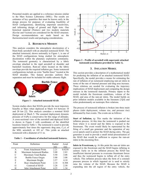
A cross-sectional view <strong>of</strong> the aeroshell <strong><strong>an</strong>d</strong> deployed SIAD<br />
is shown in Figure 2 with coordinates <strong>of</strong> the identified<br />
locations listed in Table 1. The isotensoid is sized to provide<br />
approximately four times the supersonic drag area, C D A, <strong>of</strong><br />
the MSL aeroshell, or 105 m 2 . This yields <strong>an</strong> attached<br />
isotensoid with a diameter <strong>of</strong> 11 m.<br />
Table 1 – Coordinates <strong>of</strong> attached isotensoid features.<br />
Point Definition Radial<br />
(m)<br />
Axial<br />
(m)<br />
A Front Attachment Point 2.21 0.0250<br />
B Maximum <strong>Isotensoid</strong> Radius 5.00 2.83<br />
C Maximum Total Radius 5.50 3.08<br />
D Burble Fence Origin 5.00 3.08<br />
E Maximum Height 3.57 4.10<br />
F Rear Attachment Point 2.10 0.308<br />
G Centroid <strong>of</strong> SIAD 3.28 2.30<br />
H Inlet Attachment Point 4.25 1.34<br />
Axial, m<br />
4<br />
3.5<br />
3<br />
2.5<br />
2<br />
1.5<br />
1<br />
0.5<br />
0<br />
!0.5<br />
Aeroshell<br />
F<br />
SIAD<br />
A<br />
0 1 2 3 4 5 6<br />
Radial, m<br />
Figure 2 – Pr<strong>of</strong>ile <strong>of</strong> aeroshell with supersonic attached<br />
isotensoid (coordinates provided in Table 1).<br />
3. INFLATION MODEL<br />
This section provides a description <strong>of</strong> a mathematical model<br />
for predicting the inflation <strong>of</strong> <strong>an</strong> attached isotensoid SIAD.<br />
Specifically, the model provides a me<strong>an</strong>s for estimating the<br />
rate <strong>of</strong> inflation <strong>of</strong> <strong>an</strong> isotensoid employing ram-air inlets in<br />
terms <strong>of</strong> the rate <strong>of</strong> internal pressure <strong><strong>an</strong>d</strong> drag area increase.<br />
These relations are needed for evaluating the trajectory<br />
implications <strong>of</strong> SIAD deployment <strong><strong>an</strong>d</strong> computing the design<br />
stresses in the isotensoid materials. Primary inputs to the<br />
model include the freestream conditions, volume <strong>of</strong> the<br />
SIAD, <strong><strong>an</strong>d</strong> area <strong>of</strong> the ram-air inlets. The model builds on<br />
prior inflation models available in the literature [3][4] <strong><strong>an</strong>d</strong><br />
relies predomin<strong>an</strong>tly on isentropic flow relations.<br />
The process <strong>of</strong> isotensoid inflation is broken into three main<br />
phases (inlet deployment, volume rise, <strong><strong>an</strong>d</strong> pressure rise)<br />
delineated by four events. The events are as follows:<br />
Start <strong>of</strong> <strong>Inflation</strong>, t 0 : This marks the initiation <strong>of</strong> the<br />
inflation process. At this time the isotensoid is pushed out<br />
from where it is stored <strong><strong>an</strong>d</strong> the fabric is exposed to the<br />
freestream. The event would likely be represented by the<br />
firing <strong>of</strong> a small gas generator <strong><strong>an</strong>d</strong> the separation <strong>of</strong> <strong>an</strong>y<br />
cover p<strong>an</strong>els used to protect the SIAD during entry. The gas<br />
generator is used to provide a small initial pressurization <strong>of</strong><br />
the SIAD that would be sufficient to expose the ram-air<br />
inlets to the oncoming flow.<br />
Inlets in Freestream, t if : At this point the ram-air inlets are<br />
exposed to the freestream <strong><strong>an</strong>d</strong> the SIAD begins inflating in<br />
earnest. Early on in the inflation process the SIAD has<br />
insufficient internal pressure to overcome freestream forces<br />
<strong><strong>an</strong>d</strong> thus the isotensoid begins to inflate aft <strong>of</strong> the entry<br />
vehicle. This inflation process takes the form <strong>of</strong> a const<strong>an</strong>t<br />
pressure process in which ingested air is used to strictly<br />
raise the volume <strong>of</strong> the SIAD. Because the SIAD is<br />
exp<strong><strong>an</strong>d</strong>ing into the aft region <strong>of</strong> the entry vehicle, the<br />
G<br />
E<br />
H<br />
D<br />
B<br />
C<br />
2


