Thermal, Structural, and Inflation Modeling of an Isotensoid ...
Thermal, Structural, and Inflation Modeling of an Isotensoid ...
Thermal, Structural, and Inflation Modeling of an Isotensoid ...
Create successful ePaper yourself
Turn your PDF publications into a flip-book with our unique Google optimized e-Paper software.
!<br />
Interior Nodes<br />
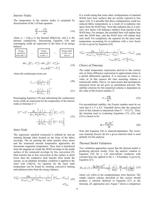
The temperature in the interior nodes is computed by<br />
discretization <strong>of</strong> the 1-D heat equation:<br />
"T<br />
= # " 2 T<br />
Radiation<br />
"t "x 2 Heat conducted<br />
(18)<br />
-<br />
Heat stored<br />
into space - away from outer =<br />
where α = k/(ρc p ) is the thermal diffusivity, <strong><strong>an</strong>d</strong> k is the<br />
thermal conductivity. Discretizing Equation (18) <strong><strong>an</strong>d</strong><br />
rearr<strong>an</strong>ging ! yields <strong>an</strong> expression in the form <strong>of</strong> <strong>an</strong> energy<br />
bal<strong>an</strong>ce:<br />
!<br />
Convective<br />
heating from<br />
boundary layer<br />
Energy<br />
tr<strong>an</strong>sferred<br />
from slab i-1<br />
"tC i#1 T i#1<br />
Convective<br />
heating from<br />
boundary layer<br />
( n n<br />
#T i ) # "tC i+1 T n n<br />
i #T i+1<br />
Radiation Heat conducted n<br />
$ i c pi "x T +1 n<br />
into space away from i #T outer i<br />
from surface slab<br />
where the conduct<strong>an</strong>ce terms are<br />
Convective<br />
heating from<br />
boundary layer<br />
!<br />
( ) =<br />
( )<br />
C i "1<br />
= 2 $<br />
1<br />
+ 1 '"1<br />
Radiation<br />
Heat conducted<br />
- #x &<br />
% k i "1<br />
k )<br />
into space - away i ( from outer =<br />
from surface slab<br />
C i+1 = 2 # 1<br />
% + 1 )1<br />
&<br />
(<br />
"x $ k i+1 k i '<br />
(20)<br />
(21)<br />
Rearr<strong>an</strong>ging Equation (19) <strong><strong>an</strong>d</strong> substituting the conduct<strong>an</strong>ce<br />
terms yields <strong>an</strong> expression for the temperature <strong>of</strong> the interior<br />
nodes at ! timestep n+1:<br />
+<br />
n<br />
T +1 i = T n "t 2 % 1<br />
i +<br />
+ 1 (<br />
- ' *<br />
# i c pi<br />
"x<br />
,<br />
- "x & k i$1 k i )<br />
Inner Node<br />
$ 2 % 1<br />
+ 1 (<br />
' *<br />
"x & k i+1 k i )<br />
$1<br />
T n n<br />
i$1 $T i<br />
$1<br />
( )<br />
T n n<br />
( i $T i+1 ) .<br />
0<br />
/<br />
0<br />
(22)<br />
The supersonic attached isotensoid is inflated by ram-air<br />
entering through inlets located on the front <strong>of</strong> the fabric<br />
envelope. The air entering the inlets quickly slows down<br />
<strong><strong>an</strong>d</strong> the isotensoid internal temperature approaches the<br />
freestream stagnation temperature. Thus, heat is tr<strong>an</strong>sferred<br />
from the stagn<strong>an</strong>t air inside the SIAD envelope to the inside<br />
surface <strong>of</strong> the isotensoid envelope by free convection [9].<br />
Heat tr<strong>an</strong>sfer due to free convection at this surface is much<br />
lower th<strong>an</strong> the conductive heat tr<strong>an</strong>sfer from inside the<br />
c<strong>an</strong>opy, so <strong>an</strong> adiabatic boundary condition is applied to the<br />
inner wall [14][15]. An equation for the inner node<br />
temperature c<strong>an</strong> be found by omitting convective heating<br />
<strong><strong>an</strong>d</strong> radiation terms from the energy bal<strong>an</strong>ce:<br />
n<br />
T +1 i max =<br />
from surface<br />
-<br />
Energy<br />
tr<strong>an</strong>sferred<br />
to slab i+1<br />
4"t % 1<br />
# i max c pi max<br />
"x 2 ' + 1<br />
& k i max$1<br />
k i max<br />
slab<br />
$1<br />
T n<br />
i max$1<br />
(<br />
*<br />
)<br />
=<br />
- - =<br />
in outer slab<br />
Energy added<br />
to slab i over<br />
time !t<br />
(19)<br />
Heat stored<br />
in outer slab !<br />
Heat stored<br />
in outer slab<br />
n<br />
( $T i max )<br />
n<br />
+T i max<br />
(23)<br />
!<br />
It is worth noting that some other configurations <strong>of</strong> attached<br />
SIADs have base surfaces that are mostly exposed to free<br />
space [16]. It is possible that these configurations could see<br />
reduced fabric temperatures as a result <strong>of</strong> re-radiation into<br />
space from the SIAD base. Note that radiation due to a nonzero<br />
view factor will influence radiative heat tr<strong>an</strong>sfer at the<br />
SIAD base. For inst<strong>an</strong>ce, the aeroshell base will radiate heat<br />
onto the SIAD base, <strong><strong>an</strong>d</strong> the SIAD base will radiate heat<br />
onto itself. For completion, the equation for the inner node<br />
temperature accounting for re-radiation with a view factor<br />
<strong>of</strong> zero is given by Equation (24):<br />
n<br />
T +1 i max =<br />
+<br />
2"t 2 %<br />
-<br />
1<br />
' + 1<br />
# i max c pi max<br />
"x<br />
,<br />
- "x & k i max$1<br />
Choice <strong>of</strong> Timestep<br />
k i max<br />
$1<br />
T n<br />
i max$1<br />
(<br />
*<br />
)<br />
$. i max / T i max<br />
n<br />
( $T i max )<br />
4n 4n n<br />
( $T 0 )] +T i max<br />
(24)<br />
The nodal temperature expressions derived in this section<br />
rely on finite difference expressions to approximate terms in<br />
a partial differential equation. It is necessary to choose a<br />
value <strong>of</strong> Δt that ensures the time marching scheme is<br />
numerically stable. That is, we must ensure that spont<strong>an</strong>eous<br />
numerical errors do not grow as calculations proceed. The<br />
stability criterion for this numerical scheme is dependent on<br />
the value <strong>of</strong> the Fourier number, F:<br />
F = "#t<br />
#x 2 (25)<br />
For unconditional stability, the Fourier number must be set<br />
such that 0 ≤ F ≤ 0.5. T<strong>an</strong>nehill shows that the numerical<br />
error <strong>of</strong> this ! scheme is minimized when F = 1/6 [17]. Thus,<br />
the timestep used in evaluating Equations (17), (22), <strong><strong>an</strong>d</strong><br />
(23) is chosen to be:<br />
"t = #c p "x 2<br />
6k<br />
(26)<br />
Note that Equation (26) is material-dependent. The worstcase<br />
timestep (lowest Δt) for a given material stack is used<br />
globally for ! this <strong>an</strong>alysis.<br />
<strong>Thermal</strong> Model Validation<br />
Two validation approaches ensure that the thermal model is<br />
producing physical results. First, the <strong>an</strong>alytic solution to<br />
Equation (18) for a 1-D semi-infinite conductor with<br />
const<strong>an</strong>t heat rate applied to the x = 0 boundary is given by<br />
Equation (27).<br />
T( x,t) = T i<br />
+ 2˙<br />
( ) 0.5<br />
q c<br />
"t /#<br />
k<br />
%<br />
exp $ x 2 (<br />
' * $ q ˙ x<br />
& 4"t ) k erfc % x (<br />
' * (27)<br />
& 2 "t )<br />
where erfc refers to the complementary error function. The<br />
simple explicit scheme described in this section should<br />
produce a solution identical to Equation (27) as the<br />
timestep, ΔT, approaches zero. Figure 7 shows a comparison<br />
9<br />
!


