Thermal, Structural, and Inflation Modeling of an Isotensoid ...
Thermal, Structural, and Inflation Modeling of an Isotensoid ...
Thermal, Structural, and Inflation Modeling of an Isotensoid ...
Create successful ePaper yourself
Turn your PDF publications into a flip-book with our unique Google optimized e-Paper software.
!<br />
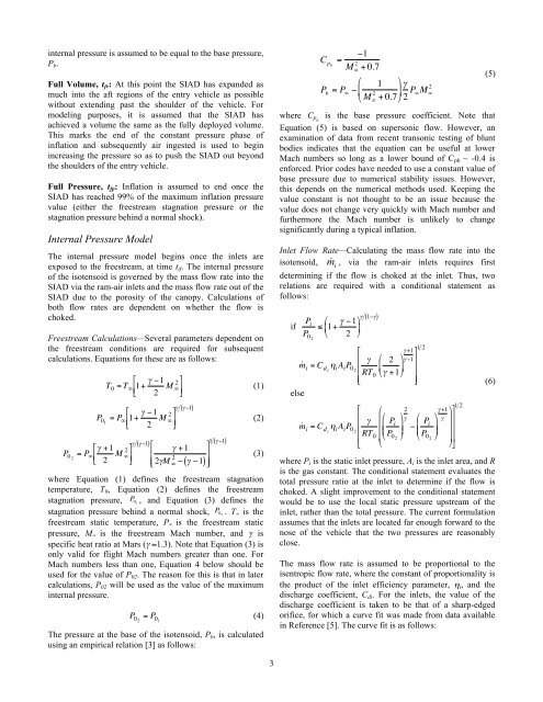
internal pressure is assumed to be equal to the base pressure,<br />
P b .<br />
Full Volume, t fv : At this point the SIAD has exp<strong><strong>an</strong>d</strong>ed as<br />
much into the aft regions <strong>of</strong> the entry vehicle as possible<br />
without extending past the shoulder <strong>of</strong> the vehicle. For<br />
modeling purposes, it is assumed that the SIAD has<br />
achieved a volume the same as the fully deployed volume.<br />
This marks the end <strong>of</strong> the const<strong>an</strong>t pressure phase <strong>of</strong><br />
inflation <strong><strong>an</strong>d</strong> subsequently air ingested is used to begin<br />
increasing the pressure so as to push the SIAD out beyond<br />
the shoulders <strong>of</strong> the entry vehicle.<br />
Full Pressure, t fp : <strong>Inflation</strong> is assumed to end once the<br />
SIAD has reached 99% <strong>of</strong> the maximum inflation pressure<br />
value (either the freestream stagnation pressure or the<br />
stagnation pressure behind a normal shock).<br />
Internal Pressure Model<br />
The internal pressure model begins once the inlets are<br />
exposed to the freestream, at time t if . The internal pressure<br />
<strong>of</strong> the isotensoid is governed by the mass flow rate into the<br />
SIAD via the ram-air inlets <strong><strong>an</strong>d</strong> the mass flow rate out <strong>of</strong> the<br />
SIAD due to the porosity <strong>of</strong> the c<strong>an</strong>opy. Calculations <strong>of</strong><br />
both flow rates are dependent on whether the flow is<br />
choked.<br />
Freestream Calculations—Several parameters dependent on<br />
the freestream conditions are required for subsequent<br />
calculations. Equations for these are as follows:<br />
!<br />
$ # +1<br />
P 02<br />
= P "<br />
! 2 M 2 '<br />
"<br />
%<br />
&<br />
(<br />
)<br />
%<br />
T 0 = T " 1+ # $1<br />
2 M 2 (<br />
"<br />
&<br />
'<br />
)<br />
* (1)<br />
%<br />
P 01<br />
= P " 1+ # $1<br />
2 M " 2 (<br />
&<br />
'<br />
)<br />
*<br />
# (# *1)<br />
# (# $1)<br />
1<br />
$<br />
# +1<br />
'<br />
(# *1)<br />
&<br />
)<br />
%&<br />
2#M 2 " * (# *1)<br />
()<br />
where Equation (1) defines the freestream stagnation<br />
!<br />
temperature, T 0 , Equation (2) defines the freestream<br />
stagnation pressure, P 01 , <strong><strong>an</strong>d</strong> Equation (3) defines the<br />
stagnation pressure behind a normal shock, P 02 . T ∞ is the<br />
freestream static temperature, P ∞ is the freestream static<br />
pressure, M ∞ is the freestream Mach number, <strong><strong>an</strong>d</strong> γ is<br />
specific heat ratio at Mars (γ ≈1.3). Note that Equation (3) is<br />
only valid for flight Mach numbers greater th<strong>an</strong> one. For<br />
Mach numbers less th<strong>an</strong> one, Equation 4 below should be<br />
used for the value <strong>of</strong> P 02 . The reason for this is that in later<br />
calculations, P 02 will be used as the value <strong>of</strong> the maximum<br />
internal pressure.<br />
The pressure at the base <strong>of</strong> the isotensoid, P b , is calculated<br />
using <strong>an</strong> empirical relation [3] as follows:<br />
!<br />
(2)<br />
(3)<br />
P 02<br />
= P 01<br />
(4)<br />
3<br />
C pb<br />
=<br />
"1<br />
M # 2 + 0.7<br />
$ 1 '<br />
P b<br />
= P #<br />
"&<br />
) * % M 2 #<br />
+ 0.7(<br />
2 P 2<br />
#M #<br />
where C pb is the base pressure coefficient. Note that<br />
Equation (5) is based on supersonic flow. However, <strong>an</strong><br />
examination ! <strong>of</strong> data from recent tr<strong>an</strong>sonic testing <strong>of</strong> blunt<br />
bodies indicates that the equation c<strong>an</strong> be useful at lower<br />
Mach numbers so long as a lower bound <strong>of</strong> C pb ~ -0.4 is<br />
enforced. Prior codes have needed to use a const<strong>an</strong>t value <strong>of</strong><br />
base pressure due to numerical stability issues. However,<br />
this depends on the numerical methods used. Keeping the<br />
value const<strong>an</strong>t is not thought to be <strong>an</strong> issue because the<br />
value does not ch<strong>an</strong>ge very quickly with Mach number <strong><strong>an</strong>d</strong><br />
furthermore the Mach number is unlikely to ch<strong>an</strong>ge<br />
signific<strong>an</strong>tly during a typical inflation.<br />
Inlet Flow Rate—Calculating the mass flow rate into the<br />
isotensoid, !m i<br />
, via the ram-air inlets requires first<br />
determining if the flow is choked at the inlet. Thus, two<br />
relations are required with a conditional statement as<br />
follows:<br />
if<br />
( )<br />
P i<br />
%<br />
" 1+ # $1 (<br />
# 1$#<br />
' *<br />
P 02<br />
& 2 )<br />
,<br />
. # % 2 (<br />
m ˙ i = C d i<br />
+ i A i P 02 . ' *<br />
RT 0 &# +1)<br />
-.<br />
else<br />
, %<br />
. # '%<br />
m ˙ i = C d i<br />
+ i A i P 02 . '<br />
RT '<br />
. 0 '&<br />
- &<br />
P i<br />
P 02<br />
# +1<br />
1 2<br />
/<br />
# $1<br />
2<br />
1<br />
1<br />
01<br />
(# %<br />
P<br />
(<br />
* $ i<br />
'<br />
) & P *<br />
02 )<br />
# +1<br />
#<br />
where P i is the static inlet pressure, A i is the inlet area, <strong><strong>an</strong>d</strong> R<br />
is the gas const<strong>an</strong>t. The conditional statement evaluates the<br />
total pressure ratio at the inlet to determine if the flow is<br />
choked. A slight improvement to the conditional statement<br />
would be to use the local static pressure upstream <strong>of</strong> the<br />
inlet, rather th<strong>an</strong> the total pressure. The current formulation<br />
assumes that the inlets are located far enough forward to the<br />
nose <strong>of</strong> the vehicle that the two pressures are reasonably<br />
close.<br />
The mass flow rate is assumed to be proportional to the<br />
isentropic flow rate, where the const<strong>an</strong>t <strong>of</strong> proportionality is<br />
the product <strong>of</strong> the inlet efficiency parameter, η i , <strong><strong>an</strong>d</strong> the<br />
discharge coefficient, C di . For the inlets, the value <strong>of</strong> the<br />
discharge coefficient is taken to be that <strong>of</strong> a sharp-edged<br />
orifice, for which a curve fit was made from data available<br />
in Reference [5]. The curve fit is as follows:<br />
(/<br />
* 1<br />
* 1<br />
* 1<br />
) 0<br />
1 2<br />
(5)<br />
(6)


