Operation and assembly instruction (USA): 261430 ... - Dungs Mobile
Operation and assembly instruction (USA): 261430 ... - Dungs Mobile
Operation and assembly instruction (USA): 261430 ... - Dungs Mobile

Create successful ePaper yourself
Turn your PDF publications into a flip-book with our unique Google optimized e-Paper software.
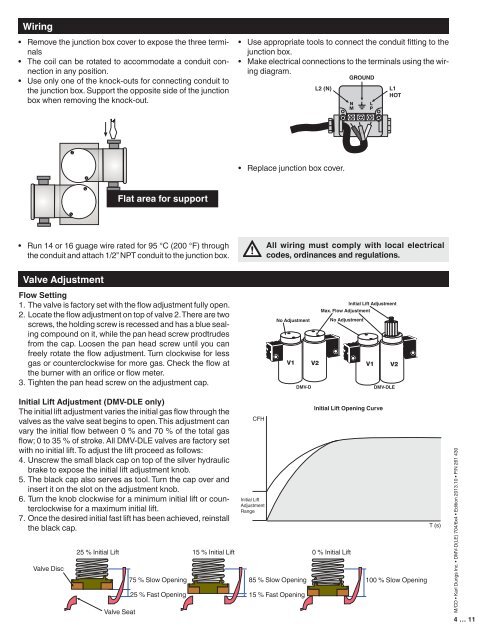
Wiring<br />
• Remove the junction box cover to expose the three terminals<br />
• The coil can be rotated to accommodate a conduit connection<br />
in any position.<br />
• Use only one of the knock-outs for connecting conduit to<br />
the junction box. Support the opposite side of the junction<br />
box when removing the knock-out.<br />
• Use appropriate tools to connect the conduit fitting to the<br />
junction box.<br />
• Make electrical connections to the terminals using the wiring<br />
diagram.<br />
L2 (N)<br />
GROUND<br />
L1<br />
HOT<br />
• Replace junction box cover.<br />
Flat area for support<br />
• Run 14 or 16 guage wire rated for 95 °C (200 °F) through<br />
the conduit <strong>and</strong> attach 1/2” NPT conduit to the junction box.<br />
All wiring must comply with local electrical<br />
codes, ordinances <strong>and</strong> regulations.<br />
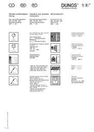
Valve Adjustment<br />
Flow Setting<br />
1. The valve is factory set with the flow adjustment fully open.<br />
2. Locate the flow adjustment on top of valve 2. There are two<br />
screws, the holding screw is recessed <strong>and</strong> has a blue sealing<br />
compound on it, while the pan head screw prodtrudes<br />
from the cap. Loosen the pan head screw until you can<br />
freely rotate the flow adjustment. Turn clockwise for less<br />
gas or counterclockwise for more gas. Check the flow at<br />
the burner with an orifice or flow meter.<br />
3. Tighten the pan head screw on the adjustment cap.<br />
No Adjustment<br />
DMV-D<br />
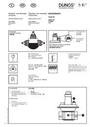
Initial Lift Adjustment<br />
Max. Flow Adjustment<br />
No Adjustment<br />
DMV-DLE<br />
Initial Lift Adjustment (DMV-DLE only)<br />
The initial lift adjustment varies the initial gas flow through the<br />
valves as the valve seat begins to open. This adjustment can<br />
vary the initial flow between 0 % <strong>and</strong> 70 % of the total gas<br />
flow; 0 to 35 % of stroke. All DMV-DLE valves are factory set<br />
with no initial lift. To adjust the lift proceed as follows:<br />
4. Unscrew the small black cap on top of the silver hydraulic<br />
brake to expose the initial lift adjustment knob.<br />
5. The black cap also serves as tool. Turn the cap over <strong>and</strong><br />
insert it on the slot on the adjustment knob.<br />
6. Turn the knob clockwise for a minimum initial lift or counterclockwise<br />
for a maximum initial lift.<br />
7. Once the desired initial fast lift has been achieved, reinstall<br />
the black cap.<br />
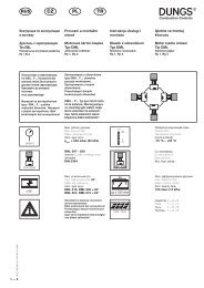
Valve Disc<br />
25 % Initial Lift 15 % Initial Lift 0 % Initial Lift<br />
Valve Seat<br />
75 % Slow Opening<br />
CFH<br />
Initial Lift<br />
Adjustment<br />
Range<br />
25 % Fast Opening 15 % Fast Opening<br />
Initial Lift Opening Curve<br />
85 % Slow Opening 100 % Slow Opening<br />
T (s)<br />
M/CD • Karl <strong>Dungs</strong> Inc. • DMV-D(LE) 704/6x4 • Edition 2013.10 • P/N 261 430<br />
4 … 11