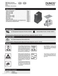
Operation and assembly instruction (USA): 261430 ... - Dungs Mobile
Operation and assembly instruction (USA): 261430 ... - Dungs Mobile
Operation and assembly instruction (USA): 261430 ... - Dungs Mobile

You also want an ePaper? Increase the reach of your titles
YUMPU automatically turns print PDFs into web optimized ePapers that Google loves.
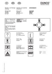
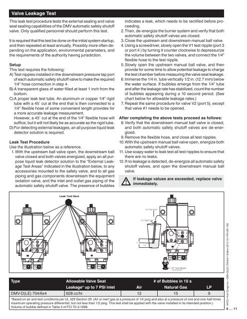
Valve Leakage Test<br />
This leak test procedure tests the external sealing <strong>and</strong> valve<br />
seat sealing capabilities of the DMV automatic safety shutoff<br />
valve. Only qualified personnel should perform this test.<br />
It is required that this test be done on the initial system startup,<br />
<strong>and</strong> then repeated at least annually. Possibly more often depending<br />
on the application, environmental parameters, <strong>and</strong><br />
the requirements of the authority having jurisdiction.<br />
Setup<br />
This test requires the following:<br />
A) Test nipples installed in the downstream pressure tap port<br />
of each automatic safety shutoff valve to make the required<br />
1/4” hose connection in step 4.<br />
B) A transparent glass of water filled at least 1 inch from the<br />
bottom.<br />
C) A proper leak test tube. An aluminum or copper 1/4” rigid<br />
tube with a 45˚ cut at the end that is then connected to a<br />
1/4” flexible hose of some convenient length provides for<br />
a more accurate leakage measurement.<br />
However, a 45˚ cut at the end of the 1/4” flexible hose will<br />
suffice, but it will not likely be as accurate as the rigid tube.<br />
D) For detecting external leakages, an all purpose liquid leak<br />
detector solution is required.<br />
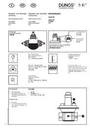
Leak Test Procedure<br />
Use the illustration below as a reference.<br />
1. With the upstream ball valve open, the downstream ball<br />
valve closed <strong>and</strong> both valves energized, apply an all purpose<br />
liquid leak detector solution to the “External Leakage<br />
Test Areas” indicated in the illustration below, to any<br />
accessories mounted to the safety valve, <strong>and</strong> to all gas<br />
piping <strong>and</strong> gas components downstream the equipment<br />
isolation valve, <strong>and</strong> the inlet <strong>and</strong> outlet gas piping of the<br />
automatic safety shutoff valve. The presence of bubbles<br />
indicates a leak, which needs to be rectified before proceeding.<br />
2. Then, de-energize the burner system <strong>and</strong> verify that both<br />
automatic safety shutoff valves are closed.<br />
3. Close the upstream <strong>and</strong> downstream manual ball valve.<br />
4. Using a screwdriver, slowly open the V1 test nipple (port 3<br />
or port 4 ) by turning it counter clockwise to depressurize<br />
the volume between the two valves, <strong>and</strong> connect the 1/4”<br />
flexible hose to the test nipple.<br />
5. Slowly open the upstream manual ball valve, <strong>and</strong> then<br />
provide for some time to allow potential leakage to charge<br />
the test chamber before measuring the valve seat leakage.<br />
6. Immerse the 1/4 in. tube vertically 1/2 in. (12.7 mm) below<br />
the water surface. If bubbles emerge from the 1/4” tube<br />
<strong>and</strong> after the leakage rate has stabilized, count the number<br />
of bubbles appearing during a 10 second period. (See<br />
chart below for allowable leakage rates.)<br />
7. Repeat the same procedure for valve V2 (port 5), except<br />
that valve #1 needs to be opened.<br />
After completing the above tests proceed as follows:<br />
8. Verify that the downstream manual ball valve is closed,<br />
<strong>and</strong> both automatic safety shutoff valves are de-energized.<br />
9. Remove the flexible hose, <strong>and</strong> close all test nipples.<br />
10. With the upstream manual ball valve open, energize both<br />
automatic safety shutoff valves.<br />
11. Use soapy water to leak test all test nipples to ensure that<br />
there are no leaks.<br />
12. If no leakage is detected, de-energize all automatic safety<br />
shutoff valves, <strong>and</strong> open the downstream manual ball<br />
valve.<br />
If leakage values are exceeded, replace valve<br />
immediately.<br />
Type Allowable Valve Seat # of Bubbles in 10 s<br />
Leakage* up to 7 PSI inlet Air Natural Gas LP<br />
DMV-D(LE) 704/6x4 628 cc/hr 12 15 9<br />
*Based on air <strong>and</strong> test conditions per UL 429 Section 29. (Air or inert gas at a pressure of 1/4 psig <strong>and</strong> also at a pressure of one <strong>and</strong> one-half times<br />
maximum operating pressure differential, but not less than 1/2 psig. This test shall be applied with the valve installed in its intended position.)<br />
Volume of bubble defined in Table 2 of FCI 70-2-1998.<br />
M/CD • Karl <strong>Dungs</strong> Inc. • DMV-D(LE) 704/6x4 • Edition 2013.10 • P/N 261 430<br />
6 … 11