ug900-vivado-logic-simulation
ug900-vivado-logic-simulation
ug900-vivado-logic-simulation

You also want an ePaper? Increase the reach of your titles
YUMPU automatically turns print PDFs into web optimized ePapers that Google loves.
Vivado Design Suite<br />
User Guide<br />
Logic Simulation<br />
UG900 (v2014.1) April 23, 2014
Revision History<br />
The following table shows the revision history for this document.<br />
Date Version Revision<br />
04/23/2014 2014.1 Coded example for running a post-synthesis functional <strong>simulation</strong> from the command<br />
line corrected, page 112.<br />
Corrected information about switches in the section Compiling Simulation Libraries<br />
for VCS, page 149.<br />
Updated usage information on VCS Script Simulation, page 152.<br />
Added Appendix D, SystemVerilog Constructs Supported by the Vivado Simulator<br />
(early access).<br />
IDS_lite is obsolete; references to it have been removed.<br />
General updates made to reflect changes in version 2014.1, including SystemVerilog<br />
information, updates to graphics.<br />
Revisions and enhancements throughout, including updates to cross references and<br />
citations; addition of instructions on locating and displaying GUI features.<br />
Logic Simulation www.xilinx.com<br />
Send Feedback<br />
2<br />
UG900 (v2014.1) April 23, 2014
Table of Contents<br />
Chapter 1: Logic Simulation Overview<br />
Introduction . . . . . . . . . . . . . . . . . . . . . . . . . . . . . . . . . . . . . . . . . . . . . . . . . . . . . . . . . . . . . . . . . . . . . . 6<br />
Simulation Flow . . . . . . . . . . . . . . . . . . . . . . . . . . . . . . . . . . . . . . . . . . . . . . . . . . . . . . . . . . . . . . . . . . . 6<br />
Supported Simulators . . . . . . . . . . . . . . . . . . . . . . . . . . . . . . . . . . . . . . . . . . . . . . . . . . . . . . . . . . . . . . 9<br />
Language and Encryption Support . . . . . . . . . . . . . . . . . . . . . . . . . . . . . . . . . . . . . . . . . . . . . . . . . . . 10<br />
OS Support and Release Changes . . . . . . . . . . . . . . . . . . . . . . . . . . . . . . . . . . . . . . . . . . . . . . . . . . . . 10<br />
Chapter 2: Understanding Simulation Components in Vivado<br />
Introduction . . . . . . . . . . . . . . . . . . . . . . . . . . . . . . . . . . . . . . . . . . . . . . . . . . . . . . . . . . . . . . . . . . . . . 11<br />
Using Test Benches and Stimulus Files . . . . . . . . . . . . . . . . . . . . . . . . . . . . . . . . . . . . . . . . . . . . . . . . 12<br />
Using Xilinx Simulation Libraries. . . . . . . . . . . . . . . . . . . . . . . . . . . . . . . . . . . . . . . . . . . . . . . . . . . . . 13<br />
Compiling Simulation Libraries . . . . . . . . . . . . . . . . . . . . . . . . . . . . . . . . . . . . . . . . . . . . . . . . . . . . . . 24<br />
Understanding the Simulator Language Option . . . . . . . . . . . . . . . . . . . . . . . . . . . . . . . . . . . . . . . . 25<br />
Using the export_<strong>simulation</strong> Command. . . . . . . . . . . . . . . . . . . . . . . . . . . . . . . . . . . . . . . . . . . . . . . 27<br />
Recommended Simulation Resolution . . . . . . . . . . . . . . . . . . . . . . . . . . . . . . . . . . . . . . . . . . . . . . . . 29<br />
Generating a Netlist. . . . . . . . . . . . . . . . . . . . . . . . . . . . . . . . . . . . . . . . . . . . . . . . . . . . . . . . . . . . . . . 29<br />
Annotating the SDF File . . . . . . . . . . . . . . . . . . . . . . . . . . . . . . . . . . . . . . . . . . . . . . . . . . . . . . . . . . . . 30<br />
Using Global Reset and 3-State. . . . . . . . . . . . . . . . . . . . . . . . . . . . . . . . . . . . . . . . . . . . . . . . . . . . . . 31<br />
Delta Cycles and Race Conditions . . . . . . . . . . . . . . . . . . . . . . . . . . . . . . . . . . . . . . . . . . . . . . . . . . . . 33<br />
Using the ASYNC_REG Constraint . . . . . . . . . . . . . . . . . . . . . . . . . . . . . . . . . . . . . . . . . . . . . . . . . . . . 34<br />
Simulating Configuration Interfaces . . . . . . . . . . . . . . . . . . . . . . . . . . . . . . . . . . . . . . . . . . . . . . . . . . 35<br />
Disabling Block RAM Collision Checks for Simulation . . . . . . . . . . . . . . . . . . . . . . . . . . . . . . . . . . . . 39<br />
Dumping the Switching Activity Interchange Format File for Power Analysis . . . . . . . . . . . . . . . . 40<br />
Chapter 3: Using the Vivado Simulator from the Vivado IDE<br />
Introduction . . . . . . . . . . . . . . . . . . . . . . . . . . . . . . . . . . . . . . . . . . . . . . . . . . . . . . . . . . . . . . . . . . . . . 41<br />
Vivado Simulator Features . . . . . . . . . . . . . . . . . . . . . . . . . . . . . . . . . . . . . . . . . . . . . . . . . . . . . . . . . 41<br />
Adding or Creating Simulation Source Files . . . . . . . . . . . . . . . . . . . . . . . . . . . . . . . . . . . . . . . . . . . . 42<br />
Running the Vivado Simulator . . . . . . . . . . . . . . . . . . . . . . . . . . . . . . . . . . . . . . . . . . . . . . . . . . . . . . 51<br />
Running Post-Synthesis Simulation . . . . . . . . . . . . . . . . . . . . . . . . . . . . . . . . . . . . . . . . . . . . . . . . . . 59<br />
Running Post-Implementation Simulations . . . . . . . . . . . . . . . . . . . . . . . . . . . . . . . . . . . . . . . . . . . . 61<br />
Identifying Between Multiple Simulation Runs . . . . . . . . . . . . . . . . . . . . . . . . . . . . . . . . . . . . . . . . . 62<br />
Pausing a Simulation . . . . . . . . . . . . . . . . . . . . . . . . . . . . . . . . . . . . . . . . . . . . . . . . . . . . . . . . . . . . . . 62<br />
Logic Simulation www.xilinx.com Send Feedback 3<br />
UG900 (v2014.1) April 23, 2014
Saving Simulation Results . . . . . . . . . . . . . . . . . . . . . . . . . . . . . . . . . . . . . . . . . . . . . . . . . . . . . . . . . . 63<br />
Closing Simulation . . . . . . . . . . . . . . . . . . . . . . . . . . . . . . . . . . . . . . . . . . . . . . . . . . . . . . . . . . . . . . . . 63<br />
Adding a post.tcl Batch File . . . . . . . . . . . . . . . . . . . . . . . . . . . . . . . . . . . . . . . . . . . . . . . . . . . . . . . . . 63<br />
Skipping Compilation or Simulation . . . . . . . . . . . . . . . . . . . . . . . . . . . . . . . . . . . . . . . . . . . . . . . . . . 64<br />
Viewing Simulation Messages. . . . . . . . . . . . . . . . . . . . . . . . . . . . . . . . . . . . . . . . . . . . . . . . . . . . . . . 64<br />
Chapter 4: Analyzing with the Vivado Simulator Waveforms<br />
Introduction . . . . . . . . . . . . . . . . . . . . . . . . . . . . . . . . . . . . . . . . . . . . . . . . . . . . . . . . . . . . . . . . . . . . . 66<br />
Using Wave Configurations and Windows . . . . . . . . . . . . . . . . . . . . . . . . . . . . . . . . . . . . . . . . . . . . . 66<br />
Opening a Previously Saved Simulation Run . . . . . . . . . . . . . . . . . . . . . . . . . . . . . . . . . . . . . . . . . . . 68<br />
Understanding HDL Objects in Waveform Configurations . . . . . . . . . . . . . . . . . . . . . . . . . . . . . . . . 69<br />
Customizing the Waveform. . . . . . . . . . . . . . . . . . . . . . . . . . . . . . . . . . . . . . . . . . . . . . . . . . . . . . . . . 74<br />
Controlling the Waveform Display . . . . . . . . . . . . . . . . . . . . . . . . . . . . . . . . . . . . . . . . . . . . . . . . . . . 82<br />
Organizing Waveforms . . . . . . . . . . . . . . . . . . . . . . . . . . . . . . . . . . . . . . . . . . . . . . . . . . . . . . . . . . . . 84<br />
Analyzing Waveforms . . . . . . . . . . . . . . . . . . . . . . . . . . . . . . . . . . . . . . . . . . . . . . . . . . . . . . . . . . . . . 86<br />
Using Force Options. . . . . . . . . . . . . . . . . . . . . . . . . . . . . . . . . . . . . . . . . . . . . . . . . . . . . . . . . . . . . . . 89<br />
Chapter 5: Using Vivado Simulator Command Line and Tcl<br />
Introduction . . . . . . . . . . . . . . . . . . . . . . . . . . . . . . . . . . . . . . . . . . . . . . . . . . . . . . . . . . . . . . . . . . . . . 93<br />
Compiling and Simulating a Design . . . . . . . . . . . . . . . . . . . . . . . . . . . . . . . . . . . . . . . . . . . . . . . . . . 93<br />
Elaborating and Generating a Design Snapshot. . . . . . . . . . . . . . . . . . . . . . . . . . . . . . . . . . . . . . . . . 95<br />
Simulating the Design Snapshot . . . . . . . . . . . . . . . . . . . . . . . . . . . . . . . . . . . . . . . . . . . . . . . . . . . . 100<br />
Example of Running Vivado Simulator in Standalone Mode . . . . . . . . . . . . . . . . . . . . . . . . . . . . . 107<br />
Project File (.prj) Syntax . . . . . . . . . . . . . . . . . . . . . . . . . . . . . . . . . . . . . . . . . . . . . . . . . . . . . . . . . . 108<br />
Predefined Macros. . . . . . . . . . . . . . . . . . . . . . . . . . . . . . . . . . . . . . . . . . . . . . . . . . . . . . . . . . . . . . . 109<br />
Library Mapping File (xsim.ini) . . . . . . . . . . . . . . . . . . . . . . . . . . . . . . . . . . . . . . . . . . . . . . . . . . . . . 109<br />
Running Simulation Modes . . . . . . . . . . . . . . . . . . . . . . . . . . . . . . . . . . . . . . . . . . . . . . . . . . . . . . . . 111<br />
Using Tcl Commands and Scripts . . . . . . . . . . . . . . . . . . . . . . . . . . . . . . . . . . . . . . . . . . . . . . . . . . . 113<br />
Tcl Property Commands . . . . . . . . . . . . . . . . . . . . . . . . . . . . . . . . . . . . . . . . . . . . . . . . . . . . . . . . . . 114<br />
Chapter 6: Debugging a Design with Vivado Simulator<br />
Introduction . . . . . . . . . . . . . . . . . . . . . . . . . . . . . . . . . . . . . . . . . . . . . . . . . . . . . . . . . . . . . . . . . . . . 118<br />
Debugging at the Source Level . . . . . . . . . . . . . . . . . . . . . . . . . . . . . . . . . . . . . . . . . . . . . . . . . . . . . 118<br />
Generating (forcing) Stimulus . . . . . . . . . . . . . . . . . . . . . . . . . . . . . . . . . . . . . . . . . . . . . . . . . . . . . . 121<br />
Power Analysis Using Vivado Simulator. . . . . . . . . . . . . . . . . . . . . . . . . . . . . . . . . . . . . . . . . . . . . . 126<br />
Using the report_drivers Tcl Command . . . . . . . . . . . . . . . . . . . . . . . . . . . . . . . . . . . . . . . . . . . . . . 127<br />
Using the Value Change Dump Feature . . . . . . . . . . . . . . . . . . . . . . . . . . . . . . . . . . . . . . . . . . . . . . 128<br />
Chapter 7: Simulating with QuestaSim/ModelSim<br />
Introduction . . . . . . . . . . . . . . . . . . . . . . . . . . . . . . . . . . . . . . . . . . . . . . . . . . . . . . . . . . . . . . . . . . . . 129<br />
Logic Simulation www.xilinx.com Send Feedback 4<br />
UG900 (v2014.1) April 23, 2014
Simulating Xilinx Designs using QuestaSim/ModelSim. . . . . . . . . . . . . . . . . . . . . . . . . . . . . . . . . . 129<br />
Chapter 8: Simulating with Cadence Incisive Enterprise Simulator (IES)<br />
Introduction . . . . . . . . . . . . . . . . . . . . . . . . . . . . . . . . . . . . . . . . . . . . . . . . . . . . . . . . . . . . . . . . . . . . 142<br />
Compiling Simulation Libraries for IES . . . . . . . . . . . . . . . . . . . . . . . . . . . . . . . . . . . . . . . . . . . . . . . 142<br />
Running Behavioral/RTL Simulation Using IES. . . . . . . . . . . . . . . . . . . . . . . . . . . . . . . . . . . . . . . . . 143<br />
IES Simulation Use models . . . . . . . . . . . . . . . . . . . . . . . . . . . . . . . . . . . . . . . . . . . . . . . . . . . . . . . . 145<br />
Running Timing Simulation Using IES . . . . . . . . . . . . . . . . . . . . . . . . . . . . . . . . . . . . . . . . . . . . . . . . 147<br />
Dumping SAIF for Power Analysis in IES. . . . . . . . . . . . . . . . . . . . . . . . . . . . . . . . . . . . . . . . . . . . . . 148<br />
Chapter 9: Simulating with Synopsys VCS<br />
Introduction . . . . . . . . . . . . . . . . . . . . . . . . . . . . . . . . . . . . . . . . . . . . . . . . . . . . . . . . . . . . . . . . . . . . 149<br />
Running Behavioral/RTL Simulation using VCS . . . . . . . . . . . . . . . . . . . . . . . . . . . . . . . . . . . . . . . . 150<br />
VCS Simulation Use Models . . . . . . . . . . . . . . . . . . . . . . . . . . . . . . . . . . . . . . . . . . . . . . . . . . . . . . . 153<br />
Appendix A: Value Rules in Vivado Simulator Tcl Commands<br />
Introduction . . . . . . . . . . . . . . . . . . . . . . . . . . . . . . . . . . . . . . . . . . . . . . . . . . . . . . . . . . . . . . . . . . . . 156<br />
String Value Interpretation . . . . . . . . . . . . . . . . . . . . . . . . . . . . . . . . . . . . . . . . . . . . . . . . . . . . . . . . 156<br />
Vivado Simulation Logic . . . . . . . . . . . . . . . . . . . . . . . . . . . . . . . . . . . . . . . . . . . . . . . . . . . . . . . . . . 157<br />
Appendix B: Vivado Simulator Mixed Language Support and Language<br />
Exceptions<br />
Introduction . . . . . . . . . . . . . . . . . . . . . . . . . . . . . . . . . . . . . . . . . . . . . . . . . . . . . . . . . . . . . . . . . . . . 158<br />
Using Mixed Language Simulation . . . . . . . . . . . . . . . . . . . . . . . . . . . . . . . . . . . . . . . . . . . . . . . . . . 158<br />
VHDL Language Support Exceptions . . . . . . . . . . . . . . . . . . . . . . . . . . . . . . . . . . . . . . . . . . . . . . . . . 163<br />
Verilog Language Support Exceptions . . . . . . . . . . . . . . . . . . . . . . . . . . . . . . . . . . . . . . . . . . . . . . . 165<br />
Appendix C: Vivado Simulator Quick Reference Guide<br />
Appendix D: SystemVerilog Constructs Supported by the Vivado Simulator<br />
Introduction . . . . . . . . . . . . . . . . . . . . . . . . . . . . . . . . . . . . . . . . . . . . . . . . . . . . . . . . . . . . . . . . . . . . 172<br />
Appendix E: Additional Resources and Legal Notices<br />
Xilinx Resources . . . . . . . . . . . . . . . . . . . . . . . . . . . . . . . . . . . . . . . . . . . . . . . . . . . . . . . . . . . . . . . . . 179<br />
Solution Centers. . . . . . . . . . . . . . . . . . . . . . . . . . . . . . . . . . . . . . . . . . . . . . . . . . . . . . . . . . . . . . . . . 179<br />
Documentation References. . . . . . . . . . . . . . . . . . . . . . . . . . . . . . . . . . . . . . . . . . . . . . . . . . . . . . . . 179<br />
Quick Take Videos . . . . . . . . . . . . . . . . . . . . . . . . . . . . . . . . . . . . . . . . . . . . . . . . . . . . . . . . . . . . . . . 180<br />
Links to Language and Encryption Support Standards . . . . . . . . . . . . . . . . . . . . . . . . . . . . . . . . . . 180<br />
Please Read: Important Legal Notices . . . . . . . . . . . . . . . . . . . . . . . . . . . . . . . . . . . . . . . . . . . . . . . 180<br />
Logic Simulation www.xilinx.com Send Feedback 5<br />
UG900 (v2014.1) April 23, 2014
Chapter 1<br />
Logic Simulation Overview<br />
Introduction<br />
Simulation is a process of emulating the real design behavior in a software environment.<br />
Simulation helps verify the functionality of a design by injecting stimulus and observing the<br />
design outputs.<br />
This chapter provides an overview of the <strong>simulation</strong> process, and the <strong>simulation</strong> options in<br />
the Vivado ® Design Suite. The Vivado Design Suite Integrated Design Environment (IDE)<br />
provides an integrated <strong>simulation</strong> environment when using the Vivado simulator.<br />
For more information about the Vivado IDE and the Vivado Design Suite flow, see:<br />
• Vivado Design Suite User Guide: Using the Vivado IDE (UG893) [Ref 2]<br />
• Vivado Design Suite User Guide: Design Flows Overview (UG892) [Ref 9]<br />
Simulation Flow<br />
Simulation can be applied at several points in the design flow. It is one of the first steps<br />
after design entry and one of the last steps after implementation as part of the verifying the<br />
end functionality and performance of the design.<br />
Simulation is an iterative process and is typically repeated until both the design<br />
functionality and timing requirements are satisfied.<br />
Logic Simulation www.xilinx.com<br />
Send Feedback<br />
6<br />
UG900 (v2014.1) April 23, 2014
Chapter 1: Logic Simulation Overview<br />
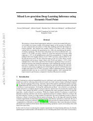
The following figure illustrates the <strong>simulation</strong> flow for a typical design:<br />
X-Ref Target - Figure 1-1<br />
<br />
<br />
<br />
<br />
<br />
<br />
<br />
<br />
<br />
Figure 1-1:<br />
Simulation Flow<br />
Logic Simulation www.xilinx.com<br />
Send Feedback<br />
7<br />
UG900 (v2014.1) April 23, 2014
Chapter 1: Logic Simulation Overview<br />
Behavioral Simulation at the Register Transfer Level<br />
Register Transfer Level (RTL), behavioral <strong>simulation</strong> can include:<br />
• RTL Code<br />
• Instantiated UNISIM library components<br />
• Instantiated UNIMACRO components<br />
• UNISIM gate-level model (for the Vivado <strong>logic</strong> analyzer)<br />
• SECUREIP Library<br />
RTL-level <strong>simulation</strong> lets you simulate and verify your design prior to any translation made<br />
by synthesis or implementation tools. You can verify your designs as a module or an entity,<br />
a block, a device, or at system level.<br />
RTL <strong>simulation</strong> is typically performed to verify code syntax, and to confirm that the code is<br />
functioning as intended. In this step the design is primarily described in RTL and,<br />
consequently, no timing information is required.<br />
RTL <strong>simulation</strong> is not architecture-specific unless the design contains an instantiated device<br />
library component. To support instantiation, Xilinx ® provides the UNISIM library.<br />
When you verify your design at the behavioral RTL you can fix design issues earlier and save<br />
design cycles.<br />
Keeping the<br />
initial design creation limited to behavioral code allows for:<br />
• More readable code<br />
• Faster and simpler <strong>simulation</strong><br />
• Code portability (the ability to migrate to different device families)<br />
• Code reuse (the ability to use the same code in future designs)<br />
Post-Synthesis Simulation<br />
You can simulate a synthesized netlist to verify the synthesized design meets the functional<br />
requirements and behaves as expected. Although it is not typical, you can perform timing<br />
<strong>simulation</strong> with estimated timing numbers at this <strong>simulation</strong> point.<br />
The functional <strong>simulation</strong> netlist is a hierarchical, folded netlist expanded to the primitive<br />
module and entity level; the lowest level of hierarchy consists of primitives and macro<br />
primitives.<br />
These primitives are contained in the UNISIMS_VER library for Verilog, and the UNISIM<br />
library for VHDL. See UNISIM Library, page 15 for more information.<br />
Logic Simulation www.xilinx.com<br />
Send Feedback<br />
8<br />
UG900 (v2014.1) April 23, 2014
Chapter 1: Logic Simulation Overview<br />
Post-Implementation Simulation<br />
You can perform functional or timing <strong>simulation</strong> after implementation. Timing <strong>simulation</strong> is<br />
the closest emulation to actually downloading a design to a device. It allows you to ensure<br />
that the implemented design meets functional and timing requirements and has the<br />
expected behavior in the device.<br />
IMPORTANT: Performing a thorough timing <strong>simulation</strong> ensures that the completed design is free of<br />
defects that could otherwise be missed, such as:<br />
• Post-synthesis and post-implementation functionality changes that are caused by:<br />
° Synthesis properties or constraints that create mismatches (such as full_case and<br />
parallel_case)<br />
° UNISIM properties applied in the Xilinx Design Constraints (XDC) file<br />
° The interpretation of language during <strong>simulation</strong> by different simulators<br />
• Dual port RAM collisions<br />
• Missing, or improperly applied timing constraints<br />
• Operation of asynchronous paths<br />
• Functional issues due to optimization techniques<br />
Supported Simulators<br />
The Vivado Design Suite supports the following simulators:<br />
• Vivado simulator: Integrated in the Vivado IDE. See Chapter 3, Using the Vivado<br />
Simulator from the Vivado IDE.<br />
• Mentor Graphics QuestaSim/ModelSim: Integrated in the Vivado IDE. See Chapter 7,<br />
Simulating with QuestaSim/ModelSim for more information about integrated<br />
third-party simulators<br />
• Cadence Incisive Enterprise Simulator (IES). See Chapter 8, Simulating with Cadence<br />
Incisive Enterprise Simulator (IES).<br />
• Synopsys VCS and VCS MX. See Chapter 9, Simulating with Synopsys VCS.<br />
• Aldec Active-HDL and Rivera-PRO*.<br />
Note: Aldec offers support for Aldec simulators.<br />
See the Vivado Design Suite User Guide: Release Notes, Installation, and Licensing (UG973)<br />
[Ref 1] for the supported version of third-party simulators.<br />
Logic Simulation www.xilinx.com<br />
Send Feedback<br />
9<br />
UG900 (v2014.1) April 23, 2014
Chapter 1: Logic Simulation Overview<br />
Language and Encryption Support<br />
The Vivado simulator supports:<br />
• VHDL, Verilog, and Standard Delay Format (SDF) [Ref 14]<br />
• IEEE standards for language and encryption. For links to related IEEE standards, see the<br />
Additional Resources section of this document, Links to Language and Encryption<br />
Support Standards, page 180.<br />
OS Support and Release Changes<br />
The Vivado Design Suite User Guide: Release Notes, Installation, and Licensing (UG973)<br />
[Ref 1] provides information about the most recent release changes, operating systems<br />
support and licensing requirements.<br />
Logic Simulation www.xilinx.com<br />
Send Feedback<br />
10<br />
UG900 (v2014.1) April 23, 2014
Chapter 2<br />
Understanding Simulation Components in<br />
Vivado<br />
Introduction<br />
This chapter describes the components that you need when you simulate a Xilinx ® FPGA in<br />
the Vivado ® Integrated Design Environment (IDE).<br />
The process of <strong>simulation</strong> includes:<br />
• Creating a test bench that reflects the <strong>simulation</strong> actions you want to run<br />
• Selecting and declaring the libraries you need to use<br />
• Compiling your libraries (if using a third-party simulator)<br />
• Netlist generation (if performing post-synthesis or post-implementation <strong>simulation</strong>)<br />
• Understanding the use of global reset and 3-state in Xilinx devices<br />
Logic Simulation www.xilinx.com<br />
Send Feedback<br />
11<br />
UG900 (v2014.1) April 23, 2014
Chapter 2: Understanding Simulation Components in Vivado<br />
Using Test Benches and Stimulus Files<br />
A test bench is Hardware Description Language (HDL) code written for the simulator that:<br />
• Instantiates and initializes the design.<br />
• Generates and applies stimulus to the design.<br />
• Optionally, monitors the design output result and checks for functional correctness.<br />
You can also set up the test bench to display the <strong>simulation</strong> output to a file, a waveform, or<br />
to a display screen. A test bench can be simple in structure and can sequentially apply<br />
stimulus to specific inputs.<br />
A test bench can also be complex, and can include:<br />
• Subroutine calls<br />
• Stimulus that is read in from external files<br />
• Conditional stimulus<br />
• Other more complex structures<br />
The advantages of a test bench over interactive <strong>simulation</strong> are that it:<br />
• Allows repeatable <strong>simulation</strong> throughout the design process<br />
• Provides documentation of the test conditions<br />
The following bullets are recommendations for creating an effective test bench.<br />
• Always specify the `timescale in Verilog test bench files.<br />
• Initialize all inputs to the design within the test bench at <strong>simulation</strong> time zero to<br />
properly begin <strong>simulation</strong> with known values.<br />
• Apply stimulus data after 100ns to account for the default Global Set/Reset (GSR) pulse<br />
used in functional and timing-based <strong>simulation</strong>.<br />
• Begin the clock source before the Global Set/Reset (GSR) is released. For more<br />
information, see Using Global Reset and 3-State, page 31.<br />
For more information about test benches, see Writing Efficient TestBenches (XAPP199)<br />
[Ref 4].<br />
TIP: When you create a test bench, remember that the GSR pulse occurs automatically in the<br />
post-synthesis and post-implementation timing <strong>simulation</strong>. This holds all registers in reset for the first<br />
100 ns of the <strong>simulation</strong>.<br />
Logic Simulation www.xilinx.com<br />
Send Feedback<br />
12<br />
UG900 (v2014.1) April 23, 2014
Chapter 2: Understanding Simulation Components in Vivado<br />
Using Xilinx Simulation Libraries<br />
You can use Xilinx <strong>simulation</strong> libraries with any simulator that supports the VHDL-93 and<br />
Verilog-2001 language standards. Certain delay and modeling information is built into the<br />
libraries; this is required to simulate the Xilinx hardware devices correctly.<br />
Use non-blocking assignments for blocks within clocking edges. Otherwise, write code<br />
using blocking assignments in Verilog. Similarly, use variable assignments for local<br />
computations within a process, and use signal assignments when you want data-flow across<br />
processes.<br />
Similarly use variable assignment for local computation within process while signal<br />
assignment when you want data-flow across process.<br />
If the data changes at the same time as a clock, it is possible that the data input will be<br />
scheduled by the simulator to occur after the clock edge. The data does not go through<br />
until the next clock edge, although it is possible that the intent was to have the data clocked<br />
in before the first clock edge.<br />
RECOMMENDED: To avoid such unintended <strong>simulation</strong> results, do not switch data signals and clock<br />
signals simultaneously.<br />
Table 2-1:<br />
When you instantiate a component in your design, the simulator must reference a library<br />
that describes the functionality of the component to ensure proper <strong>simulation</strong>. The Xilinx<br />
libraries are divided into categories based on the function of the model.<br />
Table 2-1 lists the Xilinx-provided <strong>simulation</strong> libraries:<br />
Library Name<br />
Simulation Libraries<br />
Description<br />
VHDL Library<br />
Name<br />
Verilog Library<br />
Name<br />
UNISIM Functional <strong>simulation</strong> of Xilinx primitives. UNISIM UNISIMS_VER<br />
UNIMACRO Functional <strong>simulation</strong> of Xilinx macros. UNIMACRO UNIMACRO_VER<br />
UNIFAST Fast <strong>simulation</strong> library. UNIFAST UNIFAST_VER<br />
SIMPRIM Timing <strong>simulation</strong> of Xilinx primitives. N/A SIMPRIMS_VER a<br />
SECUREIP<br />
Simulation library for both functional<br />
and timing <strong>simulation</strong> of Xilinx device<br />
features, such as the:<br />
• PCIe ® IP<br />
• Gigabit Transceiver<br />
SECUREIP<br />
SECUREIP<br />
a. The SIMPRIMS_VER is the <strong>logic</strong>al library name to which the Verilog SIMPRIM physical library is mapped.<br />
Logic Simulation www.xilinx.com<br />
Send Feedback<br />
13<br />
UG900 (v2014.1) April 23, 2014
Chapter 2: Understanding Simulation Components in Vivado<br />
It is important to note the following:<br />
• You must specify different <strong>simulation</strong> libraries according to the <strong>simulation</strong> points.<br />
• There are different gate-level cells in pre- and post-implementation netlists.<br />
Table 2-2 lists the required <strong>simulation</strong> libraries at each <strong>simulation</strong> point.<br />
Table 2-2:<br />
Simulation Points and Relevant Libraries<br />
Simulation Point UNISIM UNIFAST UNIMACRO SECUREIP<br />
1. Register Transfer Level<br />
(RTL) (Behavioral)<br />
2. Post-Synthesis<br />
Simulation (Functional)<br />
3. Post-Synthesis<br />
Simulation (Timing)<br />
4. Post-Implementation<br />
Simulation (Functional)<br />
5. Post-Implementation<br />
Simulation (Timing)<br />
SIMPRIM<br />
(Verilog Only)<br />
IMPORTANT: The Vivado simulator uses precompiled <strong>simulation</strong> device libraries. When updates to<br />
libraries are installed the precompiled libraries are automatically updated.<br />
SDF<br />
Yes Yes Yes Yes N/A No<br />
Yes Yes N/A Yes N/A N/A<br />
N/A N/A N/A Yes Yes Yes<br />
Yes Yes N/A Yes N/A N/A<br />
N/A N/A N/A Yes Yes Yes<br />
Table 2-3:<br />
Library<br />
Note: Verilog SIMPRIMS_VER uses the same source as UNISIM with the addition of specify blocks<br />
for timing annotation. SIMPRIMS_VER is the <strong>logic</strong>al library name to which the Verilog physical<br />
SIMPRIM is mapped.<br />
Table 2-3 lists the library locations.<br />
Simulation Library Locations<br />
HDL<br />
Type<br />
Location<br />
UNISIM Verilog /data/verilog/src/unisims<br />
VHDL<br />
/data/vhdl/src/unisims<br />
UNIFAST Verilog /data/verilog/src/unifast<br />
VHDL<br />
/data/vhdl/src/unifast<br />
UNIMACRO Verilog /data/verilog/src/unimacro<br />
VHDL<br />
/data/vhdl/src/unimacro<br />
SECUREIP Verilog /data/secureip/secureip_cell.list.f.<br />
The following subsections describe the libraries in more detail.<br />
Logic Simulation www.xilinx.com<br />
Send Feedback<br />
14<br />
UG900 (v2014.1) April 23, 2014
Chapter 2: Understanding Simulation Components in Vivado<br />
UNISIM Library<br />
Functional <strong>simulation</strong> uses the UNISIM library during functional <strong>simulation</strong> and contains<br />
descriptions for device primitives or lowest-level building blocks.<br />
IMPORTANT: Xilinx Vivado tools deliver IP <strong>simulation</strong> models as output products when you<br />
generate the IP; consequently, they are not included in the precompiled libraries when you use<br />
the compile_simlib command.<br />
Encrypted Component Files<br />
Table 2-4 lists the UNISIM library component files that let you call precompiled, encrypted<br />
library files when you include IP in a design. Include the path you require in your library<br />
search path. See Method 1: Using the complete UNIFAST library (Recommended), page 22<br />
for more information.<br />
Table 2-4: Component Files<br />
Component File<br />
/data/verilog/src/unisim_retarget_comp.vp<br />
/data/vhdl/src/unisims/unisim_retarget_VCOMP.vhdp<br />
Description<br />
Encrypted<br />
Verilog file<br />
Encrypted<br />
VHDL file<br />
VHDL UNISIM Library<br />
The VHDL UNISIM library is divided into the following files, which specify the primitives for<br />
the Xilinx device families:<br />
• The component declarations (unisim_VCOMP.vhdp)<br />
• Package files (unisim_VPKG.vhd)<br />
To use these primitives, place the following two lines at the beginning of each file:<br />
library UNISIM;<br />
use UNISIM.Vcomponents.all;<br />
IMPORTANT: You must also compile the library and map the library to the simulator. The method<br />
depends on the simulator.<br />
Note: For Vivado simulator, the library compilation and mapping is an integrated feature with no<br />
further user compilation or mapping required.<br />
Logic Simulation www.xilinx.com<br />
Send Feedback<br />
15<br />
UG900 (v2014.1) April 23, 2014
Chapter 2: Understanding Simulation Components in Vivado<br />
Verilog UNISIM Library<br />
In Verilog, the individual library modules are specified in separate HDL files. This allows the<br />
-y library specification switch to search the specified directory for all components and<br />
automatically expand the library.<br />
The Verilog UNISIM library cannot be specified in the HDL file prior to using the module. To<br />
use the library module, specify the module name using all uppercase letters. The following<br />
example shows the instantiated module name as well as the file name associated with that<br />
module:<br />
• Module BUFG is BUFG.v<br />
• Module IBUF is IBUF.v<br />
See the following sections of this document for examples that use the -y switch:<br />
• Using Verilog UNIFAST Library, page 21<br />
• Chapter 8, Simulating with Cadence Incisive Enterprise Simulator (IES)<br />
• Chapter 9, Simulating with Synopsys VCS<br />
Verilog is case-sensitive, ensure that UNISIM primitive instantiations adhere to an<br />
uppercase naming convention.<br />
If you use precompiled libraries, use the correct simulator command-line switch to point to<br />
the precompiled libraries. The following is an example for the Vivado simulator:<br />
-L unisims_ver<br />
UNIMACRO Library<br />
The UNIMACRO library is used during functional <strong>simulation</strong> and contains macro descriptions<br />
for selective device primitives. You must specify the UNIMACRO library anytime you include<br />
a device macro listed in the Vivado Design Suite 7 Series FPGA and Zynq-7000 All<br />
Programmable SoC Libraries Guide (UG953) [Ref 5].<br />
VHDL UNIMACRO Library<br />
To use these primitives, place the following two lines at the beginning of each file:<br />
library UNIMACRO;<br />
use UNIMACRO.Vcomponents.all;<br />
Logic Simulation www.xilinx.com<br />
Send Feedback<br />
16<br />
UG900 (v2014.1) April 23, 2014
Chapter 2: Understanding Simulation Components in Vivado<br />
Verilog UNIMACRO Library<br />
In Verilog, the individual library modules are specified in separate HDL files. This allows the<br />
-y library specification switch to search the specified directory for all components and<br />
automatically expand the library.<br />
The Verilog UNIMACRO library does not need to be specified in the HDL file prior to using<br />
the modules as is required in VHDL. To use the library module, specify the module name<br />
using all uppercase letters.<br />
IMPORTANT: Verilog module names and file names are uppercase. For example, module BUFG is<br />
BUFG.v, and module IBUF is IBUF.v. Ensure that UNISIM primitive instantiations adhere to an<br />
uppercase naming convention.<br />
You must also compile and map the library: the method you use depends on the simulator<br />
you choose.<br />
SIMPRIM Library<br />
Use the SIMPRIM library for simulating timing <strong>simulation</strong> netlists produced after synthesis<br />
or implementation.<br />
IMPORTANT: Timing <strong>simulation</strong> is supported in Verilog only; there is no VHDL version of the SIMPRIM<br />
library.<br />
TIP: If you are a VHDL user, you can run post synthesis and post implementation functional <strong>simulation</strong><br />
(in which case no standard default format (SDF) annotation is required and the <strong>simulation</strong> netlist uses<br />
the UNISIM library). You can create the netlist using the write_vhdl Tcl command. For usage<br />
information, refer to the Vivado Design Suite Tcl Command Reference Guide (UG835) [Ref 6].<br />
Specify this library as follows:<br />
-L SIMPRIMS_VER<br />
Where:<br />
° -L is the library specification command.<br />
° SIMPRIMS_VER is the <strong>logic</strong>al library name to which the Verilog SIMPRIM has been<br />
mapped.<br />
SECUREIP Simulation Library<br />
Use the SECUREIP library for functional and timing <strong>simulation</strong> of complex FPGA<br />
components, such as GT.<br />
Logic Simulation www.xilinx.com<br />
Send Feedback<br />
17<br />
UG900 (v2014.1) April 23, 2014
Chapter 2: Understanding Simulation Components in Vivado<br />
Note: Secure IP Blocks are fully supported in the Vivado simulator without additional setup.<br />
Xilinx leverages the encryption methodology as specified in the IEEE standard<br />
Recommended Practice for Encryption and Management of Electronic Design Intellectual<br />
Property (IP) (IEEE-STD-P1735) [Ref 15]. The library compilation process automatically<br />
handles encryption.<br />
Note: See the simulator documentation for the command line switch to use with your simulator to<br />
specify libraries.<br />
Table 2-5 lists special considerations that must be arranged with your simulator vendor for<br />
using these libraries.<br />
Table 2-5:<br />
Special Considerations for Using SECUREIP Libraries<br />
Simulator Name Vendor Requirements<br />
ModelSim SE Mentor Graphics If design entry is in VHDL, a mixed language license or<br />
ModelSim PE<br />
a SECUREIP OP is required. Contact the vendor for<br />
more information.<br />
ModelSim DE<br />
QuestaSim<br />
VCS and VCS MX<br />
Synopsys<br />
Active-HDL Aldec If design entry is VHDL only, a SECUREIP<br />
Riviera-PRO*<br />
language-neutral license is required. Contact the<br />
vendor for more information.<br />
IMPORTANT: See Vivado Design Suite User Guide: Release Notes, Installation, and Licensing<br />
(UG973) [Ref 1] for the supported version of third-party simulators.<br />
VHDL SECUREIP Library<br />
The UNISIM library contains the wrappers for VHDL SECUREIP. Place the following two<br />
lines at the beginning of each file so that the simulator can bind to the entity:<br />
Library UNISIM;<br />
use UNISIM.vcomponents.all;<br />
Verilog SECUREIP Library<br />
When running a <strong>simulation</strong> using Verilog code, you must reference the SECUREIP library for<br />
most simulators.<br />
If you use the precompiled libraries, use the correct directive to point to the precompiled<br />
libraries. The following is an example for the Vivado simulator:<br />
-L SECUREIP<br />
Logic Simulation www.xilinx.com<br />
Send Feedback<br />
18<br />
UG900 (v2014.1) April 23, 2014
Chapter 2: Understanding Simulation Components in Vivado<br />
You can use the Verilog SECUREIP library at compile time by using -f switch. The file list<br />
is available in the /data/secureip/secureip_cell.list.f.<br />
UNIFAST Library<br />
The UNIFAST library is an optional library that can be used during RTL behavioral<br />
<strong>simulation</strong> to speed up <strong>simulation</strong> run time.<br />
IMPORTANT:<br />
This model cannot be used for timing-driven <strong>simulation</strong>s.<br />
UNIFAST libraries cannot be used for sign-off <strong>simulation</strong>s because the library components do not have<br />
all the checks/features that are available in a full model<br />
RECOMMENDED: Use the UNIFAST library for initial verification of the design and then running a<br />
complete verification using the UNISIM library.<br />
The <strong>simulation</strong> run time improvement is achieved by supporting a subset of the primitive<br />
features in the <strong>simulation</strong> mode.<br />
Note: The <strong>simulation</strong> models check for unsupported attribute values only.<br />
MMCME2<br />
To reduce the <strong>simulation</strong> runtimes, the fast MMCME2 <strong>simulation</strong> model has the following<br />
changes from the full model:<br />
1. The fast <strong>simulation</strong> model provides only basic clock generation functions. Other<br />
functions, such as DRP, fine phase shifting, clock stopped, and clock cascade are not<br />
supported.<br />
2. It assumes that input clock is stable without frequency and phase change. The input<br />
clock frequency sampling stops after LOCKED signal is asserted HIGH.<br />
3. The output clock frequency, phase, duty cycle, and other features are directly calculated<br />
from input clock frequency and parameter settings.<br />
Note: The output clock frequency is not generated from input-to-VCO clock.<br />
4. The standard and the fast MMCME2 <strong>simulation</strong> model LOCKED signal assertion times<br />
differ.<br />
° Standard Model LOCKED assertion time depends on the M the D setting. For large M<br />
and D values, the lock time is relatively long for a standard MMCME2 <strong>simulation</strong><br />
model.<br />
° In the fast <strong>simulation</strong> model, the LOCKED assertion time is shortened.<br />
Logic Simulation www.xilinx.com<br />
Send Feedback<br />
19<br />
UG900 (v2014.1) April 23, 2014
Chapter 2: Understanding Simulation Components in Vivado<br />
RAMB18E1/RAMB36E1<br />
To reduce the <strong>simulation</strong> runtimes, the fast block RAM <strong>simulation</strong> model has the following<br />
features disabled compared to the full model:<br />
• Error Correction Code (ECC)<br />
• Collision checks<br />
• Cascade mode<br />
FIFO18E1/FIFO36E1<br />
To reduce the <strong>simulation</strong> runtimes, the fast FIFO <strong>simulation</strong> model has the following<br />
features removed from the full model:<br />
• ECC<br />
• Design Rules Check (DRC) for RESET and almostempty and almostfull offset<br />
• Output padding: X for data out, 1 for counters<br />
• First word fall-through<br />
• almostempty and almostfull flags<br />
Note: In some IP, such as FIFO Generator, these signals are mapped as PROG_EMPTY and<br />
PROG_FULL.<br />
DSP48E1<br />
To reduce the <strong>simulation</strong> runtimes, the fast DSP48E1 <strong>simulation</strong> model has the following<br />
features removed from the full model.<br />
• Pattern Detection<br />
• OverFlow/UnderFlow<br />
• DRP interface support<br />
GTHE2_CHANNEL/GTHE2_COMMON<br />
To reduce the <strong>simulation</strong> runtimes, the fast GTHE2 <strong>simulation</strong> model has the following<br />
feature differences:<br />
• GTH links must be synchronous with no Parts Per Million (PPM) rate differences<br />
between the near and far end link partners.<br />
• Latency through the GTH is not cycle accurate with the hardware operation.<br />
Logic Simulation www.xilinx.com<br />
Send Feedback<br />
20<br />
UG900 (v2014.1) April 23, 2014
Chapter 2: Understanding Simulation Components in Vivado<br />
GTXE2_CHANNEL/GTXE2_COMMON<br />
To reduce the <strong>simulation</strong> runtimes, the fast GTXE2 <strong>simulation</strong> model has the following<br />
feature differences:<br />
• GTX links must be of synchronous with no Parts Per Million (PPM) rate differences<br />
between the near and far end link partners.<br />
• Latency through the GTX is not cycle accurate with the hardware operation.<br />
Using Verilog UNIFAST Library<br />
There are two methods of simulating with the UNIFAST models.<br />
• Method 1 is the recommended method whereby you simulate with all the UNIFAST<br />
models.<br />
• Method 2 is for more advanced users to determine which modules to use with the<br />
UNIFAST models.<br />
The following subsections describe these <strong>simulation</strong> methods.<br />
Logic Simulation www.xilinx.com<br />
Send Feedback<br />
21<br />
UG900 (v2014.1) April 23, 2014
Chapter 2: Understanding Simulation Components in Vivado<br />
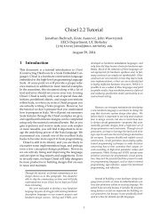
Method 1: Using the complete UNIFAST library (Recommended)<br />
To enable UNIFAST support in a Vivado project environment for the Vivado simulator or<br />
ModelSim, check the Enable fast <strong>simulation</strong> models box, as shown in Figure 2-1.<br />
X-Ref Target - Figure 2-1<br />
Figure 2-1:<br />
See the Encrypted Component Files, page 15 for more information regarding component<br />
files.<br />
For IES and VCS simulators, point to the UNIFAST library using:<br />
-y ../verilog/src/unifast<br />
Simulation Settings: Compilation<br />
For more information, see the appropriate third-party <strong>simulation</strong> user guide.<br />
Logic Simulation www.xilinx.com<br />
Send Feedback<br />
22<br />
UG900 (v2014.1) April 23, 2014
Chapter 2: Understanding Simulation Components in Vivado<br />
Method 2: Using specific UNIFAST modules<br />
To specify individual library components, Verilog configuration statements are used.<br />
Specify the following in the config.v file:<br />
• The name of the top-level module or configuration: (for example: config<br />
cfg_xilinx;)<br />
• The name to which the design configuration applies: (for example: design test<br />
bench;)<br />
• The library search order for cells or instances that are not explicitly called out: (for<br />
example: default liblist unisims_ver unifast_ver;)<br />
• The map for a particular CELL or INSTANCE to a particular library.<br />
(For example: instance testbench.inst.O1 use unifast_ver.MMCME2;)<br />
Note: For ModelSim (vsim) only - genblk gets added to hierarchy name. For example: instance<br />
testbench.genblk1.inst.genblk1.O1 use unifast_ver.MMCME2; - VSIM)<br />
Example config.v<br />
config cfg_xilinx;<br />
design testbench;<br />
default liblist unisims_ver unifast_ver;<br />
//Use fast MMCM for all MMCM blocks in design<br />
cell MMCME2 use unifast_ver.MMCME2;<br />
//use fast dSO48E1for only this specific instance in the design<br />
instance testbench.inst.O1 use unifast_ver.DSP48E1;<br />
//If using ModelSim or Questa, add in the genblk to the name<br />
(instance testbench.genblk1.inst.genblk1.O1 use unifast_ver.DSP48E1)<br />
endconfig<br />
Logic Simulation www.xilinx.com<br />
Send Feedback<br />
23<br />
UG900 (v2014.1) April 23, 2014
Chapter 2: Understanding Simulation Components in Vivado<br />
Using VHDL UNIFAST Library<br />
The VHDL UNIFAST library has the same basic structure as Verilog and can be used with<br />
architectures or libraries. You can include the library in the test bench file. The following<br />
example uses a drill-down hierarchy with a for call:<br />
library unisim;<br />
library unifast;<br />
configuration cfg_xilinx of testbench<br />
is for xilinx<br />
.. for inst:netlist<br />
. . . use entity work.netlist(inst);<br />
.......for inst<br />
.........for all:MMCME2<br />
..........use entity unifast.MMCME2;<br />
.........end for;<br />
.......for O1 inst:DSP48E1;<br />
.........use entity unifast.DSP48E1;<br />
.......end for;<br />
...end for;<br />
..end for;<br />
end for;<br />
end cfg_xilinx;<br />
Compiling Simulation Libraries<br />
IMPORTANT: Because the Vivado simulator has precompiled libraries, it is not necessary for you to<br />
identify the library locations.<br />
Before you can simulate your design using a third-party <strong>simulation</strong> tool, you must compile<br />
the libraries and map the <strong>logic</strong>al library names to the physical library location.<br />
Xilinx provides the compile_simlib Tcl command to automate that task. This Tcl<br />
command provides many options including: target <strong>simulation</strong> tool, language, architecture,<br />
and more. For complete details on this command, please see the Vivado Design Suite Tcl<br />
Command Reference Guide (UG835) [Ref 6] or use -help on the Tcl command line.<br />
To compile Xilinx HDL-based <strong>simulation</strong> libraries for third-party <strong>simulation</strong> vendors, use the<br />
following Tcl command:<br />
compile_simlib<br />
Examples of compile_simlib Tcl commands include:<br />
compile_simlib -simulator modelsim<br />
Libraries are typically compiled (or recompiled) anytime a new simulator version is installed,<br />
when you update to a new version of the Vivado IDE, or when any library source files are<br />
modified (either by you or by a software patch).<br />
Logic Simulation www.xilinx.com<br />
Send Feedback<br />
24<br />
UG900 (v2014.1) April 23, 2014
Chapter 2: Understanding Simulation Components in Vivado<br />
Changing compile_simlib Defaults<br />
The config_compile_simlib Tcl command lets you configure third-party simulator<br />
options for use by the compile_simlib command.<br />
• Tcl Command:<br />
config_compile_simlib [-cfgopt ] [-simulator ] [-reset] [-quiet] [-verbose]<br />
Where:<br />
° - cfgopt : Configuration option in form of<br />
simulator:language:library:options<br />
° -simulator: The name of the simulator whose configuration you want<br />
° -reset: Lets you reset all previous configurations for the specified simulator<br />
° -quiet: Executes the command without any display to the Tcl Console.<br />
° -verbose: Executes the command with all command output to the Tcl Console.<br />
For example, to change the option used to compile the UNISIM VHDL library, type:<br />
config_compile_simlib {cxl.modelsim.vhdl.unisim:-source -93 -novopt}<br />
IMPORTANT: The compile_simlib option compiles only Xilinx primitives. Simulation models of<br />
Xilinx Vivado IP cores are delivered as an output product when the IP is generated; consequently they<br />
are not included in the pre-compiled libraries created using compile_simlib.<br />
Understanding the Simulator Language Option<br />
Most Xilinx IP deliver behavioral <strong>simulation</strong> models for a single language only, effectively<br />
disabling <strong>simulation</strong> for language-locked simulators if you are not licensed for the<br />
appropriate language. The simulator_language property ensures that an IP delivers a<br />
<strong>simulation</strong> model for any given language. ( Figure 3-3, page 45 shows the location at which<br />
you can set the simulator language.)<br />
The Vivado Design Suite ensures the availability of a <strong>simulation</strong> model by using the<br />
available synthesis files of an IP to generate a language-specific structural <strong>simulation</strong><br />
model on demand. For cases in which a behavioral model is missing or does not match the<br />
licensed <strong>simulation</strong> language, the Vivado tools automatically generate a structural<br />
<strong>simulation</strong> model to enable <strong>simulation</strong>. Otherwise, the existing behavioral <strong>simulation</strong> model<br />
for the IP is used. If no synthesis or <strong>simulation</strong> files exist, <strong>simulation</strong> is not supported.<br />
Note: The simulator_language property cannot deliver a language-specific <strong>simulation</strong> netlist file if<br />
the generated Synthesized checkpoint (.dcp) is disabled.<br />
Logic Simulation www.xilinx.com<br />
Send Feedback<br />
25<br />
UG900 (v2014.1) April 23, 2014
Chapter 2: Understanding Simulation Components in Vivado<br />
1. Click Window > IP Catalog.<br />
2. Right-click the appropriate IP and select IP Settings from the popup menu.<br />
3. Click Customize IP.<br />
4. In the Customize IP dialog box, click OK.<br />
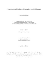
The Generate Output Products dialog box (shown in the figure below) appears.<br />
X-Ref Target - Figure 2-2<br />
Table 2-6:<br />
Figure 2-2:<br />
Dialog Box Showing Generate Synthesized Checkpoint (.dcp) Option<br />
The table below illustrates the function of the simulator_language property.<br />
Function of simulator_language Property<br />
IP Delivered Simulation Model simulator_language Value Simulation Model Used<br />
IP delivers VHDL and Verilog behavioral<br />
models<br />
Mixed<br />
Verilog<br />
VHDL<br />
Behavioral model (target_language)<br />
Verilog behavioral model<br />
VHDL behavioral model<br />
IP delivers Verilog behavioral model only Mixed Verilog behavioral model<br />
Verilog<br />
VHDL<br />
Verilog behavioral model<br />
VHDL <strong>simulation</strong> netlist generated<br />
from DCP<br />
Logic Simulation www.xilinx.com<br />
Send Feedback<br />
26<br />
UG900 (v2014.1) April 23, 2014
Chapter 2: Understanding Simulation Components in Vivado<br />
Table 2-6: Function of simulator_language Property (Cont’d)<br />
IP Delivered Simulation Model simulator_language Value Simulation Model Used<br />
IP delivers VHDL behavioral model only Mixed VHDL behavioral model<br />
Verilog<br />
VHDL<br />
Verilog <strong>simulation</strong> netlist generated<br />
from DCP<br />
VHDL behavioral model<br />
IP delivers no behavioral models Mixed, Verilog, VHDL Netlist generated from DCP<br />
(target_language)<br />
Notes:<br />
- Where available, behavioral <strong>simulation</strong> models always take precedence over structural <strong>simulation</strong><br />
models. The Vivado tools select behavioral or structural models automatically, based on model<br />
availability. It is not possible to override the automated selection.<br />
- The target_language property is used when either language could be used for <strong>simulation</strong><br />
TCL: set_property target_language VHDL [current_project]<br />
Using the export_<strong>simulation</strong> Command<br />
The export_<strong>simulation</strong> command lets you generate a standalone run file for IES and<br />
VCS.<br />
The command exports a script and any associated data files for driving standalone<br />
<strong>simulation</strong> using the specified simulator.<br />
When you run this command on the Vivado Tcl Console, ensure that switches are specified<br />
in the following order:<br />
export_<strong>simulation</strong> -of_objects -lib_map_path <br />
-script_name [-absolute_path] [-32bit] [-force] -directory -simulator<br />
[-quiet] [-verbose]<br />
The command returns: true (0) if successful; otherwise false (1)<br />
Where:<br />
° [-of_objects]<br />
Provides an export <strong>simulation</strong> script for the specified set of objects. The default set<br />
of objects is the active <strong>simulation</strong> top.<br />
° [-lib_map_path]<br />
The precompiled <strong>simulation</strong> library directory path. If not specified, follow the<br />
instructions in the generated script header to manually provide the <strong>simulation</strong><br />
library mapping information.<br />
° [-script_name]<br />
Optional. The output shell script file name. If not specified, a file with a default<br />
name is created with the .sh extension.<br />
Logic Simulation www.xilinx.com<br />
Send Feedback<br />
27<br />
UG900 (v2014.1) April 23, 2014
Chapter 2: Understanding Simulation Components in Vivado<br />
° [-absolute_path]<br />
Makes all file paths absolute.<br />
° [-32bit]<br />
Performs 32-bit compilation.<br />
° [-force]<br />
Overwrites previous files.<br />
° -directory<br />
Directory to export the <strong>simulation</strong> script.<br />
° -simulator<br />
Simulator for which to create the <strong>simulation</strong> script (: ies|vcs_mx).<br />
° [-quiet]<br />
Ignores command errors.<br />
° [-verbose]<br />
Suspends message limits during command execution.<br />
Examples:<br />
The following command generates a <strong>simulation</strong> script file in the current directory for the<br />
IES simulator. The source file paths in the generated script are relative to the current<br />
directory:<br />
export_<strong>simulation</strong> -simulator ies -directory "."<br />
The following command generates a script file accum_0_sim_ies.sh for the accum_0 IP<br />
in the specified output directory for the IES simulator:<br />
export_<strong>simulation</strong> -of_objects [get_files accum_0.xci] -simulator ies -directory<br />
"test_sim"<br />
The following command generates a script file accum_0_sim_vcs_mx.sh for the<br />
accum_0 IP in the specified output directory for the VCS_MX simulator:<br />
export_<strong>simulation</strong> -of_objects [get_ips accum_0] -simulator vcs_mx -directory<br />
"test_sim"<br />
The following command includes /sim_libs/ius/lin64/lib/cds.lib file path in the<br />
./test_sim/cds.lib file ("INCLUDE /sim_libs/ius/lin64/lib/cds.lib") for<br />
referencing the compiled libraries for IES simulator:-<br />
export_<strong>simulation</strong> -lib_map_path "/sim_libs/ius/lin64/lib" -simulator ies -directory<br />
"test_sim"<br />
Logic Simulation www.xilinx.com<br />
Send Feedback<br />
28<br />
UG900 (v2014.1) April 23, 2014
Chapter 2: Understanding Simulation Components in Vivado<br />
Recommended Simulation Resolution<br />
IMPORTANT: Run <strong>simulation</strong>s using a time resolution of 1 ps. Some Xilinx primitive components, such<br />
as MMCM, require a 1 ps resolution to work properly in either functional or timing <strong>simulation</strong>.<br />
There is no simulator performance gain achieved through use of coarser resolution with the<br />
Xilinx <strong>simulation</strong> models. (In Xilinx <strong>simulation</strong> models, most <strong>simulation</strong> time is spent in delta<br />
cycles, and delta cycles are not affected by simulator resolution.)<br />
IMPORTANT: Picoseconds are used as the minimum resolution because testing equipment can measure<br />
timing only to the nearest picosecond resolution.<br />
Generating a Netlist<br />
To run <strong>simulation</strong> of a synthesized or implemented design run the netlist generation process.<br />
The netlist generation Tcl commands can take a synthesized or implemented design<br />
database and write out a single netlist for the entire design.<br />
Netlist generation Tcl commands can write SDF and the design netlist. The Vivado Design<br />
Suite provides the following:<br />
• Tcl Commands:<br />
° write_verilog: Verilog netlist<br />
° write_vhdl: VHDL netlist<br />
° write_sdf: SDF generation<br />
TIP: The SDF values are only estimates early in the design process (for example, during synthesis) As<br />
the design process progresses, the accuracy of the timing numbers also progress when there is more<br />
information available in the database.<br />
Generating a Functional Netlist<br />
The Vivado Design Suite supports writing out a Verilog or VHDL structural netlist for<br />
functional <strong>simulation</strong>. The purpose of this netlist is to run <strong>simulation</strong> (without timing) to<br />
check that the behavior of the structural netlist matches the expected behavioral model<br />
(RTL) <strong>simulation</strong>.<br />
The functional <strong>simulation</strong> netlist is a hierarchical, folded netlist that is expanded to the<br />
primitive module or entity level; the lowest level of hierarchy consists of primitives and<br />
macro primitives.<br />
Logic Simulation www.xilinx.com<br />
Send Feedback<br />
29<br />
UG900 (v2014.1) April 23, 2014
Chapter 2: Understanding Simulation Components in Vivado<br />
These primitives are contained in the following libraries:<br />
• UNISIMS_VER <strong>simulation</strong> library for Verilog <strong>simulation</strong><br />
• UNISIMS <strong>simulation</strong> library for VHDL <strong>simulation</strong><br />
In many cases, you can use the same test bench that you used for behavioral <strong>simulation</strong> to<br />
perform a more accurate <strong>simulation</strong>.<br />
The following Tcl commands generate Verilog and VHDL functional <strong>simulation</strong> netlist,<br />
respectively:<br />
write_verilog -mode funcsim <br />
write_vhdl -mode funcsim <br />
Generating a Timing Netlist<br />
You can use a Verilog timing <strong>simulation</strong> to verify circuit operation after the Vivado tools<br />
have calculated the worst-case placed and routed delays.<br />
In many cases, you can use the same test bench that you used for functional <strong>simulation</strong> to<br />
perform a more accurate <strong>simulation</strong>.<br />
Compare the results from the two <strong>simulation</strong>s to verify that your design is performing as<br />
initially specified.<br />
There are two steps to generating a timing <strong>simulation</strong> netlist:<br />
1. Generate a <strong>simulation</strong> netlist file for the design.<br />
2. Generate an SDF delay file with all the timing delays annotated.<br />
IMPORTANT: Vivado IDE supports Verilog timing <strong>simulation</strong> only.<br />
The following is the syntax for generating a timing <strong>simulation</strong> netlist:<br />
• Tcl Command:<br />
write_verilog -mode timesim -sdf_anno true <br />
Annotating the SDF File<br />
Based on the specified process corner, the SDF file contains different min and max numbers.<br />
RECOMMENDED: Run two separate <strong>simulation</strong>s to check for setup and hold violations.<br />
To run a setup check, create an SDF file with -process corner slow, and use the max<br />
column from the SDF file.<br />
Logic Simulation www.xilinx.com<br />
Send Feedback<br />
30<br />
UG900 (v2014.1) April 23, 2014
Chapter 2: Understanding Simulation Components in Vivado<br />
To run a hold check, create an SDF file with the -process corner fast, and use the min<br />
column from the SDF file. The method for specifying which SDF delay field to use is<br />
dependent on the <strong>simulation</strong> tool you are using. Refer to the specific <strong>simulation</strong> tool<br />
documentation for information on how to set this option.<br />
To get full coverage run all four timing <strong>simulation</strong>s, specify as follows:<br />
° Slow corner: SDFMIN and SDFMAX<br />
° Fast corner: SDFMIN and SDFMAX<br />
Using Global Reset and 3-State<br />
Xilinx devices have dedicated routing and circuitry that connect to every register in the<br />
device.<br />
Global Set and Reset Net<br />
During configuration, the dedicated Global Set/Reset (GSR) signal is asserted. The GSR<br />
signal is deasserted upon completion of device configuration. All the flip-flops and latches<br />
receive this reset, and are set or reset depending on how the registers are defined.<br />
RECOMMENDED: Although you can access the GSR net after configuration, recommends avoiding use<br />
of the GSR circuitry in place of a manual reset. This is because the FPGA devices offer high-speed<br />
backbone routing for high fanout signals such as a system reset. This backbone route is faster than the<br />
dedicated GSR circuitry, and is easier to analyze than the dedicated global routing that transports the<br />
GSR signal.<br />
In post-synthesis and post-implementation <strong>simulation</strong>s, the GSR signal is automatically<br />
asserted for the first 100 ns to simulate the reset that occurs after configuration.<br />
A GSR pulse can optionally be supplied in pre-synthesis functional <strong>simulation</strong>s, but is not<br />
necessary if the design has a local reset that resets all registers.<br />
TIP: When you create a test bench, remember that the GSR pulse occurs automatically in the<br />
post-synthesis and post-implementation <strong>simulation</strong>. This holds all registers in reset for the first 100 ns<br />
of the <strong>simulation</strong>.<br />
Global 3-State Net<br />
In addition to the dedicated global GSR, output buffers are set to a high impedance state<br />
during configuration mode with the dedicated Global 3-state (GTS) net. All<br />
general-purpose outputs are affected whether they are regular, 3-state, or bidirectional<br />
Logic Simulation www.xilinx.com<br />
Send Feedback<br />
31<br />
UG900 (v2014.1) April 23, 2014
Chapter 2: Understanding Simulation Components in Vivado<br />
outputs during normal operation. This ensures that the outputs do not erroneously drive<br />
other devices as the FPGA is configured.<br />
In <strong>simulation</strong>, the GTS signal is usually not driven. The circuitry for driving GTS is available<br />
in the post-synthesis and post-implementation <strong>simulation</strong>s and can be optionally added for<br />
the pre-synthesis functional <strong>simulation</strong>, but the GTS pulse width is set to 0 by default.<br />
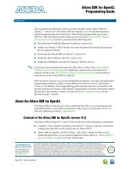
Using Global 3-State and Global Set and Reset Signals<br />
Figure 2-3 shows how Global 3-State (GTS) and Global Set/Reset (GSR) signals are used in<br />
an FPGA.<br />
X-Ref Target - Figure 2-3<br />
<br />
<br />
<br />
<br />
<br />
<br />
<br />
<br />
<br />
<br />
<br />
<br />
<br />
<br />
<br />
<br />
<br />
<br />
<br />
<br />
<br />
<br />
<br />
<br />
<br />
<br />
<br />
<br />
<br />
<br />
<br />
<br />
<br />
<br />
<br />
<br />
Figure 2-3:<br />
Built-in FPGA Initialization Circuitry Diagram<br />
Global Set and Reset and Global 3-State Signals in Verilog<br />
The GSR and GTS signals are defined in the<br />
/data/verilog/src/glbl.v module.<br />
In most cases, GSR and GTS need not be defined in the test bench.<br />
The glbl.v file declares the global GSR and GTS signals and automatically pulses GSR for<br />
100 ns.<br />
Global Set and Reset and Global 3-State Signals in VHDL<br />
The GSR and GTS signals are defined in the file:<br />
/data/vhdl/src/unisims/primitive/GLBL_VHD.vhd.<br />
To use the GLBL_VHD component you must instantiate it into the test bench.<br />
The GLBL_VHD component declares the global GSR and GTS signals and automatically<br />
pulses GSR for 100 ns.<br />
Logic Simulation www.xilinx.com<br />
Send Feedback<br />
32<br />
UG900 (v2014.1) April 23, 2014
Chapter 2: Understanding Simulation Components in Vivado<br />
The following code snippet shows an example of instantiating the GLBL_VHD component in<br />
the test bench and changing the assertion pulse width of the Reset on Configuration (ROC)<br />
to 90 ns:<br />
GLBL_VHD inst:GLBL_VHD generic map (ROC_WIDTH => 90000);<br />
Delta Cycles and Race Conditions<br />
This user guide describes event-based simulators. Event-based simulators can process<br />
multiple events at a given <strong>simulation</strong> time. While these events are being processed, the<br />
simulator cannot advance the <strong>simulation</strong> time. This event processing time is commonly<br />
referred to as delta cycles. There can be multiple delta cycles in a given <strong>simulation</strong> time step.<br />
Simulation time is advanced only when there are no more transactions to process. For this<br />
reason, simulators can give unexpected results, depending on when the events are<br />
scheduled within a time step. The following VHDL coding example shows how an<br />
unexpected result can occur.<br />
VHDL Coding Example With Unexpected Results<br />
clk_b
Chapter 2: Understanding Simulation Components in Vivado<br />
• Force a delta delay by using a temporary signal, as shown in the following example:<br />
clk_b
Chapter 2: Understanding Simulation Components in Vivado<br />
Disabling X Propagation for Synchronous Elements<br />
When a timing violation occurs during a timing <strong>simulation</strong>, the default behavior of a latch,<br />
register, RAM, or other synchronous elements is to output an X to the simulator. This occurs<br />
because the actual output value is not known. The output of the register could:<br />
• Retain its previous value<br />
• Update to the new value<br />
• Go metastable, in which a definite value is not settled upon until some time after the<br />
clocking of the synchronous element<br />
Because this value cannot be determined, and accurate <strong>simulation</strong> results cannot be<br />
guaranteed, the element outputs an X to represent an unknown value. The X output remains<br />
until the next clock cycle in which the next clocked value updates the output if another<br />
violation does not occur.<br />
The presence of an X output can significantly affect <strong>simulation</strong>. For example, an X generated<br />
by one register can be propagated to others on subsequent clock cycles. This can cause<br />
large portions of the design under test to become unknown.<br />
Correcting X-Generation<br />
To correct X-generation:<br />
• On a synchronous path, analyze the path and fix any timing problems associated with<br />
this or other paths to ensure a properly operating circuit.<br />
• On an asynchronous path, if you cannot otherwise avoid timing violations, disable the<br />
X propagation on synchronous elements during timing violations by the method<br />
described in Using the ASYNC_REG Constraint, page 34.<br />
When X propagation is disabled, the previous value is retained at the output of the register.<br />
In the actual silicon, the register might have changed to the 'new' value. Disabling X<br />
propagation might yield <strong>simulation</strong> results that do not match the silicon behavior.<br />
CAUTION! Exercise care when using this option. Use it only if you cannot otherwise avoid timing<br />
violations.<br />
Simulating Configuration Interfaces<br />
This section describes the <strong>simulation</strong> of the following configuration interfaces:<br />
• JTAG <strong>simulation</strong><br />
• SelectMAP <strong>simulation</strong><br />
Logic Simulation www.xilinx.com<br />
Send Feedback<br />
35<br />
UG900 (v2014.1) April 23, 2014
Chapter 2: Understanding Simulation Components in Vivado<br />
JTAG Simulation<br />
BSCAN component <strong>simulation</strong> is supported on all devices.<br />
The <strong>simulation</strong> supports the interaction of the JTAG ports and some of the JTAG operation<br />
commands. The JTAG interface, including interface to the scan chain, is not fully supported.<br />
To simulate this interface:<br />
1. Instantiate the BSCANE2 component and connect it to the design.<br />
2. Instantiate the JTAG_SIME2 component into the test bench (not the design).<br />
This becomes:<br />
• The interface to the external JTAG signals (such as TDI, TDO, and TCK)<br />
• The communication channel to the BSCAN component<br />
The communication between the components takes place in the VPKG VHDL package file or<br />
the glbl Verilog global module. Accordingly, no implicit connections are necessary between<br />
the specific JTAG_SIME2 component and the design, or the specific BSCANE2 symbol.<br />
Stimulus can be driven and viewed from the specific JTAG_SIME2 component within the<br />
test bench to understand the operation of the JTAG/BSCAN function. Instantiation<br />
templates for both of these components are available in both the Vivado Design Suite<br />
templates and the specific-device libraries guides.<br />
SelectMAP Simulation<br />
The configuration <strong>simulation</strong> model (SIM_CONFIGE2) with an instantiation template allows<br />
supported configuration interfaces to be simulated to ultimately show the DONE pin going<br />
HIGH. This is a model of how the supported devices react to stimulus on the supported<br />
configuration interface.<br />
Table 2-7 lists the supported interfaces and devices.<br />
Table 2-7:<br />
Supported Configuration Devices and Modes<br />
Devices SelectMAP Serial SPI BPI<br />
7 Series and<br />
Zynq ® -7000 AP SoC<br />
Devices<br />
Yes Yes No No<br />
The model handles control signal activity as well as bit file downloading. Internal register<br />
settings such as the CRC, IDCODE, and status registers are included. You can monitor the<br />
Sync Word as it enters the device and the start-up sequence as it progresses. Figure 2-4,<br />
below, illustrates how the system should map from the hardware to the <strong>simulation</strong><br />
environment.<br />
Logic Simulation www.xilinx.com<br />
Send Feedback<br />
36<br />
UG900 (v2014.1) April 23, 2014
Chapter 2: Understanding Simulation Components in Vivado<br />
The configuration process is specifically outlined in the configuration user guides for each<br />
device. These guides contain information on the configuration sequence, as well as the<br />
configuration interfaces.<br />
X-Ref Target - Figure 2-4<br />
<br />
<br />
<br />
<br />
<br />
<br />
<br />
<br />
<br />
<br />
<br />
<br />
<br />
<br />
<br />
<br />
<br />
<br />
<br />
<br />
<br />
Figure 2-4:<br />
Block Diagram of Model Interaction<br />
System Level Description<br />
The SIM_CONFIGE2 model allows the configuration interface control <strong>logic</strong> to be tested<br />
before the hardware is available. It simulates the entire device, and is used at a system level<br />
for:<br />
• Applications using a processor to control the configuration <strong>logic</strong> to ensure proper<br />
wiring, control signal handling, and data input alignment.<br />
• Applications that control the data loading process with the CS (SelectMAP Chip Select)<br />
or CLK signal to ensure proper data alignment.<br />
• Systems that need to perform a SelectMAP ABORT or Readback.<br />
The ZIP file associated with this model is located at:<br />
http://www.xilinx.com/txpatches/pub/documentation/misc/config_test_bench.zip<br />
The ZIP file has sample test benches that simulate a processor running the SelectMAP <strong>logic</strong>.<br />
These test benches have control <strong>logic</strong> to emulate a processor controlling the SelectMAP<br />
interface, and include features such as a full configuration, ABORT, and Readback of the<br />
IDCODE and status registers.<br />
The simulated host system must have a method for file delivery as well as control signal<br />
management. These control systems should be designed as set forth in the device<br />
configuration user guides.<br />
The SIM_CONFIGE2 model also demonstrates what is occurring inside the device during the<br />
configuration procedure when a BIT file is loaded into the device.<br />
Logic Simulation www.xilinx.com<br />
Send Feedback<br />
37<br />
UG900 (v2014.1) April 23, 2014
Chapter 2: Understanding Simulation Components in Vivado<br />
During the BIT file download, the model processes each command and changes registers<br />
settings that mirror the hardware changes.<br />
You can monitor the CRC register as it actively accumulates a CRC value. The model also<br />
shows the Status Register bits being set as the device progresses through the different<br />
states of configuration.<br />
Debugging with the Model<br />
The SIM_CONFIGE2 model provides an example of a correct configuration. You can<br />
leverage this example to assist in the debug procedure if you encounter device<br />
programming issues.<br />
You can read the Status Register through JTAG using the Vivado Device Programmer tool.<br />
This register contains information relating to the current status of the device and is a useful<br />
debugging resource. If you encounter issues on the board, reading the Status Register in<br />
Vivado Device Programmer is one of the first debugging steps to take.<br />
After the status register is read, you can map it to the <strong>simulation</strong> to pinpoint the<br />
configuration stage of the device.<br />
For example, the GHIGH bit is set HIGH after the data load process completes successfully;<br />
if this bit is not set, then the data loading operation did not complete. You can also monitor<br />
the GTW, GWE, and DONE signals set in BitGen that are released in the start-up sequence.<br />
The SIM_CONFIGE2 model also allows for error injection. The active CRC <strong>logic</strong> detects any<br />
issue if the data load is paused and started again with any problems. It also detects bit flips<br />
manually inserted in the BIT file, and handles them just as the device would handle this<br />
error.<br />
Feature Support<br />
Each device-specific configuration user guide outlines the supported methods of<br />
interacting with each configuration interface.The table below shows which features<br />
discussed in the configuration user guides are supported.<br />
The SIM_CONFIGE2 model:<br />
• Does not support Readback of configuration data.<br />
• Does not store configuration data provided, although it does calculate a CRC value.<br />
• Can perform Readback on specific registers only to ensure that a valid command<br />
sequence and signal handling is provided to the device.<br />
• Is not intended to allow Readback data files to be produced.<br />
Logic Simulation www.xilinx.com<br />
Send Feedback<br />
38<br />
UG900 (v2014.1) April 23, 2014
Chapter 2: Understanding Simulation Components in Vivado<br />
Table 2-8: Model-Supported Slave SelectMAP and Serial Features<br />
Slave SelectMAP and Serial Features<br />
Supported<br />
Master mode<br />
No<br />
Daisy chain - slave parallel daisy chains<br />
No<br />
SelectMAP data loading<br />
Continuous SelectMAP data loading<br />
Non-continuous SelectMAP data loading<br />
SelectMAP ABORT<br />
SelectMAP reconfiguration<br />
SelectMAP data ordering<br />
Reconfiguration and MultiBoot<br />
Configuration CRC – CRC checking during configuration<br />
Configuration CRC – post-configuration CRC<br />
Yes<br />
Yes<br />
Yes<br />
Yes<br />
No<br />
Yes<br />
No<br />
Yes<br />
No<br />
Disabling Block RAM Collision Checks for<br />
Simulation<br />
Xilinx block RAM memory is a true dual-port RAM where both ports can access any memory<br />
location at any time. Be sure that the same address space is not accessed for reading and<br />
writing at the same time. This causes a block RAM address collision. These are valid<br />
collisions, because the data that is being read from the read port is not valid.<br />
In the hardware, the value that is read might be the old data, the new data, or a combination<br />
of the old data and the new data.<br />
In <strong>simulation</strong>, this is modeled by outputting X because the value read is unknown. For more<br />
information on block RAM collisions, see the user guide for the device.<br />
In certain applications, this situation cannot be avoided or designed around. In these cases,<br />
the block RAM can be configured not to look for these violations. This is controlled by the<br />
generic (VHDL) or parameter (Verilog) SIM_COLLISION_CHECK string in block RAM<br />
primitives.<br />
Logic Simulation www.xilinx.com<br />
Send Feedback<br />
39<br />
UG900 (v2014.1) April 23, 2014
Chapter 2: Understanding Simulation Components in Vivado<br />
Table 2-9 shows the string options you can use with SIM_COLLISION_CHECK to control<br />
<strong>simulation</strong> behavior in the event of a collision.<br />
Table 2-9:<br />
String<br />
SIM_COLLISION_CHECK Strings<br />
Write Collision<br />
Messages<br />
ALL Yes Yes<br />
Write Xs on the Output<br />
WARNING_ONLY Yes No. Applies only at the time of collision.<br />
Subsequent reads of the same address space could<br />
produce Xs on the output.<br />
GENERATE_X_ONLY No Yes<br />
None No No. Applies only at the time of collision.<br />
Subsequent reads of the same address space could<br />
produce Xs on the output.<br />
Apply the SIM_COLLISION_CHECK at an instance level so you can change the setting for<br />
each block RAM instance.<br />
Dumping the Switching Activity Interchange<br />
Format File for Power Analysis<br />
The Switching Activity Interchange Format (SAIF) is an ASCII report that assists in extracting<br />
and storing switching activity information generated by simulator tools.<br />
This switching activity can be back-annotated into the Xilinx power analysis and<br />
optimization tools for the power measurements and estimations.<br />
See the information about the respective simulator for more detail:<br />
• Vivado simulator: Power Analysis Using Vivado Simulator, page 126<br />
• Dumping SAIF in QuestaSim/ModelSim, page 140<br />
• Dumping SAIF for Power Analysis in IES, page 148<br />
• Dumping SAIF for Power Analysis for VCS, page 155<br />
Logic Simulation www.xilinx.com<br />
Send Feedback<br />
40<br />
UG900 (v2014.1) April 23, 2014
Chapter 3<br />
Using the Vivado Simulator from the<br />
Vivado IDE<br />
Introduction<br />
This chapter describes the Vivado ® simulator features, which are available in the Vivado<br />
Integrated Design Environment (IDE), allowing you to do pushbutton waveform tracing and<br />
debug.<br />
The Vivado simulator is a Hardware Description Language (HDL) event-driven simulator that<br />
supports functional and timing <strong>simulation</strong>s for VHDL, Verilog, and mixed VHDL/Verilog<br />
designs. See the “Important” note on page 60 for timing <strong>simulation</strong> support information.<br />
See Vivado Design Suite Tutorial: Logic Simulation (UG937) [Ref 8] for a step-by-step<br />
demonstration of how to run Vivado <strong>simulation</strong>.<br />
Vivado Simulator Features<br />
The Vivado simulator supports the following features:<br />
• Source code debugging<br />
• SDF annotation<br />
• VCD dumping<br />
• SAIF dumping for power analysis and optimization<br />
• Native support for HardIP blocks (such as serial transceivers and PCIe ® )<br />
• Multi-threaded compilation<br />
• Mixed language (VHDL and Verilog) use<br />
• Single-click <strong>simulation</strong> re-compile and re-launch<br />
• One-click compilation and <strong>simulation</strong><br />
• Built-in support for Xilinx ® <strong>simulation</strong> libraries<br />
• Real-time waveform update<br />
Logic Simulation www.xilinx.com<br />
Send Feedback<br />
41<br />
UG900 (v2014.1) April 23, 2014
Chapter 3: Using the Vivado Simulator from the Vivado IDE<br />
Adding or Creating Simulation Source Files<br />
To add <strong>simulation</strong> sources to a Vivado Design Suite project:<br />
1. Select File > Add Sources, or click Add Sources.<br />
The Add Sources wizard opens.<br />
2. Select Add or Create Simulation Sources, and click Next.<br />
The Add or Create Simulation Sources dialog box opens. The options are:<br />
° Specify Simulation Set: Enter the name of the <strong>simulation</strong> set in which to store<br />
<strong>simulation</strong> sources (the default is sim_1, sim_2, and so forth).<br />
You can select the Create Simulation Set command from the drop-down menu to<br />
define a new <strong>simulation</strong> set. When more than one <strong>simulation</strong> set is available, the<br />
Vivado simulator shows which <strong>simulation</strong> set is the active (currently used) set.<br />
For a demonstration of this feature, see the Quick Take Video at<br />
www.xilinx.com/training/<strong>vivado</strong>/index.htm.<br />
° Add Files: Invokes a file browser so you can select <strong>simulation</strong> source files to add to<br />
the project.<br />
° Add Directories: Invokes directory browser to add all <strong>simulation</strong> source files from<br />
the selected directories. Files in the specified directory with valid source file<br />
extensions are added to the project.<br />
° Create File: Invokes the Create Source File dialog box where you can create new<br />
<strong>simulation</strong> source files. See the Vivado Design Suite User Guide: Using the Vivado IDE<br />
(UG893) [Ref 2] for more information about project source files.<br />
° Buttons on the side of the dialog box let you do the following:<br />
- Remove: Removes the selected source files from the list of files to be added.<br />
- Move Selected File Up: Moves the file up in the list order.<br />
- Move Selected File Down: Moves the file down in the list order.<br />
° Check boxes in the wizard provide the following options:<br />
- Scan and add RTL include files into project: Scans the added RTL file and adds<br />
any referenced include files.<br />
- Copy sources into project: Copies the original source files into the project and<br />
uses the local copied version of the file in the project.<br />
Logic Simulation www.xilinx.com<br />
Send Feedback<br />
42<br />
UG900 (v2014.1) April 23, 2014
Chapter 3: Using the Vivado Simulator from the Vivado IDE<br />
If you elected to add directories of source files using the Add Directories<br />
command, the directory structure is maintained when the files are copied locally<br />
into the project.<br />
- Add sources from subdirectories: Adds source files from the subdirectories of<br />
directories specified in the Add Directories option.<br />
- Include all design sources for <strong>simulation</strong>: Includes all the design sources for<br />
<strong>simulation</strong>.<br />
Working with Simulation Sets<br />
The Vivado IDE stores <strong>simulation</strong> source files in <strong>simulation</strong> sets that display in folders in the<br />
Sources window, and are either remotely referenced or stored in the local project directory.<br />
The <strong>simulation</strong> set lets you define different sources for different stages of the design. For<br />
example, there can be one test bench source to provide stimulus for behavioral <strong>simulation</strong><br />
of the elaborated design or a module of the design, and a different test bench to provide<br />
stimulus for timing <strong>simulation</strong> of the implemented design.<br />
When adding <strong>simulation</strong> sources to the project, you can specify which <strong>simulation</strong> source set<br />
to use.<br />
To edit a <strong>simulation</strong> set:<br />
1. In the Sources window popup menu, select Simulation Sources > Edit Simulation<br />
Sets, as shown in Figure 3-1.<br />
X-Ref Target - Figure 3-1<br />
Figure 3-1:<br />
Edit Simulation Sets Option<br />
The Add or Create Simulation Sources wizard opens.<br />
Logic Simulation www.xilinx.com<br />
Send Feedback<br />
43<br />
UG900 (v2014.1) April 23, 2014
Chapter 3: Using the Vivado Simulator from the Vivado IDE<br />
2. From the Add or Create Simulation Sources wizard, select Add Files.<br />
This adds the sources associated with the project to the newly-created <strong>simulation</strong> set.<br />
3. Add additional files as needed.<br />
The selected <strong>simulation</strong> set is used for the active design run.<br />
Using Simulation Settings<br />
The Flow Navigator > Simulation > Simulation Settings section lets you configure the<br />
<strong>simulation</strong> settings in Vivado IDE. The Flow Navigator Simulation section is shown in<br />
Figure 3-2.<br />
X-Ref Target - Figure 3-2<br />
Figure 3-2:<br />
Flow Navigator Simulation Options<br />
• Simulation Settings: Opens the Simulation Settings dialog box where you can select<br />
and configure the Vivado simulator.<br />
• Run Simulation: Sets up the command options to compile, elaborate, and simulate the<br />
design based on the <strong>simulation</strong> settings, then launches the Vivado simulator. When you<br />
run <strong>simulation</strong> prior to synthesizing the design, the Vivado simulator runs a behavioral<br />
<strong>simulation</strong>, and opens a waveform window, (see Figure 3-12, page 56) that shows the<br />
HDL objects with the signal and bus values in either digital or analog form.<br />
At each design step (both after you have successfully synthesized and after<br />
implementing the design) you can run a functional <strong>simulation</strong> and timing <strong>simulation</strong>.<br />
To use the corresponding Tcl command, type: launch_xsim<br />
TIP: This command has a -scripts_only option that writes a script to run the Vivado simulator.<br />
Logic Simulation www.xilinx.com<br />
Send Feedback<br />
44<br />
UG900 (v2014.1) April 23, 2014
Chapter 3: Using the Vivado Simulator from the Vivado IDE<br />
When you select Simulation Settings, the Project Settings dialog box opens, as shown in<br />
Figure 3-3.<br />
X-Ref Target - Figure 3-3<br />
Figure 3-3:<br />
Simulation Settings Dialog Box<br />
IMPORTANT: The compilation and <strong>simulation</strong> settings for a previously defined <strong>simulation</strong> set are not<br />
applied to a newly-defined <strong>simulation</strong> set.<br />
Logic Simulation www.xilinx.com<br />
Send Feedback<br />
45<br />
UG900 (v2014.1) April 23, 2014
Chapter 3: Using the Vivado Simulator from the Vivado IDE<br />
Simulation Dialog Box Options<br />
Navigation: Flow Navigator > Simulation > Simulation Settings<br />
Note: Available options in the dialog box are based on the target simulator selected.<br />
Target simulator<br />
Specifies the simulator to be launched for behavioral or timing <strong>simulation</strong>. The available<br />
options are:<br />
• Vivado Simulator: Specifies the target simulator is the Vivado simulator.<br />
IMPORTANT: Because the Vivado simulator has precompiled libraries, it is not necessary to identify the<br />
library locations.<br />
• QuestaSim/ModelSim: Specifies that QuestaSim/ModelSim is the target simulator.<br />
See Chapter 7, Simulating with QuestaSim/ModelSim for third-party <strong>simulation</strong><br />
information.<br />
Simulator language<br />
• Options are VHDL, Verilog, or Mixed.<br />
Simulation set<br />
• Selects the active <strong>simulation</strong> set using an existing <strong>simulation</strong> set or by using the Create<br />
<strong>simulation</strong> set option, described in Working with Simulation Sets, page 43.<br />
Simulation top module name<br />
• Sets the <strong>simulation</strong> top module.<br />
Clean up <strong>simulation</strong> files (check box)<br />
Selects the option to delete all content of the \simset <strong>simulation</strong> directory prior to<br />
running the <strong>simulation</strong>.<br />
Generate scripts only (check box)<br />
Sets the option to generate only the target simulator project and scripts. When selected, the<br />
<strong>simulation</strong> tool is not launched, and <strong>simulation</strong> is not performed.<br />
Logic Simulation www.xilinx.com<br />
Send Feedback<br />
46<br />
UG900 (v2014.1) April 23, 2014
Chapter 3: Using the Vivado Simulator from the Vivado IDE<br />
Compiled library location<br />
Selects the precompiled library location when QuestaSim or ModelSim is the target<br />
simulator.<br />
- See the Using Xilinx Simulation Libraries, page 13 for information about how to<br />
specify <strong>simulation</strong> libraries.<br />
- See Chapter 7, Simulating with QuestaSim/ModelSim, for more information<br />
regarding QuestaSim/ModelSim.<br />
Compilation Tab<br />
Navigation: Flow Navigator > Simulation > Simulation Settings > Simulation Dialog<br />
Box > Simulation tab<br />
Shown in the figure below, the Compilation tab provides the frequently-used compilation<br />
options based on the selected target simulator.<br />
X-Ref Target - Figure 3-4<br />
Figure 3-4:<br />
• Verilog options: Provides the option to specify file search paths and ‘define values.<br />
• Generics/Parameters options: Provides the option to set and override top-level<br />
generic/parameter values.<br />
• Command options:<br />
Project Settings, Simulation Dialog Box, Compilation Tab<br />
° -debug: Sets the <strong>simulation</strong> debug visibility level. Is set to typical by default for a<br />
faster <strong>simulation</strong> run. Other options are off and all. The typical setting includes<br />
wave and line options.<br />
Logic Simulation www.xilinx.com<br />
Send Feedback<br />
47<br />
UG900 (v2014.1) April 23, 2014
Chapter 3: Using the Vivado Simulator from the Vivado IDE<br />
° -mt: Is set to auto by default. This option lets you specify the number of<br />
sub-compilation job to run in parallel. When you select the option, a drop-down<br />
menu displays the following selections, as shown in Figure 3-4, above: off, 2, 4, 8,<br />
16, and 32.<br />
You can also set the -mt level using the Tcl command:<br />
set_property XELAB.MT_LEVEL off [get_filesets sim_1]<br />
° SDF Delay:<br />
The Standard Delay Format (SDF) provides for maximum, typical, and minimum delay<br />
values. This option specifies the delay type to be used during timing <strong>simulation</strong>. This<br />
option value is set to sdfmax (setup verification) by default. Optionally, you can<br />
select sdfmin from the drop-down menu. The typical SDF delay values are not<br />
characterized by Xilinx, so the typical option is not available.<br />
° -rangecheck:<br />
This check box is disabled by default for a faster <strong>simulation</strong> run. This option lets you<br />
enable or disable a run time value range check for VHDL.<br />
° Enable fast <strong>simulation</strong> models:<br />
The Xilinx <strong>simulation</strong> libraries use gate-level <strong>simulation</strong> models for hard IP<br />
components by default. When selected, this option enables the use of behavioral<br />
UNIFAST library models for <strong>simulation</strong>. These models allow for faster <strong>simulation</strong><br />
speeds at the expense of <strong>simulation</strong> accuracy. See UNIFAST Library, page 19 for more<br />
information regarding this library.<br />
Simulation Tab<br />
Navigation: Flow Navigator > Simulation > Simulation Settings > Simulation Dialog<br />
Box > Simulation tab<br />
As shown in Figure 3-5, below, the Simulation tab provides available <strong>simulation</strong> options,<br />
based on the target simulator selected. You can select an option to see a description. Select<br />
from the options described below.<br />
Logic Simulation www.xilinx.com<br />
Send Feedback<br />
48<br />
UG900 (v2014.1) April 23, 2014
Chapter 3: Using the Vivado Simulator from the Vivado IDE<br />
X-Ref Target - Figure 3-5<br />
Figure 3-5:<br />
Project Settings, Simulation Dialog Box, Simulation Tab<br />
• Simulation Run Time: Specifies the amount of <strong>simulation</strong> time to run automatically<br />
when the <strong>simulation</strong> is launched. The defaults is 1,000 ns.<br />
• -view: Lets you open a previously-saved wave configuration (WCFG) file. A wave<br />
configuration is a list of HDL objects to display in a waveform window.<br />
• Design Under Test Instance: Lets you specify the instance name of the design under<br />
test. The default is /uut.<br />
• SAIF Filename: Lets you specify an SAIF file name if one was created for power<br />
optimization and estimation (timing <strong>simulation</strong> only).<br />
TIP: When you select an option, a tool tip provides an option description.<br />
TIP: You can save a WCFG file from an initial run with signals of interest in an analog or digital<br />
waveform with dividers and then have the Vivado IDE open the WCFG file using the -view option<br />
in later runs, which can save time on setting up <strong>simulation</strong> waveforms.<br />
Logic Simulation www.xilinx.com<br />
Send Feedback<br />
49<br />
UG900 (v2014.1) April 23, 2014
Chapter 3: Using the Vivado Simulator from the Vivado IDE<br />
Netlist Tab<br />
Navigation: Flow Navigator > Simulation > Simulation Settings > Simulation Dialog<br />
Box > Netlist tab<br />
As shown in Figure 3-6, below, the Netlist tab provides the <strong>simulation</strong> write_verilog<br />
netlist settings options. Select an option to see its description.<br />
X-Ref Target - Figure 3-6<br />
Figure 3-6:<br />
Simulation Settings: Netlist View<br />
Netlist options include:<br />
• -sdf_anno: check box enables SDF annotation.<br />
Enable the -sdf_anno: check box select the Tcl command:<br />
write_sdf –process_corner test.sdf<br />
• -process_corner: You can specify the -process_corner as fast or slow. Default<br />
setting: slow.<br />
TIP: Ensure that Vivado IDE timing <strong>simulation</strong> is run with the switches specified in the simulator<br />
settings dialog box to prevent pulse swallowing through the Interconnect.<br />
Advanced Tab<br />
Navigation: Flow Navigator > Simulation > Simulation Settings > Simulation Dialog<br />
Box > Advanced tab<br />
Shown in Figure 3-7, below, the Advanced tab provides an option to include all design<br />
sources for <strong>simulation</strong>.<br />
CAUTION! This is an advanced user feature. Unchecking the box could produce unexpected results.<br />
° The Include all design sources for <strong>simulation</strong> check box is selected by default. As<br />
long as the check box is selected, the <strong>simulation</strong> set includes Out-of-Context (OOC)<br />
IP, IP Integrator files, and DCP.<br />
° Unchecking the box gives you the flexibility to include only the files you want to<br />
simulate, but, as stated above, you might experience unexpected results.<br />
Logic Simulation www.xilinx.com<br />
Send Feedback<br />
50<br />
UG900 (v2014.1) April 23, 2014
Chapter 3: Using the Vivado Simulator from the Vivado IDE<br />
X-Ref Target - Figure 3-7<br />
Figure 3-7:<br />
Advanced Simulation Settings View<br />
Running the Vivado Simulator<br />
From the Flow Navigator, select Run Simulation to display the Vivado simulator GUI,<br />
shown in Figure 3-8.<br />
The main components of the Vivado simulator GUI are:<br />
1. Main Toolbar<br />
2. Run Menu<br />
3. Objects Window<br />
4. Simulation Toolbar<br />
5. Wave Objects<br />
6. Waveform Window<br />
7. Scopes Window<br />
8. Sources Window<br />
Logic Simulation www.xilinx.com<br />
Send Feedback<br />
51<br />
UG900 (v2014.1) April 23, 2014
Chapter 3: Using the Vivado Simulator from the Vivado IDE<br />
X-Ref Target - Figure 3-8<br />
Figure 3-8:<br />
Vivado Simulator GUI<br />
Main Toolbar<br />
The main toolbar provides one-click access to the most commonly used commands in the<br />
Vivado IDE. When you hover over an option, a tool tip appears that provides more<br />
information.<br />
Run Menu<br />
The menus provide the same options as the Vivado IDE with the addition of a Run menu<br />
after you have run a <strong>simulation</strong>.<br />
Logic Simulation www.xilinx.com<br />
Send Feedback<br />
52<br />
UG900 (v2014.1) April 23, 2014
Chapter 3: Using the Vivado Simulator from the Vivado IDE<br />
The Run menu for <strong>simulation</strong> is shown in the figure below.<br />
X-Ref Target - Figure 3-9<br />
Figure 3-9:<br />
Simulation Run Menu Options<br />
The Vivado simulator Run menu options:<br />
• Restart: Lets you restart an existing <strong>simulation</strong> from 0.<br />
Tcl Command: restart<br />
• Run All: Lets you run an open <strong>simulation</strong> to completion.<br />
Tcl Command: run all<br />
• Run For: Lets you specify a time for the <strong>simulation</strong> to run.<br />
Tcl Command: run <br />
• Step: Runs the <strong>simulation</strong> up to the next HDL source line.<br />
• Break: Lets you interrupt a running <strong>simulation</strong>.<br />
• Delete All Breakpoints: Deletes all breakpoints.<br />
• Relaunch Simulation: Recompiles the <strong>simulation</strong> files and relaunches the run.<br />
Logic Simulation www.xilinx.com<br />
Send Feedback<br />
53<br />
UG900 (v2014.1) April 23, 2014
Chapter 3: Using the Vivado Simulator from the Vivado IDE<br />
Objects Window<br />
The HDL Objects window displays the HDL objects in the design, as shown in the figure<br />
below.<br />
X-Ref Target - Figure 3-10<br />
Figure 3-10:<br />
HDL Objects Window<br />
Buttons beside the HDL objects show the language or process type. This view lists the<br />
Name, Value, and Block Type of the <strong>simulation</strong> objects.<br />
You can obtain the value of an object by typing the following in the Tcl Console.<br />
get_value <br />
Table 3-1 briefly describes the buttons at the top of the Objects window as follows:<br />
Table 3-1:<br />
Button<br />
HDL Object Buttons<br />
Description<br />
The Search button, when selected, opens a field in which you can<br />
enter an object name on which to search.<br />
Input signal.<br />
Output signal.<br />
Input/Output signal.<br />
Internal signal.<br />
Constant signal.<br />
Variable signal.<br />
TIP: Hover over the HDL Object buttons for tool tip descriptions.<br />
Logic Simulation www.xilinx.com<br />
Send Feedback<br />
54<br />
UG900 (v2014.1) April 23, 2014
Chapter 3: Using the Vivado Simulator from the Vivado IDE<br />
Simulation Toolbar<br />
When you run the Vivado simulator, the<br />
<strong>simulation</strong>-specific toolbar opens along with the Vivado<br />
IDE toolbars, and displays <strong>simulation</strong>-specific buttons<br />
display for ease-of-use.<br />
When you hover your mouse over the toolbar buttons, a tool tip describes the button<br />
function. The buttons are also labeled in Figure 3-9, page 53.<br />
Wave Objects<br />
The Vivado IDE waveform window is common across a number of Vivado Design Suite tools.<br />
An example of the wave objects in a waveform configuration is shown in the figure below.<br />
X-Ref Target - Figure 3-11<br />
Figure 3-11:<br />
HDL Objects in Waveform<br />
The waveform window displays HDL objects, their values, and their waveforms, together<br />
with items for organizing the HDL objects, such as: groups, dividers, and virtual buses.<br />
Collectively, the HDL objects and organizational items are called wave objects. The<br />
waveform portion of the waveform window displays additional items for time measurement,<br />
that include: cursors, markers, and timescale rulers.<br />
The Vivado IDE traces the HDL object in the waveform configuration during <strong>simulation</strong>, and<br />
you use the wave configuration to examine the <strong>simulation</strong> results.<br />
Logic Simulation www.xilinx.com<br />
Send Feedback<br />
55<br />
UG900 (v2014.1) April 23, 2014
Chapter 3: Using the Vivado Simulator from the Vivado IDE<br />
The design hierarchy and the waveforms are not part of the wave configuration, and are<br />
stored in a separate WDB database file.<br />
See Chapter 4, Analyzing with the Vivado Simulator Waveforms for more information about<br />
using the waveform.<br />
Waveform Window<br />
When you invoke the simulator, by default, it opens a waveform window that displays a new<br />
wave configuration consisting of the traceable top-module of HDL objects in the <strong>simulation</strong><br />
as shown in Figure 3-12.<br />
TIP: Displaying the Waveform Window: on closing and reopening a project, you must rerun <strong>simulation</strong><br />
to invoke the Waveform Window.<br />
X-Ref Target - Figure 3-12<br />
Figure 3-12:<br />
Waveform Window<br />
Logic Simulation www.xilinx.com<br />
Send Feedback<br />
56<br />
UG900 (v2014.1) April 23, 2014
Chapter 3: Using the Vivado Simulator from the Vivado IDE<br />
To add an individual HDL object or set of objects to the waveform window, You can<br />
right-click the object and select the Add to Wave Window option from the context menu.<br />
To add an object using the Tcl command type: add_wave .<br />
Using the add_wave command, you can specify full or relative paths to HDL objects.<br />
For example, if the current scope is /bft_tb/uut, the full path to the reset register under<br />
uut is /bft_tb/uut/reset: the relative path is reset.<br />
TIP: The add_wave command accepts HDL scopes as well as HDL objects. Using add_wave<br />
with a scope is equivalent to the Add To Wave Window command in the Scopes window.<br />
Saving a Waveform<br />
The new wave configuration is not saved to disk automatically. Select File > Save<br />
Waveform Configuration As and supply a file name to produce a WCFG file.<br />
To save a wave configuration to a WCFG file, type the Tcl command save_wave_config<br />
.<br />
The specified command argument names and saves the WCFG file.<br />
Creating and Using Multiple Waveform Configurations<br />
In a <strong>simulation</strong> session you can create and use multiple wave configurations, each in its own<br />
waveform window. When you have more than one waveform window displayed, the most<br />
recently-created or recently-used window is the active window. The active window, in<br />
addition to being the window currently visible, is the waveform window upon which<br />
commands external to the window apply. For example: HDL Objects > Add to Wave<br />
Window.<br />
You can set a different waveform window to be the active window by clicking the title of the<br />
window. See Identifying Between Multiple Simulation Runs, page 62 and Creating a New<br />
Wave Configuration, page 67 for more information.<br />
Logic Simulation www.xilinx.com<br />
Send Feedback<br />
57<br />
UG900 (v2014.1) April 23, 2014
Chapter 3: Using the Vivado Simulator from the Vivado IDE<br />
Scopes Window<br />
Figure 3-13 shows the Scopes Window, where you can view and filter HDL objects by type<br />
using the filter buttons at the top of the window. Hover over a button for a tool tip<br />
description of what object type the filter button represents.<br />
X-Ref Target - Figure 3-13<br />
Figure 3-13:<br />
Scopes Window<br />
Sources Window<br />
The Sources window displays the <strong>simulation</strong> sources in a hierarchical tree, with views that<br />
show Hierarchy, IP Sources, Libraries, and Compile Order, as shown in the figure below.<br />
X-Ref Target - Figure 3-14<br />
Figure 3-14:<br />
Sources Window<br />
The Sources buttons are described by tool tips when you hover the mouse over them. The<br />
buttons let you examine, expand, collapse, add to, open, filter and scroll through files.<br />
Logic Simulation www.xilinx.com<br />
Send Feedback<br />
58<br />
UG900 (v2014.1) April 23, 2014
Chapter 3: Using the Vivado Simulator from the Vivado IDE<br />
You can also open a source file by right-clicking on the object and selecting the Go to<br />
Source Code option.<br />
Additional Scopes and Sources Options<br />
In either the Scopes or the Sources window, a search field displays when you select the<br />
Show Search button.<br />
See Using the Scopes Window, page 70 for more detail on how to use the Scopes window<br />
in the Vivado simulator. As an equivalent to using the Scopes and Objects windows, you can<br />
navigate the HDL design by typing the following in the Tcl Console:<br />
get_scopes<br />
current_scope<br />
report_scopes<br />
report_values<br />
TIP: To access source files for editing, you can open files from the Scopes or Objects window by<br />
selecting Go to Source Code, as shown in the figure below.<br />
X-Ref Target - Figure 3-15<br />
Figure 3-15:<br />
Objects Context Menu<br />
TIP: After you have edited source code, you can click the Relaunch button to recompile<br />
and relaunch <strong>simulation</strong> without having to close and reopen the <strong>simulation</strong>.<br />
Running Post-Synthesis Simulation<br />
Post-Synthesis and Post-Implementation timing <strong>simulation</strong> can optionally include one of<br />
the following:<br />
• Gate-level netlist containing SIMPRIMS library components<br />
• SECUREIP<br />
• Standard Delay Format (SDF) files<br />
Post-Synthesis timing <strong>simulation</strong> uses the estimated timing numbers after synthesis.<br />
You use Post-Implementation timing <strong>simulation</strong> after your design is completely through the<br />
implementation (Place and Route) process in Vivado IDE. You can now begin to observe<br />
how your design behaves in the actual circuit.<br />
Logic Simulation www.xilinx.com<br />
Send Feedback<br />
59<br />
UG900 (v2014.1) April 23, 2014
Chapter 3: Using the Vivado Simulator from the Vivado IDE<br />
You defined the overall functionality of the design in the beginning; when the design is<br />
implemented, accurate timing information is available.<br />
The Vivado IDE creates the netlist and SDF by calling the netlist writer (write_verilog<br />
with the -mode timesim switch and the SDF annotator (write_sdf)), then sends the<br />
generated netlist to the target simulator.<br />
You control these options using Simulation Settings<br />
Using Simulation Settings, page 44.<br />
as described in<br />
IMPORTANT: Post-Synthesis and Post-Implementation timing <strong>simulation</strong>s are supported for Verilog<br />
only. There is no support for VHDL timing <strong>simulation</strong>. If you are a VHDL user, you can run post synthesis<br />
and post implementation functional <strong>simulation</strong> (in which case no SDF annotation is required and the<br />
<strong>simulation</strong> netlist uses the UNISIM library). You can create the netlist using the write_vhdl Tcl<br />
command. For usage information, refer to the Vivado Design Suite Tcl Command Reference Guide<br />
(UG835) [Ref 6].<br />
IMPORTANT: The Vivado simulator models use interconnect delays; consequently, additional switches<br />
are required for proper timing <strong>simulation</strong>, as follows: -transport_int_delays -pulse_r 0<br />
-pulse_int_r 0<br />
After successfully run synthesis on your design, you can run a Post-Synthesis <strong>simulation</strong><br />
(Functional or Timing).<br />
Running Post-Synthesis Functional Simulation<br />
When synthesis is run successfully, the Run Simulation > Post-Synthesis Functional<br />
Simulation option becomes available, as shown in the figure below.<br />
X-Ref Target - Figure 3-16<br />
Figure 3-16:<br />
Run Post-Synthesis Functional Simulation<br />
After synthesis, the <strong>simulation</strong> information is much more complete, so you can get a better<br />
perspective on how the functionality of your design is meeting your requirements. After you<br />
select a post-synthesis functional <strong>simulation</strong>, the functional netlist is generated and the<br />
UNISIM libraries are used for <strong>simulation</strong>.<br />
Logic Simulation www.xilinx.com<br />
Send Feedback<br />
60<br />
UG900 (v2014.1) April 23, 2014
Chapter 3: Using the Vivado Simulator from the Vivado IDE<br />
Running Post-Synthesis Timing Simulation<br />
When synthesis is run successfully, the Run Simulation > Post-Synthesis Timing<br />
Simulation option becomes available, as shown in the figure below.<br />
X-Ref Target - Figure 3-17<br />
Figure 3-17:<br />
Run Post-Synthesis Timing Simulation<br />
After you select a post-synthesis timing <strong>simulation</strong>, the timing netlist and the SDF file are<br />
generated. The netlist files includes $sdf_annotate command so that the generated SDF<br />
file is picked up.<br />
Running Post-Implementation Simulations<br />
After you have run implementation on your design you can run a post-implementation<br />
functional or timing <strong>simulation</strong>.<br />
Running Post-Implementation Functional Simulations<br />
When implementation is successful, the Run Simulation > Post-Implementation<br />
Functional Simulation option is available, as shown in the figure below.<br />
X-Ref Target - Figure 3-18<br />
Figure 3-18:<br />
Run Post-Implementation Functional Simulation<br />
After implementation, the <strong>simulation</strong> information is much more complete, so you can get a<br />
better perspective on how the functionality of your design is meeting your requirements.<br />
After you select a post-implementation functional <strong>simulation</strong>, the functional netlist is<br />
generated and the UNISIM libraries are used for <strong>simulation</strong>.<br />
Logic Simulation www.xilinx.com<br />
Send Feedback<br />
61<br />
UG900 (v2014.1) April 23, 2014
Chapter 3: Using the Vivado Simulator from the Vivado IDE<br />
Running Post-Implementation Timing Simulations<br />
When post-implementation is successful, the Run Simulation > Post-Implementation<br />
Timing Simulation option is available, as shown in the figure below.<br />
X-Ref Target - Figure 3-19<br />
Figure 3-19:<br />
Run Post-Implementation Timing Simulation<br />
After you select a post-implementation timing <strong>simulation</strong>, the timing netlist and the SDF<br />
file are generated. The netlist files includes $sdf_annotate command so that the<br />
generated SDF file is picked up.<br />
Identifying Between Multiple Simulation Runs<br />
When you have run several <strong>simulation</strong>s against a design, the Vivado simulator displays<br />
named tabs at the top of the <strong>simulation</strong> GUI with the <strong>simulation</strong> type that is currently in the<br />
window highlighted, as shown in the figure below.<br />
X-Ref Target - Figure 3-20<br />
Figure 3-20:<br />
Active Simulation Type<br />
Pausing a Simulation<br />
While running a <strong>simulation</strong> for any length of time, you can pause a <strong>simulation</strong> using the<br />
Break command, which leaves the <strong>simulation</strong> session open.<br />
To pause a running <strong>simulation</strong>, select Simulation > Break or click the Break button.<br />
The simulator stops at the next executable HDL line. The line at which the <strong>simulation</strong><br />
stopped is displayed in the text editor.<br />
Note: This behavior applies to designs that are compiled with the -debug switch.<br />
Resume the <strong>simulation</strong> any time using the Run All, Run, or Step commands. See Stepping<br />
Through a Simulation, page 119 for more information.<br />
Logic Simulation www.xilinx.com<br />
Send Feedback<br />
62<br />
UG900 (v2014.1) April 23, 2014
Chapter 3: Using the Vivado Simulator from the Vivado IDE<br />
Saving Simulation Results<br />
The Vivado simulator saves the <strong>simulation</strong> results of the objects (VHDL signals, or Verilog<br />
reg or wire) being traced to the Waveform Database (WDB) file (.wdb) in the<br />
project/simset directory.<br />
If you add objects to the Wave window and run the <strong>simulation</strong>, the design hierarchy for the<br />
complete design and the transitions for the added objects are automatically saved to the<br />
WDB file.<br />
The wave configuration settings; which include the signal order, name style, radix, and<br />
color; are saved to the wave configuration (WCFG) file upon demand. See Chapter 4,<br />
Analyzing with the Vivado Simulator Waveforms.<br />
Closing Simulation<br />
To close a <strong>simulation</strong>, in the Vivado IDE:<br />
• Select File > Exit or click the X at the top-right corner of the project window.<br />
To close a <strong>simulation</strong> from the Tcl Console, type:<br />
close_sim<br />
The command first checks for unsaved wave configurations. If any exist, the command<br />
issues an error.<br />
Adding a post.tcl Batch File<br />
You can add additional commands to be run after you have created a project and simulated<br />
a design. To do so:<br />
1. Create a Tcl file with the <strong>simulation</strong> commands you want to add to the <strong>simulation</strong> source<br />
files. For example, create a file that adds more time to a <strong>simulation</strong> originally run for<br />
1,000 ns:<br />
run 5us<br />
2. Name the file post.tcl, and place it in an available location.<br />
3. Use the Add Sources button to invoke the Add Sources wizard, and select Add or<br />
Create Simulation Sources.<br />
Logic Simulation www.xilinx.com<br />
Send Feedback<br />
63<br />
UG900 (v2014.1) April 23, 2014
Chapter 3: Using the Vivado Simulator from the Vivado IDE<br />
4. Add the post.tcl file to your Vivado Design Suite project as a <strong>simulation</strong> source. The<br />
post.tcl file displays in the Simulation Sources folder, as shown in the figure below.<br />
X-Ref Target - Figure 3-21<br />
Figure 3-21:<br />
Using the post.tcl File in a Design<br />
5. From the Simulation toolbar, click the Relaunch button.<br />
Simulation runs again, with the additional time you specified in the post.tcl file<br />
added to the originally specified time. Notice that the Vivado simulator automatically<br />
sources the post.tcl file and the resulting <strong>simulation</strong> runs for the additional time.<br />
Skipping Compilation or Simulation<br />
You can skip the compilation through xelab and or <strong>simulation</strong> through the Vivado<br />
simulator, as follows:<br />
set_property skip_compilation 1 [get_filesets sim_1]<br />
The Vivado tools skip the compilation step of Vivado simulator and runs <strong>simulation</strong> with<br />
existing compiled result.<br />
Note: Any change to design files after the last compilation is not reflected in <strong>simulation</strong> when<br />
you set this property.<br />
set_property skip_<strong>simulation</strong> 1 [get_filesets sim_1]<br />
The Vivado tools skip the execution of <strong>simulation</strong> step.<br />
Viewing Simulation Messages<br />
The Vivado IDE contains a message area where you can view informational, warning, and<br />
error messages. As shown in the figure below, messages from the Vivado simulator contain<br />
an issue description and a suggested resolution.<br />
Logic Simulation www.xilinx.com<br />
Send Feedback<br />
64<br />
UG900 (v2014.1) April 23, 2014
Chapter 3: Using the Vivado Simulator from the Vivado IDE<br />
X-Ref Target - Figure 3-22<br />
Figure 3-22:<br />
Simulator Message Description and Resolution Information<br />
To see the same detail in the Tcl Console, type:<br />
help -message {message_number}<br />
An example of such a command is as follows:<br />
help -message {simulator 43-3120}<br />
Logic Simulation www.xilinx.com<br />
Send Feedback<br />
65<br />
UG900 (v2014.1) April 23, 2014
Chapter 4<br />
Analyzing with the Vivado Simulator<br />
Waveforms<br />
Introduction<br />
In the Vivado ® simulator GUI, you can work with the waveform to analyze your design and<br />
debug your code. The simulator populates design data in other areas of the GUI, such as the<br />
Objects and the Scopes windows.<br />
Typically, <strong>simulation</strong> is setup in a test bench where you define the HDL objects you want to<br />
simulate. For more information about test benches see Writing Efficient Testbenches<br />
(XAPP199) [Ref 4].<br />
When you launch the Vivado simulator, a wave configuration displays with top-level HDL<br />
objects. The Vivado simulator populates design data in other areas of the GUI, such as the<br />
Scopes and Objects windows. You can then add additional HDL objects, or run the<br />
<strong>simulation</strong>. See Using Wave Configurations and Windows, below.<br />
Using Wave Configurations and Windows<br />
Although both a wave configuration and a WCFG file refer to the customization of lists of<br />
waveforms, there is a conceptual difference between them:<br />
• The wave configuration is an object that is loaded into memory with which you can<br />
work.<br />
• The WCFG file is the saved form of a wave configuration on disk.<br />
A wave configuration can have a name or be "Untitled#". The name shows on the title bar<br />
of the wave configuration window.<br />
Logic Simulation www.xilinx.com<br />
Send Feedback<br />
66<br />
UG900 (v2014.1) April 23, 2014
Chapter 4: Analyzing with the Vivado Simulator Waveforms<br />
Creating a New Wave Configuration<br />
Create a new waveform configuration for displaying waveforms as follows:<br />
1. Select File > New Waveform Configuration.<br />
A new waveform window opens and displays a new, untitled waveform configuration.<br />
add_wave .<br />
2. Add HDL objects to the waveform configuration using the steps listed in Understanding<br />
HDL Objects in Waveform Configurations, page 69.<br />
Note: When a WCFG file that contain references to HDL objects that are not present in the<br />
<strong>simulation</strong> when HDL design hierarchy is opened, the Vivado simulator ignores those HDL objects<br />
and omits them from the loaded waveform configuration.<br />
See Chapter 3, Using the Vivado Simulator from the Vivado IDE for more information about<br />
creating new waveform configurations. Also see Creating and Using Multiple Waveform<br />
Configurations, page 57 for information on multiple waveforms.<br />
Opening a WCFG File<br />
Open a WCFG file to use with the static <strong>simulation</strong> as follows:<br />
1. Select File > Open Waveform Configuration.<br />
The Specify Simulation Results dialog box opens.<br />
2. Locate and select a WCFG file.<br />
Note: When you open a WCFG file that contains references to HDL objects that are not present<br />
in a static <strong>simulation</strong> HDL design hierarchy, the Vivado simulator ignores those HDL objects and<br />
omits them from the loaded waveform configuration.<br />
A waveform window opens, displaying waveform data that the simulator finds for the<br />
listed wave objects of the WCFG file.<br />
Tcl command: open_wave_config <br />
Saving a Wave Configuration<br />
To save a wave configuration to a WCFG file, select File > Save Waveform Configuration<br />
As, and type a name for the waveform configuration.<br />
Tcl command: save_wave_config <br />
Logic Simulation www.xilinx.com<br />
Send Feedback<br />
67<br />
UG900 (v2014.1) April 23, 2014
Chapter 4: Analyzing with the Vivado Simulator Waveforms<br />
Opening a Previously Saved Simulation Run<br />
There are two methods for opening a previously saved <strong>simulation</strong> in Vivado: an interactive<br />
method and a programmatic method.<br />
Interactive Method<br />
° If a Vivado project is loaded, click View > Open Static Simulation and select the<br />
WDB file containing the waveform from the previously run <strong>simulation</strong>.<br />
° Alternatively, in the Tcl console, run: open_wave_database .wdb.<br />
Programmatic Method<br />
Create a Tcl file (for example, design.tcl) with contents: current_fileset;<br />
open_wave_database .wdb. Then run it as <strong>vivado</strong> -source<br />
design.tcl.<br />
When you run a <strong>simulation</strong> and display HDL objects in a waveform window, the running<br />
<strong>simulation</strong> produces a waveform database (WDB) file containing the waveform activity of<br />
the displayed HDL objects.<br />
The WDB file also stores information about all the HDL scopes and objects in the simulated<br />
design.<br />
A static <strong>simulation</strong> is a mode of the Vivado simulator in which the simulator displays data<br />
from a WDB file in its windows in place of data from a running <strong>simulation</strong>.<br />
In this mode you cannot use commands that control or monitor a <strong>simulation</strong>, such as run<br />
commands, as there is no underlying "live" <strong>simulation</strong> model to control.<br />
IMPORTANT: WDB files are neither backward nor cross-operating system compatible. You must open<br />
the WDB file in the same version and on the same type OS in which it was created. WCFG files are both<br />
backward and cross-OS compatible.<br />
However, you can view waveforms and the HDL design hierarchy in a static <strong>simulation</strong>. As<br />
the simulator creates no waveform configuration by default, you must create a new<br />
waveform configuration or open an existing WCFG file.<br />
Logic Simulation www.xilinx.com<br />
Send Feedback<br />
68<br />
UG900 (v2014.1) April 23, 2014
Chapter 4: Analyzing with the Vivado Simulator Waveforms<br />
Understanding HDL Objects in Waveform<br />
Configurations<br />
When you add an HDL object to a waveform configuration, the waveform viewer creates a<br />
wave object of the HDL object. The wave object is linked to, but distinct from, the HDL<br />
object.<br />
You can create multiple wave objects from the same HDL object, and set the display<br />
properties of each wave object separately.<br />
For example, you can set one wave object for an HDL object named myBus to display values<br />
in hexadecimal and another wave object for myBus to display values in decimal.<br />
There are other kinds of wave objects available for display in a waveform configuration,<br />
such as: dividers, groups, and virtual buses.<br />
Wave objects created from HDL objects are specifically called design wave objects. These<br />
objects display with a corresponding identifying icon. For design wave objects, the<br />
background of the icon indicates whether the object is a scalar or a compound such<br />
as a Verilog vector or VHDL record.<br />
Figure 4-1 shows an example of HDL objects in the waveform configuration window. The<br />
design objects display Name and Value.<br />
• Name: By default, shows the short name of the HDL object: the name alone, without<br />
the hierarchical path of the object. You can change the Name to display a long name<br />
with full hierarchical path or assign it a custom name, for which you can specify the text<br />
to display.<br />
• Value: Displays the value of the object at the time indicated in the main cursor of the<br />
waveform window. You can change the formatting of the value independent of the<br />
formatting of other design wave objects linked to the same HDL object and<br />
independent of the formatting of values displayed in the Objects window and source<br />
code window.<br />
Logic Simulation www.xilinx.com<br />
Send Feedback<br />
69<br />
UG900 (v2014.1) April 23, 2014
Chapter 4: Analyzing with the Vivado Simulator Waveforms<br />
X-Ref Target - Figure 4-1<br />
Figure 4-1:<br />
Waveform HDL Objects<br />
Using the Scopes Window<br />
Figure 4-2 shows the Vivado simulator Scopes window.<br />
X-Ref Target - Figure 4-2<br />
Figure 4-2:<br />
Scopes Window<br />
You can filter scopes within the Scopes window using one of the following methods:<br />
Logic Simulation www.xilinx.com<br />
Send Feedback<br />
70<br />
UG900 (v2014.1) April 23, 2014
Chapter 4: Analyzing with the Vivado Simulator Waveforms<br />
• To hide certain types of scope from display,<br />
click one or more scope-filtering buttons.<br />
• To limit the display to scopes containing a specified string, click the Search button.<br />
and type the string in the text box.<br />
You can filter object within the Scopes window by clicking a scope. When you have selected<br />
an scope, the Scopes popup menu provides the following options:<br />
• Add to Wave Window: Adds all viewable HDL objects of the selected scope to the<br />
waveform configuration.<br />
Alternately, you can drag and drop the objects from the Objects window to the Name<br />
column of the waveform window.<br />
IMPORTANT: Waveforms for an object show only from the <strong>simulation</strong> time when the object was added<br />
to the window. Changes to the waveform configuration, including creating the waveform configuration<br />
or adding HDL objects, do not become permanent until you save the WCFG file.<br />
• Go To Source Code: Opens the source code at the definition of the selected scope.<br />
• Go To Instantiation Source code: For Verilog module and VHDL entity instances, opens<br />
the source code at the point of instantiation for the selected instance.<br />
In the source code text editor, you can hover over an identifier in a file to get the value,<br />
as shown in Figure 4-3.<br />
IMPORTANT: You must have the correct scope in the Scopes window selected to use this feature.<br />
Logic Simulation www.xilinx.com<br />
Send Feedback<br />
71<br />
UG900 (v2014.1) April 23, 2014
Chapter 4: Analyzing with the Vivado Simulator Waveforms<br />
X-Ref Target - Figure 4-3<br />
Figure 4-3:<br />
Source Code with Identifier Value Displayed<br />
Logic Simulation www.xilinx.com<br />
Send Feedback<br />
72<br />
UG900 (v2014.1) April 23, 2014
Chapter 4: Analyzing with the Vivado Simulator Waveforms<br />
Using the Objects Window<br />
Figure 4-4 shows the Vivado simulator Objects window.<br />
X-Ref Target - Figure 4-4<br />
Figure 4-4:<br />
Objects Window<br />
You can hide certain types of HDL object from display by clicking<br />
one or more object-filtering buttons. Hover over the button for a tool tip describing what<br />
object type it represents.<br />
When you have selected an object, the Objects popup menu<br />
provides the following options:<br />
• Add to Wave Window: Add the selected object to the<br />
waveform configuration.<br />
Alternately, you can drag and drop the objects from the Objects window to the Name<br />
column of the waveform window.<br />
• Radix: Select the numerical format to use when displaying the value of the selected<br />
object in the Objects window and in the source code window<br />
• Go To Source Code: Open the source code at the definition of the selected object.<br />
TIP: Some HDL objects cannot be viewed as a waveform, such as: Verilog-named events, Verilog<br />
parameters, VHDL constants, and objects with more elements than the max traceable size. The default<br />
max traceable size is 65536 and can be overridden by setting the trace_limit property to the<br />
current <strong>simulation</strong> run: set_property TRACE_LIMIT [current_sim] Note that the<br />
property must be applied to the current <strong>simulation</strong> runs, so the <strong>simulation</strong> session must be open.<br />
Logic Simulation www.xilinx.com<br />
Send Feedback<br />
73<br />
UG900 (v2014.1) April 23, 2014
Chapter 4: Analyzing with the Vivado Simulator Waveforms<br />
Customizing the Waveform<br />
The following subsections describe the options available to customize a waveform.<br />
Using Analog Waveforms<br />
The following subsections describe the features and requirements around using analog<br />
waveforms.<br />
Using Radixes and Analog Waveforms<br />
Bus values are interpreted as numeric values, which are determined by the radix setting on<br />
the bus wave object, as follows:<br />
• Binary, octal, hexadecimal, ASCII, and unsigned decimal radixes cause the bus values to<br />
be interpreted as unsigned integers.<br />
• Any non-0 or -1 bits cause the entire value to be interpreted as 0.<br />
• The signed decimal radix causes the bus values to be interpreted as signed integers.<br />
• Real radixes cause bus values to be interpreted as fixed point or floating point real<br />
numbers, based on settings of the Real Settings dialog box.<br />
To set a wave object to the Real radix:<br />
1. Open the Real Settings dialog box, shown in Figure 4-5.<br />
2. In the waveform configuration window, select an HDL object, and right-click to open the<br />
popup menu.<br />
Logic Simulation www.xilinx.com<br />
Send Feedback<br />
74<br />
UG900 (v2014.1) April 23, 2014
Chapter 4: Analyzing with the Vivado Simulator Waveforms<br />
X-Ref Target - Figure 4-5<br />
Figure 4-5:<br />
You can set the radix of a wave to Real to display the values of the object as real numbers.<br />
Before selecting this radix, you must choose settings to instruct the waveform viewer how<br />
to interpret the bits of the values.<br />
The Real Setting dialog box options are:<br />
Real Settings Dialog Box<br />
• Fixed Point: Specifies that the bits of the selected bus wave object(s) is interpreted as a<br />
fixed point, signed, or unsigned real number.<br />
• Binary Point: Specifies how many bits to interpret as being to the right of the binary<br />
point. If Binary Point is larger than the bit width of the wave object, wave object values<br />
cannot be interpreted as fixed point, and when the wave object is shown in Digital<br />
waveform style, all values show as . When shown as analog, all values are<br />
interpreted as 0.<br />
• Floating Point: Specifies that the bits of the selected bus wave object(s) should be<br />
interpreted as an IEEE floating point real number.<br />
Note: Only single precision and double precision (and custom precision with values set to those<br />
of single and double precision) are supported.<br />
Other values result in values as in Fixed Point.<br />
Exponent Width and Fraction Width must add up to the bit width of the wave object, or<br />
else values result.<br />
Logic Simulation www.xilinx.com<br />
Send Feedback<br />
75<br />
UG900 (v2014.1) April 23, 2014
Chapter 4: Analyzing with the Vivado Simulator Waveforms<br />
TIP: If the row indices separator lines are not visible, you can turn them on in the Using the<br />
Waveform Options Dialog Box, page 81, to make them visible.<br />
Displaying Waveforms as Analog<br />
IMPORTANT: When viewing an HDL bus object as an analog waveform—to produce the expected<br />
waveform, select a radix that matches the nature of the data in the HDL object.<br />
For example:<br />
• If the data encoded on the bus is a 2's-compliment signed integer, you must choose a<br />
signed radix.<br />
• If the data is floating point encoded in IEEE format, you must choose a real radix.<br />
Customizing the Appearance of Analog Waveforms<br />
To customize the appearance of an analog waveform:<br />
1. In the name area of a waveform window, right-click a bus to open the popup menu.<br />
2. Select Waveform Style >:<br />
° Analog: Sets a Digital waveform to Analog.<br />
° Digital: Sets an Analog waveform object to Digital.<br />
° Analog Settings: Figure 4-6 shows the Analog Settings dialog box with the settings<br />
for analog waveform drawing.<br />
Logic Simulation www.xilinx.com<br />
Send Feedback<br />
76<br />
UG900 (v2014.1) April 23, 2014
Chapter 4: Analyzing with the Vivado Simulator Waveforms<br />
X-Ref Target - Figure 4-6<br />
Figure 4-6:<br />
The Analog Settings dialog box options are:<br />
• Row Height: Specifies how tall to make the select wave object(s), in pixels. Changing<br />
the row height does not change how much of a waveform is exposed or hidden<br />
vertically, but rather stretches or contracts the height of the waveform.<br />
When switching between Analog and Digital waveform styles, the row height is set to an<br />
appropriate default for the style (20 for digital, 100 for analog).<br />
• Y Range: Specifies the range of numeric values to be shown in the waveform area.<br />
° Auto: Specifies that the range should continually expand whenever values in the<br />
visible time range of the window are discovered to lie outside the current range.<br />
° Fixed: Specifies that the time range is to remain at a constant interval.<br />
° Min: Specifies the value displays at the bottom of the waveform area.<br />
° Max: Specifies the value displays at the top.<br />
Analog Settings Dialog Box<br />
Both values can be specified as floating point; however, if radix of the wave object<br />
radix is integral, the values are truncated to integers.<br />
• Interpolation Style: Specifies how the line connecting data points is to be drawn.<br />
° Linear: Specifies a straight line between two data points.<br />
° Hold: Specifies that of two data points, a horizontal line is drawn from the left point<br />
to the X-coordinate of the right point, then another line is drawn connecting that<br />
line to the right data point, in an L shape.<br />
Logic Simulation www.xilinx.com<br />
Send Feedback<br />
77<br />
UG900 (v2014.1) April 23, 2014
Chapter 4: Analyzing with the Vivado Simulator Waveforms<br />
• Off Scale: Specifies how to draw waveform values that lie outside the Y range of the<br />
waveform area.<br />
° Hide: Specifies that outlying values are not shown, such that a waveform that<br />
reaches the upper or lower bound of the waveform area disappears until values are<br />
again within the range.<br />
° Clip: Specifies that outlying values be altered so that they are at the top or bottom<br />
of the waveform area, so a waveform that reaches the upper- or lower-bound of the<br />
waveform area follows the bound as a horizontal line until values are once again<br />
within the range.<br />
° Overlap: Specifies that the waveform be drawn wherever its values are, even if they<br />
lie outside the bounds of the waveform area and overlap other waveforms, up to<br />
the limits of the waveform window itself.<br />
• Horizontal Line: Specifies whether to draw a horizontal rule at the given value. If the<br />
check-box is on, a horizontal grid line is drawn at the vertical position of the specified Y<br />
value, if that value is within the Y range of the waveform.<br />
As with Min and Max, the Y value accepts a floating point number but truncates it to an<br />
integer if the radix of the selected wave objects is integral.<br />
IMPORTANT: Zoom settings are not saved with the wave configuration.<br />
About Radixes<br />
Understanding the type of data on your bus is important. You need to recognize the<br />
relationship between the radix setting and the data type to use the waveform options of<br />
Digital and Analog effectively. See Displaying Waveforms as Analog, page 76 for more<br />
information about the radix setting and its effect on Analog waveform analysis.<br />
Changing the Default Radix<br />
The default waveform radix controls the numerical format of values for all wave objects<br />
whose radix you did not explicitly set. The default waveform radix defaults to binary.<br />
To change the default waveform radix:<br />
1. In the waveform window sidebar, click the Waveform Options button.<br />
to open the waveform options view.<br />
2. On the General page, click the Default Radix drop-down menu.<br />
3. From the drop-down list, select a radix.<br />
Logic Simulation www.xilinx.com<br />
Send Feedback<br />
78<br />
UG900 (v2014.1) April 23, 2014
Chapter 4: Analyzing with the Vivado Simulator Waveforms<br />
Changing the Radix on Individual Wave Objects<br />
You can change the radix of an individual wave object as follows:<br />
1. Select a bus in the Objects window.<br />
2. Select Radix and the format you want from the drop-down menu:<br />
° Binary (default)<br />
° Hexadecimal<br />
° Unsigned Decimal<br />
° Signed Decimal<br />
° Octal<br />
° ASCII<br />
From the Tcl Console, to change the numerical format of the displayed values, type the<br />
following Tcl command:<br />
set_property radix [current_sim]<br />
Where is one the following: bin, unsigned, hex, dec, ascii, or oct.<br />
IMPORTANT: Changes to the radix of an item in the Objects window do not apply to values in the<br />
waveform window or the Tcl Console. To change the radix of an individual waveform object in the<br />
waveform window, use the waveform window popup menu.<br />
Waveform Object Naming Styles<br />
There are options for renaming objects, viewing object names, and change name displays.<br />
Renaming Objects<br />
You can rename any wave object in the waveform configuration, such as design wave<br />
objects, dividers, groups, and virtual buses.<br />
1. Select the object name in the Name column.<br />
2. Select Rename from the popup menu.<br />
The Rename dialog box opens.<br />
3. Type the new name in the Rename dialog box, and click OK.<br />
Changing the name of a design wave object in the wave configuration does not affect the<br />
name of the underlying HDL object.<br />
Logic Simulation www.xilinx.com<br />
Send Feedback<br />
79<br />
UG900 (v2014.1) April 23, 2014
Chapter 4: Analyzing with the Vivado Simulator Waveforms<br />
TIP: Renaming a wave object changes the name display mode to Custom. To restore the<br />
original name display mode, change the display mode to Long or Short, as described in the<br />
next section.<br />
Changing the Object Name Display<br />
You can display the full hierarchical name (long name), the simple signal or bus name (short<br />
name), or a custom name for each design wave object. The object name displays in the<br />
Name column of the wave configuration. If the name is hidden:<br />
1. Expand the Name column until you see the entire name.<br />
2. In the Name column, use the scroll bar to view the name.<br />
To change the display name:<br />
1. Select one or more signal or bus names. Use Shift+click or Ctrl+click to select many<br />
signal names.<br />
2. Select Name >:<br />
° Long to display the full hierarchical name.<br />
° Short to display the name of the signal or bus only.<br />
° Custom to display the custom name given to the signal when renamed. See<br />
Renaming Objects, page 79.<br />
Note: Long and Short names are meaningful only to design wave objects. Other wave objects<br />
(dividers, groups, and virtual buses) display their Custom names by default and display an ID string<br />
for their Long and Short names.<br />
Reversing the Bus Bit Order<br />
You can reverse the bus bit order in the wave configuration to switch between MSB-first<br />
(big endian) and LSB-first (little endian) bit order for the display of bus values.<br />
To reverse the bit order:<br />
1. Select a bus.<br />
2. Right-click and select Reverse Bit Order.<br />
The bus bit order reverses. The Reverse Bit Order command is marked to show that this<br />
is the current behavior.<br />
Logic Simulation www.xilinx.com<br />
Send Feedback<br />
80<br />
UG900 (v2014.1) April 23, 2014
Chapter 4: Analyzing with the Vivado Simulator Waveforms<br />
Using the Waveform Options Dialog Box<br />
Select the Waveforms Options button<br />
shown in the figure below.<br />
to open the Waveform Options dialog box,<br />
X-Ref Target - Figure 4-7<br />
Figure 4-7:<br />
The General Waveform Options are:<br />
Waveform Options Dialog Box<br />
• Default Radix: Sets the numerical format to use for newly-created design wave objects.<br />
• Draw Waveform Shadow: Creates a shaded representation of the waveform.<br />
• Show signal indices: check box displays the row numbers to the left of each wave<br />
object name. You can drag the lines separating the row numbers to change the height<br />
of a wave object.<br />
• Show trigger markers: Has not effect on Vivado Simulator waveforms.<br />
• The Colors page lets you set colors of items within the waveform.<br />
Logic Simulation www.xilinx.com<br />
Send Feedback<br />
81<br />
UG900 (v2014.1) April 23, 2014
Chapter 4: Analyzing with the Vivado Simulator Waveforms<br />
Controlling the Waveform Display<br />
You can control the waveform display using:<br />
• Zoom feature buttons in the HDL Objects window sidebar<br />
• Zoom combinations with the mouse wheel<br />
• Vivado IDE Y-Axis zoom gestures<br />
• Vivado <strong>simulation</strong> X-Axis zoom gestures. See the Vivado Design Suite User Guide: Using the<br />
Vivado IDE (UG893) [Ref 2] for more information about the Vivado IDE X-Axis zoom<br />
gestures.<br />
Note: In contrast to other Vivado Design Suite graphic windows, zooming in a waveform window<br />
applies to the X (time) axis independent of the Y axis. As a result, the Zoom Range X gesture, which<br />
specifies a range of time to which to zoom the window, replaces the Zoom to Area gesture of other<br />
Vivado Design Suite windows.<br />
Using the Zoom Feature Button<br />
You have zoom functions as sidebar buttons to zoom in and out of a wave configuration as<br />
needed.<br />
Zooming with the Mouse Wheel<br />
After clicking within the waveform, you can use the mouse wheel with the Ctrl key in<br />
combination to zoom in and out, emulating the operation of the dials on an oscilloscope.<br />
Logic Simulation www.xilinx.com<br />
Send Feedback<br />
82<br />
UG900 (v2014.1) April 23, 2014
Chapter 4: Analyzing with the Vivado Simulator Waveforms<br />
Y-Axis Zoom Gestures<br />
In addition to the zoom gestures supported for zooming in the X dimension, when over an<br />
analog waveform, additional zoom gestures are available, as shown in the figure below.<br />
X-Ref Target - Figure 4-8<br />
To invoke a zoom gesture, hold down the left mouse button and drag in the direction<br />
indicated in the diagram, where the starting mouse position is the center of the diagram.<br />
The additional zoom gestures are:<br />
Figure 4-8:<br />
Analog Zoom Options<br />
• Zoom Out Y: Zooms out in the Y dimension by a power of 2 determined by how far<br />
away the mouse button is released from the starting point. The zoom is performed<br />
such that the Y value of the starting mouse position remains stationary.<br />
• Zoom Y Range: Draws a vertical curtain which specifies the Y range to display when the<br />
mouse is released.<br />
• Zoom In Y: Zooms in toward the Y dimension by a power of 2 determined by how far<br />
away the mouse button is released from the starting point. The zoom is performed<br />
such that the Y value of the starting mouse position remains stationary.<br />
• Reset Zoom Y: Resets the Y range to that of the values currently displayed in the<br />
waveform window and sets the Y Range mode to Auto.<br />
All zoom gestures in the Y dimension set the Y Range analog settings. Reset Zoom Y sets<br />
the Y Range to Auto, whereas the other gestures set Y Range to Fixed.<br />
Logic Simulation www.xilinx.com<br />
Send Feedback<br />
83<br />
UG900 (v2014.1) April 23, 2014
Chapter 4: Analyzing with the Vivado Simulator Waveforms<br />
Be aware of the following limitations:<br />
• Maximum bus width of 64 bits on real numbers<br />
• Verilog real and VHDL real are not supported as an analog waveform<br />
• Floating point supports only 32- and 64-bit arrays<br />
Organizing Waveforms<br />
The following subsections describe the options that let you organize information within a<br />
waveform.<br />
Using Groups<br />
A Group is an expandable and collapsible container to which you can add wave objects in<br />
the wave configuration to organize related sets of wave objects. The Group itself displays<br />
no waveform data but can be expanded to show its contents or collapsed to hide them. You<br />
can add, change, and remove groups.<br />
To add a Group:<br />
1. In a waveform window, select one or more wave objects to add to a group.<br />
Note: A group can include dividers, virtual buses, and other groups.<br />
2. Select Edit > New Group, or right-click and select New Group from the context menu.<br />
This adds a Group that contains the selected wave object to the wave configuration.<br />
In the Tcl Console, type add_wave_group to add a new group.<br />
A Group is represented with the Group button. You can move other HDL objects to the<br />
group by dragging and dropping the signal or bus name.<br />
The new Group and its nested wave objects saves when you save the waveform<br />
configuration file.<br />
You can move or remove Groups as follows:<br />
• Move Groups to another location in the Name column by dragging and dropping the<br />
group name.<br />
• Remove a Group by highlighting it and selecting Edit > Wave Objects > Ungroup, or<br />
right-click and select Ungroup from the popup menu. Wave objects formerly in the Group<br />
are placed at the top-level hierarchy in the wave configuration.<br />
Groups can be renamed also; see Renaming Objects, page 79.<br />
Logic Simulation www.xilinx.com<br />
Send Feedback<br />
84<br />
UG900 (v2014.1) April 23, 2014
Chapter 4: Analyzing with the Vivado Simulator Waveforms<br />
CAUTION! The Delete key removes the group and its nested wave objects from the wave configuration.<br />
Using Dividers<br />
Dividers create a visual separator between HDL objects. You can add a divider to your wave<br />
configuration to create a visual separator of HDL objects, as follows:<br />
1. In a Name column of the waveform window, click a signal to add a divider below that<br />
signal.<br />
2. From the context menu, select Edit > New Divider, or right-click and select New<br />
Divider.<br />
The new divider is saved with the wave configuration file when you save the file.<br />
Tcl command: add_wave_divider<br />
You can move or delete Dividers as follows:<br />
• To move a Divider to another location in the waveform, drag and drop the divider<br />
name.<br />
• To delete a Divider, highlight the divider, and click the Delete key, or right-click and<br />
select Delete from the context menu.<br />
Dividers can be renamed also; see Renaming Objects, page 79.<br />
Using Virtual Buses<br />
You can add a virtual bus to your wave configuration, which is a grouping to which you can<br />
add <strong>logic</strong> scalars and vectors.<br />
The virtual bus displays a bus waveform, whose values are composed by taking the<br />
corresponding values from the added scalars and arrays in the vertical order that they<br />
appear under the virtual bus and flattening the values to a one-dimensional vector.<br />
To add a virtual bus:<br />
1. In a wave configuration, select one or more wave objects you to add to a virtual bus.<br />
2. Select Edit > New Virtual Bus, or right-click and select New Virtual Bus from the<br />
popup menu.<br />
The virtual bus is represented with the Virtual Bus button .<br />
Tcl Command: add_wave_virtual_bus<br />
You can move other <strong>logic</strong>al scalars and arrays to the virtual bus by dragging and dropping<br />
the signal or bus name.<br />
Logic Simulation www.xilinx.com<br />
Send Feedback<br />
85<br />
UG900 (v2014.1) April 23, 2014
Chapter 4: Analyzing with the Vivado Simulator Waveforms<br />
The new virtual bus and its nested items save when you save the wave configuration file.<br />
You can also move it to another location in the waveform by dragging and dropping the<br />
virtual bus name.<br />
You can rename a virtual bus; see Renaming Objects, page 79.<br />
To remove a virtual bus, and ungroup its contents, highlight the virtual bus, and select<br />
Edit > Wave Objects > Ungroup or right-click and select Ungroup from the popup menu.<br />
CAUTION! The Delete key removes the virtual bus and nested HDL objects within the bus from the<br />
wave configuration.<br />
Analyzing Waveforms<br />
The following subsections describe available features that let you analyze the data within<br />
the waveform.<br />
Using Cursors<br />
Cursors are temporary indicators of time and are expected to be moved frequently, as in the<br />
case when you are measuring the time between two waveform edges.<br />
TIP: WCFG files do not record cursor positions. For more permanent indicators, used in situations such<br />
as establishing a time-base for multiple measurements, and indicating notable events in the<br />
<strong>simulation</strong>, add markers to the waveform window instead. See Using Markers, page 88 for more<br />
information.<br />
Placing Main and Secondary Cursors<br />
You can place the main cursor with a single click in the waveform window.<br />
To place a secondary cursor, Ctrl+Click, hold the waveform, and drag either left or right. You<br />
can see a flag that labels the location at the top of the cursor. Alternatively, you can hold the<br />
Shift key and click a point in the waveform.<br />
If the secondary cursor is not already on, this action sets the secondary cursor to the<br />
present location of the main cursor and places the main cursor at the location of the mouse<br />
click.<br />
Note: To preserve the location of the secondary cursor while positioning the main cursor, hold the<br />
Shift key while clicking. When placing the secondary cursor by dragging, you must drag a minimum<br />
distance before the secondary cursor appears.<br />
Logic Simulation www.xilinx.com<br />
Send Feedback<br />
86<br />
UG900 (v2014.1) April 23, 2014
Chapter 4: Analyzing with the Vivado Simulator Waveforms<br />
Moving Cursors<br />
To move a cursor, hover over the cursor until you see the grab symbol, and click and drag<br />
the cursor to the new location.<br />
As you drag the cursor in the waveform window, you see a hollow or filled-in circle if the<br />
Snap to Transition button is selected, which is the default behavior.<br />
• A hollow circle under the mouse indicates that you are between transitions in the<br />
waveform of the selected signal.<br />
• A filled-in circle under the mouse indicates that the cursor is locked in on a<br />
transition of the waveform under the mouse or on a marker.<br />
A secondary cursor can be hidden by clicking anywhere in the waveform window where<br />
there is no cursor, marker, or floating ruler.<br />
Finding the Next or Previous Transition on a Waveform<br />
The waveform window sidebar contains buttons for jumping the main cursor to the next or<br />
previous transition of selected waveform or from the current position of the cursor.<br />
To move the main cursor to the next or previous transition of a waveform:<br />
1. Ensure the wave object in the waveform is active by clicking the name.<br />
This selects the wave object, and the waveform display of the object displays with a<br />
thicker line than usual.<br />
2. Click the Next Transition or Previous Transition sidebar button, or use the right<br />
or left keyboard arrow key to move to the next or previous transition, respectively.<br />
TIP: You can jump to the nearest transition of a set of waveforms by selecting multiple wave<br />
objects together.<br />
Logic Simulation www.xilinx.com<br />
Send Feedback<br />
87<br />
UG900 (v2014.1) April 23, 2014
Chapter 4: Analyzing with the Vivado Simulator Waveforms<br />
Using the Floating Ruler<br />
The floating ruler assists with time measurements using a time base other than the absolute<br />
<strong>simulation</strong> time shown on the standard ruler at the top of the waveform window.<br />
You can display (or hide) the floating ruler and drag it to change the vertical position in the<br />
waveform window. The time base (time 0) of the floating ruler is the secondary cursor, or, if there<br />
is no secondary cursor, the selected marker.<br />
The floating ruler button and the floating ruler itself are visible only when the secondary<br />
cursor or a marker is present.<br />
1. Do either of the following to display or hide a floating ruler:<br />
° Place the secondary cursor.<br />
° Select a marker.<br />
2. Click the Floating Ruler button.<br />
You only need to follow this procedure the first time. The floating ruler displays each<br />
time you place the secondary cursor or select a marker.<br />
Select the command again to hide the floating ruler.<br />
Using Markers<br />
Use a marker when you want to mark a significant event within your waveform in a<br />
permanent fashion. Markers let you measure times relevant to that marked event.<br />
You can add, move, and delete markers as follows:<br />
• You add markers to the wave configuration at the location of the main cursor.<br />
a. Place the main cursor at the time where you want to add the marker by clicking in<br />
the waveform window at the time or on the transition.<br />
b. Select Edit > Markers > Add Marker, or click the Add Marker button.<br />
A marker is placed at the cursor, or slightly offset if a marker already exists at the<br />
location of the cursor. The time of the marker displays at the top of the line.<br />
To create a new wave marker, use the Tcl command:<br />
add_wave_marker <br />
Logic Simulation www.xilinx.com<br />
Send Feedback<br />
88<br />
UG900 (v2014.1) April 23, 2014
Chapter 4: Analyzing with the Vivado Simulator Waveforms<br />
• You can move the marker to another location in the waveform window using the drag<br />
and drop method. Click the marker label (at the top of the marker or marker line) and<br />
drag it to the location.<br />
° The drag symbol indicates that the marker can be moved. As you drag the<br />
marker in the waveform window, you see a hollow or filled-in circle if the Snap to<br />
Transition button is selected, which is the default behavior.<br />
° A filled-in circle indicates that you are hovering over a transition of the<br />
waveform for the selected signal or over another marker.<br />
° For markers, the filled-in circle is white.<br />
° A hollow circle indicates that the marker is locked in on a transition of the<br />
waveform under the mouse or on another marker.<br />
Release the mouse key to drop the marker to the new location.<br />
• You can delete one or all markers with one command. Right-click over a marker, and do<br />
one of the following:<br />
° Select Delete Marker from the popup menu to delete a single marker.<br />
° Select Delete All Markers from the popup menu to delete all markers.<br />
Note: You can also use the Delete key to delete a selected marker.<br />
See the Vivado Design Suite help or the Vivado Design Suite Tcl Command Reference Guide<br />
(UG835) [Ref 6] for command usage.<br />
Using Force Options<br />
The Vivado simulator provides an interactive mechanism to specify (or force) stimulus.<br />
You can use this capability instead of creating a test bench to drive stimulus. The available<br />
types of Force are:<br />
• Force Constant<br />
• Force Clock<br />
• Remove Force<br />
Force Constant<br />
The Force Constant option lets you assign a new constant force that overrides the<br />
assignments made within HDL code or previously applied constant or clock force.<br />
Logic Simulation www.xilinx.com<br />
Send Feedback<br />
89<br />
UG900 (v2014.1) April 23, 2014
Chapter 4: Analyzing with the Vivado Simulator Waveforms<br />
Force Constant is an option on the Objects window context menu, as shown in the figure<br />
below:<br />
X-Ref Target - Figure 4-9<br />
Figure 4-9:<br />
Force Options<br />
When you select the Force Constant option, the Force Constant dialog box opens where you<br />
can enter the relevant values, as shown in the figure below.<br />
X-Ref Target - Figure 4-10<br />
Figure 4-10:<br />
The Force Constant options descriptions:<br />
Force Selected Signal Dialog Box<br />
• Signal name: Displays the default signal name, that is, the full path name of the<br />
selected item.<br />
• Value radix: Displays the current radix setting of the selected signal. You can choose<br />
one of the supported radix types: Binary, Hexadecimal, Unsigned Decimal, Signed<br />
Decimal, Octal, and ASCII. The GUI then disallows entry of the values based on the<br />
Radix setting. For example: if you choose Binary, no numerical values other than 0 and<br />
1 are allowed.<br />
• Force value: Specifies a force constant value using the defined radix value.<br />
Logic Simulation www.xilinx.com<br />
Send Feedback<br />
90<br />
UG900 (v2014.1) April 23, 2014
Chapter 4: Analyzing with the Vivado Simulator Waveforms<br />
• Starting at time offset: Starts after the specified time. The default starting time is 0.<br />
Time can be a string, such as 10 or 10 ns. When you enter a number without a unit, the<br />
Vivado simulator uses the default.<br />
• Cancel after time offset: Cancels after the specified time. Time can be a string such as<br />
10 or 10 ns. If you enter a number without a unit, the default <strong>simulation</strong> time unit is<br />
used.<br />
TCL commands:<br />
add_force /testbench/TENSOUT 1 200 -cancel_after 500<br />
add_force /testbench/TENSOUT -radix binary {0} {1} -repeat_every 10ns -cancel_after 3us<br />
Force Clock<br />
When you select the Force Clock option in the Objects window menu, the Force Clock<br />
dialog box opens, as shown in the figure below:<br />
X-Ref Target - Figure 4-11<br />
Figure 4-11:<br />
The options in the Force Clock dialog box are:<br />
Force Clock Dialog Box<br />
• Signal name: Displays the default signal name; the full path name of the item selected<br />
in the Objects panel or waveform.<br />
Note: Running the restart command cancels all the Vivado <strong>simulation</strong> force commands.<br />
Logic Simulation www.xilinx.com<br />
Send Feedback<br />
91<br />
UG900 (v2014.1) April 23, 2014
Chapter 4: Analyzing with the Vivado Simulator Waveforms<br />
• Value radix: Displays the current radix setting of the selected signal. Select one of the<br />
displayed radix types from the drop-down menu: Binary, Hexadecimal, Unsigned<br />
Decimal, Signed Decimal, Octal, or ASCII.<br />
• Leading edge value: Specifies the first edge of the clock pattern. The leading edge<br />
value uses the radix defined in Value radix field.<br />
• Trailing edge value: Specifies the second edge of the clock pattern. The trailing edge<br />
value uses the radix defined in the Value radix field.<br />
• Starting at time offset: Starts the force command after the specified time from the<br />
current <strong>simulation</strong>. The default starting time is 0. Time can be a string, such as 10 or 10<br />
ns. If you enter a number without a unit, the Vivado simulator uses the default user<br />
unit.<br />
• Cancel after time offset: Cancels the force command after the specified time from the<br />
current <strong>simulation</strong> time. Time can be a string, such as 10 or 10 ns. When you enter a<br />
number without a unit, the Vivado simulator uses the default <strong>simulation</strong> time unit.<br />
• Duty cycle (%): Specifies the percentage of time that the clock pulse is in an active<br />
state. The acceptable value is a range from 0 to 100.<br />
• Period: Specifies the length of the clock pulse, defined as a time value. Time can be a<br />
string, such as 10 or 10 ns.<br />
Remove Force<br />
To remove any specified force from an object use the following Tcl command:<br />
remove_force <br />
Logic Simulation www.xilinx.com<br />
Send Feedback<br />
92<br />
UG900 (v2014.1) April 23, 2014
Chapter 5<br />
Using Vivado Simulator Command Line<br />
and Tcl<br />
Introduction<br />
This chapter describes the command line compilation and <strong>simulation</strong> process. The Vivado ®<br />
Design Suite simulator executables and their corresponding switch options are listed as well<br />
as Tcl commands for running <strong>simulation</strong>.<br />
For a list of Vivado simulator Tcl commands, type the following:<br />
help -category sim<br />
See the Vivado Design Suite Tcl Command Reference Guide (UG835) [Ref 6] for Tcl<br />
command usage.<br />
Compiling and Simulating a Design<br />
Running a <strong>simulation</strong> from the command line for either a behavioral or a timing <strong>simulation</strong><br />
requires the following steps:<br />
1. Parsing design files<br />
2. Elaboration and generation of a <strong>simulation</strong> snapshot<br />
3. Simulating the design<br />
The following subsections describe these steps.<br />
There are additional requirements for a timing <strong>simulation</strong>, described in the following<br />
document areas:<br />
• Generating a Timing Netlist in Chapter 2<br />
• Running Post-Synthesis and Post-Implementation Simulations, page 112<br />
Logic Simulation www.xilinx.com<br />
Send Feedback<br />
93<br />
UG900 (v2014.1) April 23, 2014
Chapter 5: Using Vivado Simulator Command Line and Tcl<br />
Parsing Design Files<br />
The xvhdl and xvlog commands parse VHDL and Verilog files, respectively. Descriptions<br />
for each option are available in Table 5-2, page 103.<br />
In PDF reader, you can turn on the Previous View and Next View buttons to navigate back<br />
and forth.<br />
xvhdl<br />
The xvhdl command is the VHDL analyzer (parser).<br />
xvhdl Syntax<br />
xvhdl<br />
[-encryptdumps]<br />
[-f [-file] ]<br />
[-h [-help]<br />
[-initfile ]<br />
[-L [-lib] [=]]<br />
[-log ]<br />
[-nolog]<br />
[-prj ]<br />
[-relax]<br />
[-v [verbose] [0|1|2]]<br />
[-version]<br />
[-work [=]<br />
This command parses the VHDL source file(s) and stores the parsed dump into a HDL library<br />
on disk.<br />
xvhdl Examples<br />
xvhdl file1.vhd file2.vhd<br />
xvhdl -work worklib file1.vhd file2.vhd<br />
xvhdl -prj files.prj<br />
Logic Simulation www.xilinx.com<br />
Send Feedback<br />
94<br />
UG900 (v2014.1) April 23, 2014
Chapter 5: Using Vivado Simulator Command Line and Tcl<br />
xvlog<br />
The xvlog command is the Verilog parser. The xvlog command parses the Verilog source<br />
file(s) and stores the parsed dump into a HDL library on disk.<br />
xvlog Syntax<br />
xvlog<br />
[-d [define] [=]]<br />
[-encryptdumps]<br />
[-f [-file] ]<br />
[-h [-help]]<br />
[-i [include] ]<br />
[-initfile ]<br />
[-L [-lib] [=]]<br />
[-log ]<br />
[-nolog]<br />
[-relax]<br />
[-prj ]<br />
[-sourcelibdir ]<br />
[-sourcelibext ]<br />
[-sourcelibfile ]<br />
[-sv]<br />
[-v [verbose] [0|1|2]]<br />
[-version]<br />
[-work [=]<br />
xvlog Examples<br />
xvlog file1.v file2.v<br />
xvlog -work worklib file1.v file2.v<br />
xvlog -prj files.prj<br />
Elaborating and Generating a Design Snapshot<br />
Simulation with the Vivado simulator happens in two phases:<br />
• In the first phase, the simulator compiler xelab, compiles your HDL model into a<br />
snapshot, which is a representation of the model in a form that the simulator can<br />
execute.<br />
• In the second phase, the simulator simulates the model by loading the snapshot and<br />
executing it (using the xsim command). In Non-Project Mode, you can reuse the<br />
snapshot by skipping the first phase and repeating the second.<br />
When the simulator creates a snapshot, it assigns the snapshot a name based on the names<br />
of the top modules in the model; however, you can override the default by specifying a<br />
snapshot name as an option to the compiler. Snapshot names must be unique in a directory<br />
or SIMSET; reusing a snapshot name, whether default or custom, results in overwriting a<br />
previously-built snapshot with that name.<br />
Logic Simulation www.xilinx.com<br />
Send Feedback<br />
95<br />
UG900 (v2014.1) April 23, 2014
Chapter 5: Using Vivado Simulator Command Line and Tcl<br />
IMPORTANT: you cannot run two <strong>simulation</strong>s with the same snapshot name in the same directory or<br />
SIMSET.<br />
xelab<br />
The xelab command, for given top-level units, does the following:<br />
• Loads children design units using language binding rules or the –L <br />
command line specified HDL libraries<br />
• Performs a static elaboration of the design (sets parameters, generics, puts generate<br />
statements into effect, and so forth)<br />
• Generates executable code<br />
• Links the generated executable code with the <strong>simulation</strong> kernel library to create an<br />
executable <strong>simulation</strong> snapshot<br />
You then use the produced executable <strong>simulation</strong> snapshot name as an option to the xsim<br />
command along with other options to effect HDL <strong>simulation</strong>.<br />
TIP: xelab can implicitly call the parsing commands, xvlog and xvhdl. You can incorporate the<br />
parsing step by using the xelab -prj option. See Project File (.prj) Syntax, page 108 for more<br />
information about project files.<br />
xelab Command Syntax Options<br />
Descriptions for each option are available in Table 5-2, page 103.<br />
In PDF reader, y<br />
TIP: In Adobe Acrobat Reader, you can turn on Previous View and Next View buttons to navigate back<br />
and forth between the option descriptions and the list below.<br />
xelab<br />
[-d [define] [=]<br />
[-debug ]<br />
[-f [-file] ]<br />
[-generic_top ]<br />
[-h [-help]<br />
[-i [include] ]<br />
[-initfile ]<br />
[-log ]<br />
[-L [-lib] [=]<br />
[-maxdesigndepth arg]<br />
[-mindelay]<br />
[-typdelay]<br />
[-maxdelay]<br />
[-mt arg]<br />
[-nolog]<br />
[-notimingchecks]<br />
[-nosdfinterconnectdelays]<br />
[-nospecify]<br />
Logic Simulation www.xilinx.com<br />
Send Feedback<br />
96<br />
UG900 (v2014.1) April 23, 2014
Chapter 5: Using Vivado Simulator Command Line and Tcl<br />
[-O arg]<br />
[-Odisable_acceleration arg]<br />
[-Odisable_process_opt]<br />
[-Oenable_cdfg]<br />
[-Odisable_cdfg]<br />
[-Oenable_unused_remova]<br />
[-Odisable_unused_removal]<br />
[-override_timeunit]<br />
[-override_timeprecision]<br />
[-prj ]<br />
[-pulse_e arg]<br />
[-pulse_r arg]<br />
[-pulse_int_e arg]<br />
[-pulse_int_r arg]<br />
[-pulse_e_style arg]<br />
[-r [-run]]<br />
[-R [-runall<br />
[-rangecheck]<br />
[-relax]<br />
[-s [-snapshot] arg]<br />
[-sdfnowarn]<br />
[-sdfnoerror]<br />
[-sdfroot ]<br />
[-sdfmin arg]<br />
[-sdftyp arg]<br />
[-sdfmax arg]<br />
[-sourcelibdir ]<br />
[-sourcelibext ]<br />
[-sourcelibfile ]<br />
[-stat]<br />
[-timescale]<br />
[-timeprecision_vhdl arg]<br />
[-trace_limit arg]<br />
[-transport_int_delays]<br />
[-v [verbose] [0|1|2]]<br />
[-version]<br />
xelab Examples<br />
xelab work.top1 work.top2 -s cpusim<br />
xelab lib1.top1 lib2.top2 -s fftsim<br />
xelab work.top1 work.top2 -prj files.prj -s pciesim<br />
xelab lib1.top1 lib2.top2 -prj files.prj -s ethernetsim<br />
Logic Simulation www.xilinx.com<br />
Send Feedback<br />
97<br />
UG900 (v2014.1) April 23, 2014
Chapter 5: Using Vivado Simulator Command Line and Tcl<br />
Verilog Search Order<br />
The xelab command uses the following search order to search and bind instantiated<br />
Verilog design units:<br />
1. A library specified by the ‘uselib directive in the Verilog code. For example:<br />
module<br />
full_adder(c_in, c_out, a, b, sum)<br />
input c_in,a,b;<br />
output c_out,sum;<br />
wire carry1,carry2,sum1;<br />
`uselib lib = adder_lib<br />
half_adder adder1(.a(a),.b(b),.c(carry1),.s(sum1));<br />
half_adder adder1(.a(sum1),.b(c_in),.c(carry2),.s(sum));<br />
c_out = carry1 | carry2;<br />
endmodule<br />
2. Libraries specified on the command line with -lib|-L switch.<br />
3. A library of the parent design unit.<br />
4. The work library.<br />
Verilog Instantiation Unit<br />
When a Verilog design instantiates a component, the xelab command treats the<br />
component name as a Verilog unit and searches for a Verilog module in the user-specified<br />
list of unified <strong>logic</strong>al libraries in the user-specified order.<br />
• If found, xelab binds the unit and the search stops.<br />
• If the case-sensitive search is not successful, xelab performs a case-insensitive search<br />
for a VHDL design unit name constructed as an extended identifier in the<br />
user-specified list and order of unified <strong>logic</strong>al libraries, selects the first one matching<br />
name, then stops the search.<br />
• If xelab finds a unique binding for any one library, it selects that name and stops the<br />
search.<br />
Note: For a mixed language design, the port names used in a named association to a VHDL entity<br />
instantiated by a Verilog module are always treated as case insensitive. Also note that you cannot use<br />
a defparam statement to modify a VHDL generic. See Appendix B, Using Mixed Language<br />
Simulation, for more information.<br />
IMPORTANT: Connecting a whole VHDL record object to a Verilog object is unsupported.<br />
Logic Simulation www.xilinx.com<br />
Send Feedback<br />
98<br />
UG900 (v2014.1) April 23, 2014
Chapter 5: Using Vivado Simulator Command Line and Tcl<br />
VHDL Instantiation Unit<br />
When a VHDL design instantiates a component, the xelab command treats the component<br />
name as a VHDL unit and searches for it in the <strong>logic</strong>al work library.<br />
• If a VHDL unit is found, the xelab command binds it and the search stops.<br />
• If xelab does not find a VHDL unit, it treats the case-preserved component name as a<br />
Verilog module name and continues a case-sensitive search in the user-specified list<br />
and order of unified <strong>logic</strong>al libraries. The command selects the first matching the name,<br />
then stops the search.<br />
• If case sensitive search is not successful, xelab performs a case-insensitive search for a<br />
Verilog module in the user-specified list and order of unified <strong>logic</strong>al libraries. If a<br />
unique binding is found for any one library, the search stops.<br />
`uselib Verilog Directive<br />
The Verilog `uselib directive is supported, and sets the library search order.<br />
`uselib Syntax<br />
::= `uselib [|]<br />
:== dir = | file = <br />
| libext = <br />
::= {}<br />
::= lib = <br />
`uselib Lib Semantics<br />
The `uselib lib directive cannot be used with any of the Verilog-XL `uselib directives.<br />
For example, the following code is illegal:<br />
`uselib dir=./ file=f.v lib=newlib<br />
Multiple libraries can be specified in one `uselib directive.<br />
The order in which libraries are specified determines the search order. For example:<br />
`uselib lib=mylib lib=yourlib<br />
Specifies that the search for an instantiated module is made in mylib first, followed by<br />
yourlib.<br />
Like the directives, such as `uselib dir, `uselib file, and `uselib libext, the<br />
`uselib lib directive is persistent across HDL files in a given invocation of parsing and<br />
analyzing, just like an invocation of parsing is persistent. Unless another `uselib directive<br />
is encountered, a `uselib (including any Verilog XL `uselib) directive in the HDL source<br />
Logic Simulation www.xilinx.com<br />
Send Feedback<br />
99<br />
UG900 (v2014.1) April 23, 2014
Chapter 5: Using Vivado Simulator Command Line and Tcl<br />
remains in effect. A `uselib without any argument removes the effect of any currently<br />
active `uselib .<br />
The following module search mechanism is used for resolving an instantiated module or<br />
UDP by the Verific Verilog elaboration algorithm:<br />
• First, search for the instantiated module in the ordered list of <strong>logic</strong>al libraries of the<br />
currently active `uselib lib (if any).<br />
• If not found, search for the instantiated module in the ordered list of libraries provided<br />
as search libraries in xelab command line.<br />
• If not found, search for the instantiated module in the library of the parent module. For<br />
example, if module A in library work instantiated module B of library mylib and B<br />
instantiated module C, then search for module C in the /mylib, library, which is the<br />
library of C’s parent B.<br />
• If not found, search for the instantiated module in the work library, which is one of the<br />
following:<br />
° The library into which HDL source is being compiled<br />
° The library explicitly set as work library<br />
° The default work library is named as work<br />
`uselib Examples<br />
File half_adder.v compiled into <strong>logic</strong>al library<br />
named adder_lib<br />
module half_adder(a,b,c,s);<br />
input a,b;<br />
output c,s;<br />
s = a ^ b;<br />
c = a & b;<br />
endmodule<br />
File full_adder.v compiled into <strong>logic</strong>al library named work<br />
module<br />
full_adder(c_in, c_out, a, b, sum)<br />
input c_in,a,b;<br />
output c_out,sum;<br />
wire carry1,carry2,sum1;<br />
`uselib lib = adder_lib<br />
half_adder<br />
adder1(.a(a),.b(b),.<br />
c(carry1),.s(sum1));<br />
half_adder<br />
adder1(.a(sum1),.b(c_in),.c<br />
(carry2),.s(sum));<br />
c_out = carry1 | carry2;<br />
endmodule<br />
Simulating the Design Snapshot<br />
The xsim command loads a <strong>simulation</strong> snapshot to effect either a batch mode <strong>simulation</strong> or<br />
provides a GUI and/or a Tcl-based interactive <strong>simulation</strong> environment.<br />
Logic Simulation www.xilinx.com<br />
Send Feedback<br />
100<br />
UG900 (v2014.1) April 23, 2014
Chapter 5: Using Vivado Simulator Command Line and Tcl<br />
Table 5-1:<br />
xsim Executable Syntax<br />
The command syntax is as follows:<br />
Where:<br />
xsim <br />
• xsim is the command.<br />
• are the options specified in Table 5-1.<br />
• is the <strong>simulation</strong> snapshot.<br />
xsim Executable Options<br />
xsim Executable Command Options<br />
XSIM Option<br />
Description<br />
-f [-file] Load the command line options from a file.<br />
-g [-gui] Run with interactive GUI.<br />
-h [-help] Print help message to screen.<br />
-log <br />
-maxdeltaid arg (=-1)<br />
maxlogsize arg (=-1)<br />
-noieeewarnings<br />
-nolog<br />
-nosignalhandlers<br />
Specify the log file name.<br />
Specify the maximum delta number. Report an error if it exceeds maximum<br />
<strong>simulation</strong> loops at the same time.<br />
Set the maximum size a log file can reach in MB. The default setting is<br />
unlimited.<br />
Disable warnings from VHDL IEEE functions.<br />
Suppresses log file generation.<br />
Disables the installation of OS-level signal handlers in the <strong>simulation</strong>. For<br />
performance reasons, the simulator does not check explicitly for certain<br />
conditions, such as an integer division by zero, that could generate an<br />
OS-level fatal run time error. Instead, the simulator installs signal handlers<br />
to catch those errors and generates a report.<br />
With the signal handlers disabled, the simulator can run in the presence of<br />
such security software, but OS-level fatal errors could crash the <strong>simulation</strong><br />
abruptly with little indication of the nature of the failure.<br />
-onfinish <br />
-onerror <br />
CAUTION! Use this option only if your security software prevents the simulator<br />
from running successfully.<br />
Specify the behavior at end of <strong>simulation</strong>.<br />
Specify the behavior upon <strong>simulation</strong> run time error.<br />
-R [-runall] Runs <strong>simulation</strong> till end (such as do 'run all;quit’).<br />
Logic Simulation www.xilinx.com<br />
Send Feedback<br />
101<br />
UG900 (v2014.1) April 23, 2014
Chapter 5: Using Vivado Simulator Command Line and Tcl<br />
Table 5-1: xsim Executable Command Options (Cont’d)<br />
XSIM Option<br />
-testplusarg <br />
-t [-tclbatch]<br />
<br />
-tp<br />
-tl<br />
-wdb <br />
-version<br />
-view <br />
Specify plusargs to be used by $test$plusargs and<br />
$value$plusargs system functions.<br />
Specify the Tcl file for batch mode execution.<br />
Enable printing to screen of hierarchical names of process being executed.<br />
Enable printing to screen of file name and line number of statements being<br />
executed.<br />
Specify the waveform database output file.<br />
Print the compiler version to screen.<br />
Description<br />
Open a wave configuration file. Use this switch together with -gui switch.<br />
TIP: When running the xelab, xsc, xsim, xvhdl, or xvlog commands in batch files or scripts, it might also<br />
be necessary to define the XILINX_VIVADO environment variable to point to the installation hierarchy<br />
of the Vivado Design Suite. To set the XILINX_VIVADO variable, add one of the following to your script<br />
or batch file:<br />
On Windows: set XILINX_VIVADO=/Vivado/2014.1<br />
On Linux: setenv XILINX_VIVADO <strong>vivado</strong>_install_area>/Vivado/2014.1<br />
Logic Simulation www.xilinx.com<br />
Send Feedback<br />
102<br />
UG900 (v2014.1) April 23, 2014
Chapter 5: Using Vivado Simulator Command Line and Tcl<br />
Table 5-2:<br />
xelab, xvhd, and xvlog Command Options<br />
Table 5-2 lists the command options for the xelab, xvhdl, and xvlog commands.<br />
xelab, xvhd, and xvlog Command Options<br />
Command Option Description Used by Command<br />
-d [define] [=] Define Verilog macros. Use -d|--define for<br />
each Verilog macro. The format of the macro is<br />
[=] where is name of<br />
the macro and is an optional value of<br />
the macro.<br />
-debug <br />
-encryptdumps<br />
Compile with specified debugging ability turned<br />
on. The options are:<br />
• typical: Most commonly used abilities,<br />
including: line and wave.<br />
• line: HDL breakpoint.<br />
• wave: Waveform generation, conditional<br />
execution, force value.<br />
• xlibs: Visibility into Xilinx ® precompiled<br />
libraries. This option is only available on the<br />
command line.<br />
• off: Turn off all debugging abilities (Default).<br />
• all: Uses all the debug options.<br />
Encrypt parsed dump of design units being<br />
compiled.<br />
xelab<br />
xvlog<br />
xelab<br />
xvhdl<br />
xvlog<br />
-f [-file] Read additional options from the specified file. xelab<br />
xsim<br />
xvhdl<br />
xvlog<br />
-generic_top <br />
Override generic or parameter of a top-level<br />
design unit with specified value. Example:<br />
-generic_top "P1=10"<br />
-h [-help] Print this help message. xelab<br />
xsim<br />
xvhdl<br />
xvlog<br />
-i [include]<br />
<br />
-initfile <br />
Specify directories to be searched for files<br />
included using Verilog `include. Use<br />
-i|--include for each specified search<br />
directory.<br />
User-defined simulator initialization file to add to<br />
or override settings provided by the default<br />
xsim.ini file.<br />
xelab<br />
xelab<br />
xvlog<br />
xelab<br />
xvhdl<br />
xvlog<br />
Logic Simulation www.xilinx.com<br />
Send Feedback<br />
103<br />
UG900 (v2014.1) April 23, 2014
Chapter 5: Using Vivado Simulator Command Line and Tcl<br />
Table 5-2: xelab, xvhd, and xvlog Command Options (Cont’d)<br />
Command Option Description Used by Command<br />
-L [-lib] <br />
[=]<br />
-log <br />
Specify search libraries for the instantiated<br />
non-VHDL design units; for example, a Verilog<br />
design unit.<br />
Use-L|--lib for each search library. The format<br />
of the argument is [=] where<br />
is the <strong>logic</strong>al name of the library and<br />
is an optional physical<br />
directory of the library.<br />
Specify the log file name. Default:<br />
.log.<br />
-maxarraysize arg Set maximum vhdl array size to be 2**n (Default: n =<br />
28, which is 2**28)<br />
xelab<br />
xvhdl<br />
xvlog<br />
xelab<br />
xsim<br />
xvhdl<br />
xvlog<br />
-maxdelay Compile Verilog design units with maximum delays. xelab<br />
-maxdesigndepth arg<br />
-maxlogsize arg (=-1)<br />
Override maximum design hierarchy depth<br />
allowed by the elaborator (Default: 5000).<br />
Set the maximum size a log file can reach in MB. The<br />
default setting is unlimited.<br />
-mindelay Compile Verilog design units with minimum delays. xelab<br />
-mt arg<br />
Specifies the number of sub-compilation jobs<br />
which can be run in parallel. Possible values are<br />
auto, off, or an integer greater than 1.<br />
If auto is specified, xelab selects the number of<br />
parallel jobs based on the number of CPUs on the<br />
host machine. (Default = auto).<br />
To further control the -mt option, an advanced<br />
user can set the Tcl property as follows:<br />
set_property XELAB.MT_LEVEL off|N<br />
[get_filesets sim_1]<br />
-nolog Suppress log file generation. xelab<br />
xvhdl<br />
xvlog<br />
-noieeewarnings<br />
-notimingchecks<br />
-nosdfinterconnectdelays<br />
Disable warnings from VHDL IEEE functions.<br />
Ignore timing check constructs in Verilog specify<br />
block(s).<br />
Ignore SDF port and interconnect delay constructs<br />
in SDF.<br />
-nospecify Ignore Verilog path delays and timing checks. xelab<br />
xelab<br />
xelab<br />
xsim<br />
xelab<br />
xelab<br />
xelab<br />
Logic Simulation www.xilinx.com<br />
Send Feedback<br />
104<br />
UG900 (v2014.1) April 23, 2014
Chapter 5: Using Vivado Simulator Command Line and Tcl<br />
Table 5-2: xelab, xvhd, and xvlog Command Options (Cont’d)<br />
Command Option Description Used by Command<br />
-O arg Enable or disable optimizations.<br />
-O0 = Disable optimizations<br />
-O1 = Enable basic optimizations<br />
-O2 = Enable most commonly desired<br />
optimizations (Default)<br />
-O3 = Enable advanced optimizations<br />
-Odisable_acceleration arg<br />
-Odisable_process_opt<br />
-Oenable_cdfg<br />
-Odisable_cdfg<br />
-Oenable_unused_removal<br />
-Odisable_unused_removal<br />
-override_timeunit<br />
-override_timeprecision<br />
-pulse_e arg<br />
-pulse_r arg<br />
-pulse_int_e arg<br />
-pulse_int_r arg<br />
-pulse_e_style arg<br />
Note: A lower value speeds compilation at<br />
expense of slower <strong>simulation</strong>: a higher value<br />
slows compilation but <strong>simulation</strong> runs faster.<br />
Turn off acceleration for the specified HDL<br />
package. Choices are: all, math_real,<br />
math_complex, numeric_std,,<br />
std_<strong>logic</strong>_signed, std_<strong>logic</strong>_unsigned (default:<br />
acceleration is on)<br />
Turn off the process-level optimization (default<br />
on)<br />
Turn on (enable) or off (disable) the building of the<br />
control+data flow graph (default: on)<br />
Turn on (enable or off (disable) the optimization to<br />
remove unused signals and statements (default:<br />
on)<br />
Override timeunit for all Verilog modules, with the<br />
specified time unit in -timescale option.<br />
Override time precision for all Verilog modules,<br />
with the specified time precision in -timescale<br />
option.<br />
Path pulse error limit as percentage of path delay.<br />
Allowed values are 0 to 100 (Default is 100).<br />
Path pulse reject limit as percentage of path delay.<br />
Allowed values are 0 to 100 (Default is 100).<br />
Interconnect pulse reject limit as percentage of<br />
delay. Allowed values are 0 to 100 (Default is 100).<br />
Interconnect pulse reject limit as percentage of<br />
delay. Allowed values are 0 to 100 (Default is 100).<br />
Specify when error about pulse being shorter than<br />
module path delay should be handled. Choices<br />
are:<br />
ondetect: report error right when violation is<br />
detected<br />
onevent: report error after the module path<br />
delay.<br />
Default: onevent<br />
xelab<br />
xelab<br />
xelab<br />
xelab<br />
xelab<br />
xelab<br />
xelab<br />
xelab<br />
xelab<br />
xelab<br />
xelab<br />
xelab<br />
Logic Simulation www.xilinx.com<br />
Send Feedback<br />
105<br />
UG900 (v2014.1) April 23, 2014
Chapter 5: Using Vivado Simulator Command Line and Tcl<br />
Table 5-2: xelab, xvhd, and xvlog Command Options (Cont’d)<br />
Command Option Description Used by Command<br />
-prj <br />
Specify XSim project file containing one or more<br />
entries of vhdl|verilog <br />
.<br />
-r [-run] Run the generated executable snapshot in<br />
command-line interactive mode.<br />
xelab<br />
xvhdl<br />
xvlog<br />
-rangecheck Enable run time value range check for VHDL. xelab<br />
-R [-runall Run the generated executable snapshot until the<br />
end of <strong>simulation</strong>.<br />
-relax Relax strict language rules. xelab<br />
xvhdl<br />
xvlog<br />
-s [-snapshot] arg Specify the name of output <strong>simulation</strong> snapshot.<br />
Default is .; for example:<br />
work.top. Additional unit names are<br />
concatenated using #; for example:<br />
work.t1#work.t2.<br />
-sdfnowarn Do not emit SDF warnings. xelab<br />
-sdfnoerror Treat errors found in SDF file as warning. xelab<br />
-sdfmin arg<br />
SDF annotate at<br />
xelab<br />
with minimum delay.<br />
-sdftyp arg<br />
SDF annotate at<br />
xelab<br />
with typical delay.<br />
-sdfmax arg<br />
SDF annotate at<br />
with maximum delay.<br />
xelab<br />
-sdfroot <br />
-sourcelibdir<br />
<br />
-sourcelibext<br />
<br />
-sourcelibfile <br />
-stat<br />
Default design hierarchy at which SDF annotation<br />
is applied.<br />
Directory for Verilog source files of uncompiled<br />
modules.<br />
Use -sourcelibdir<br />
for each source<br />
directory.<br />
File extension for Verilog source files of<br />
uncompiled modules.<br />
Use -sourcelibext <br />
for source file extension<br />
File name of a Verilog source file with uncompiled<br />
modules. Use –sourcelibfile<br />
.<br />
Print tool CPU and memory usages, and design<br />
statistics.<br />
-sv Compile input files in System Verilog mode. xvlog<br />
-timescale<br />
Specify default timescale for Verilog modules.<br />
Default: 1ns/1ps.<br />
xelab<br />
xelab<br />
xelab<br />
xelab<br />
xelab<br />
xelab<br />
xelab<br />
xelab<br />
xelab<br />
Logic Simulation www.xilinx.com<br />
Send Feedback<br />
106<br />
UG900 (v2014.1) April 23, 2014
Chapter 5: Using Vivado Simulator Command Line and Tcl<br />
Table 5-2: xelab, xvhd, and xvlog Command Options (Cont’d)<br />
Command Option Description Used by Command<br />
-timeprecision_vhdl arg<br />
Specify time precision for vhdl designs.<br />
Default: 1ps.<br />
-trace_limit arg (=65536) Maximum allowable signal width that can be<br />
traced for waveform viewing<br />
-transport_int_delays Use transport model for interconnect delays. xelab<br />
-typdelay<br />
Compile Verilog design units with typical delays<br />
(Default).<br />
-v [verbose] [0|1|2] Specify verbosity level for printing messages.<br />
Default = 0.<br />
-version Print the compiler version to screen. xelab<br />
xsim<br />
xvhdl<br />
xvlog<br />
-work <br />
[=]<br />
Specify the work library. The format of the<br />
argument is [=] where:<br />
• is the <strong>logic</strong>al name of the library.<br />
• is an optional physical<br />
directory of the library.<br />
xelab<br />
xelab<br />
xelab<br />
xelab<br />
xvhdl<br />
xvlog<br />
Example of Running Vivado Simulator in<br />
Standalone Mode<br />
When running the Vivado simulator in standalone mode, you can execute commands to:<br />
• Analyze the design file<br />
• Elaborate the design and create a snapshot<br />
• Open the Vivado simulator GUI and wave configuration file(s) and run <strong>simulation</strong><br />
Step1: Analyzing the Design File<br />
To begin, analyze your HDL source files by type, as shown in the table below. Each<br />
command can take multiple files.<br />
Table 5-3:<br />
File Type<br />
Verilog<br />
SystemVerilog<br />
VHDL<br />
File Types and Associated Commands for Design File Analysis<br />
Command<br />
xvlog <br />
xvlog -sv <br />
xvhdl <br />
Logic Simulation www.xilinx.com<br />
Send Feedback<br />
107<br />
UG900 (v2014.1) April 23, 2014
Chapter 5: Using Vivado Simulator Command Line and Tcl<br />
Step2: Elaborating and Creating a Snapshot<br />
After analysis, elaborate the design and create a snapshot for <strong>simulation</strong> using the xelab<br />
command:<br />
xelab -debug typical<br />
IMPORTANT: You can provide multiple top-level design unit names with xelab. To use the Vivado<br />
simulator GUI for purposes similar to those used during launch_xsim, you must set debug level to<br />
typical.<br />
Step 3: Running Simulation<br />
After successful completion of the xelab phase, the Vivado simulator creates a snapshot<br />
used for running <strong>simulation</strong>.<br />
To run the Vivado simulator GUI, use the following command:<br />
xsim -gui<br />
To open the wave config file:<br />
xsim -view -gui<br />
You can provide multiple wcfg files using multiple -view flags. For example:<br />
xsim -view -view <br />
Project File (.prj) Syntax<br />
To parse design files using a project file, create a file called .prj, and use the<br />
following syntax inside the project file:<br />
verilog ... [-d ]...[-i<br />
]...<br />
vhdl <br />
sv <br />
Where:<br />
: Is the library into which the HDL files on the given line are to be<br />
compiled.<br />
: Are Verilog source files. You can specify multiple Verilog files per line.<br />
: Is a VHDL source file; specify only one VHDL file per line.<br />
Logic Simulation www.xilinx.com<br />
Send Feedback<br />
108<br />
UG900 (v2014.1) April 23, 2014
Chapter 5: Using Vivado Simulator Command Line and Tcl<br />
° For Verilog or System Verilog: [-d ] provides you the option to define one<br />
or more macros.<br />
° For Verilog or System Verilog: [-i ] provides you the option to<br />
define one or more directories.<br />
Predefined Macros<br />
XILINX_SIMULATOR is a Verilog predefined-macro. The value of this macro is 1.<br />
Predefined macros perform tool-specific functions, or identify which tool to use in a design<br />
flow. The following is an example usage:<br />
`ifdef VCS<br />
// VCS specific code<br />
`endif<br />
`ifdef INCA<br />
// NCSIM specific code<br />
`endif<br />
`ifdef MODEL_TECH<br />
// MODELSIM specific code<br />
`endif<br />
`ifdef XILINX_ISIM<br />
// ISE Simulator (ISim) specific code<br />
`endif<br />
`ifdef XILINX_SIMULATOR<br />
// Vivado Simulator (XSim) specific code<br />
`endif<br />
Library Mapping File (xsim.ini)<br />
The HDL compile programs, xvhdl, xvlog, and xelab, use the xsim.ini configuration<br />
file to find the definitions and physical locations of VHDL and Verilog <strong>logic</strong>al libraries.<br />
The compilers attempt to read xsim.ini from these locations in the following order:<br />
1. /data/xsim<br />
2. User-file specified through the -initfile switch. If -initfile is not specified, the<br />
program searches for xsim.ini in the current working directory.<br />
The xsim.ini file has the following syntax:<br />
= <br />
= <br />
Logic Simulation www.xilinx.com<br />
Send Feedback<br />
109<br />
UG900 (v2014.1) April 23, 2014
Chapter 5: Using Vivado Simulator Command Line and Tcl<br />
The following is an example xsim.ini file:<br />
std=/xsim/vhdl/std<br />
ieee=/xsim/vhdl/ieee<br />
vl=/xsim/vhdl/vl<br />
synopsys=/xsim/vhdl/synopsys<br />
unisim=/xsim/vhdl/unisim<br />
unimacro=/xsim/vhdl/unimacro<br />
unifast=/xsim/vhdl/unifast<br />
simprims_ver=/xsim/verilog/simprims_ver<br />
unisims_ver=/xsim/verilog/unisims_ver<br />
unimacro_ver=/xsim/verilog/unimacro_ver<br />
unifast_ver=/xsim/verilog/unifast_ver<br />
secureip=/xsim/verilog/secureip<br />
work=./work<br />
The xsim.ini file has the following features and limitations:<br />
• There must be no more than one library path per line inside the xsim.ini file.<br />
• If the directory corresponding to the physical path does not exist, xvhd or xvlog<br />
creates it when the compiler first tries to write to that path.<br />
• You can describe the physical path in terms of environment variables. The environment<br />
variable must start with the $ character.<br />
• The default physical directory for a <strong>logic</strong>al library is<br />
xsim//, for example, a <strong>logic</strong>al library name<br />
of:<br />
/xsim/vhdl/unisim<br />
• File comments must start with --<br />
Logic Simulation www.xilinx.com<br />
Send Feedback<br />
110<br />
UG900 (v2014.1) April 23, 2014
Chapter 5: Using Vivado Simulator Command Line and Tcl<br />
Running Simulation Modes<br />
You can run any mode of <strong>simulation</strong> from the command line. The following subsections<br />
illustrate and describe the <strong>simulation</strong> modes when run from the command line.<br />
Behavioral Simulation<br />
Figure 5-1 illustrates the behavioral <strong>simulation</strong> process:<br />
X-Ref Target - Figure 5-1<br />
<br />
<br />
<br />
<br />
<br />
<br />
<br />
Figure 5-1:<br />
Behavioral Simulation Process<br />
To run behavioral <strong>simulation</strong>, use the Tcl command: launch_xsim -mode behavioral.<br />
Logic Simulation www.xilinx.com<br />
Send Feedback<br />
111<br />
UG900 (v2014.1) April 23, 2014
Chapter 5: Using Vivado Simulator Command Line and Tcl<br />
Running Post-Synthesis and Post-Implementation Simulations<br />
At post-synthesis and post-implementation, you can run a functional or a Verilog timing<br />
<strong>simulation</strong>. Figure 5-2 illustrates the post-synthesis and post-implementation <strong>simulation</strong><br />
process:<br />
X-Ref Target - Figure 5-2<br />
<br />
<br />
<br />
<br />
<br />
<br />
<br />
<br />
<br />
<br />
<br />
<br />
<br />
<br />
<br />
<br />
<br />
Figure 5-2:<br />
Post-Synthesis and Post-Implementation Simulation<br />
The following is an example of running a post-synthesis functional <strong>simulation</strong> from the<br />
command line:<br />
synth_design -top top -part xc7k70tfbg676-2<br />
open_run synth_1 -name netlist_1<br />
write_verilog -mode funcsim test_synth.v<br />
exec xvlog -work work test_synth.v<br />
exec xvlog -work work testbench.v<br />
exec xelab -L unisims_ver testbench glbl -s test<br />
exec xsim test -gui<br />
Logic Simulation www.xilinx.com<br />
Send Feedback<br />
112<br />
UG900 (v2014.1) April 23, 2014
Chapter 5: Using Vivado Simulator Command Line and Tcl<br />
TIP: When you run a post-synthesis or post-implementation timing <strong>simulation</strong>, you must run the<br />
write_sdf command after the write_verilog command, and the appropriate annotate command<br />
is needed for elaboration and <strong>simulation</strong>.<br />
Using Tcl Commands and Scripts<br />
You can run Tcl commands on the Tcl Console individually, or batch the commands into a Tcl<br />
script to run <strong>simulation</strong>.<br />
Using a -tclbatch File<br />
You can type <strong>simulation</strong> commands into a Tcl file, and reference the Tcl file with the<br />
following command: -tclbatch <br />
Use the -tclbatch option to contain commands within a file and execute those command<br />
as <strong>simulation</strong> starts. For example, you can have a file named run.tcl that contains the<br />
following:<br />
run 20ns<br />
current_time<br />
quit<br />
Then launch <strong>simulation</strong> as follows:<br />
xsim -tclbatch run.tcl<br />
You can set a variable to represent a <strong>simulation</strong> command to quickly run frequently used<br />
<strong>simulation</strong> commands.<br />
Logic Simulation www.xilinx.com<br />
Send Feedback<br />
113<br />
UG900 (v2014.1) April 23, 2014
Chapter 5: Using Vivado Simulator Command Line and Tcl<br />
Launching Vivado Simulator from the Tcl Console<br />
The following is an example of Tcl commands that create a project, read in source files<br />
launch the Vivado simulator, do placing and routing, write out an SDF file, and re-launch<br />
<strong>simulation</strong>.<br />
Vivado -mode Tcl<br />
Vivado% create_project prj1<br />
Vivado% read_verilog dut.v<br />
Vivado% synth_design -top dut<br />
Vivado% launch_xsim -simset sim_1 -mode post-synthesis -type functional<br />
Vivado% place_design<br />
Vivado% route_design<br />
Vivado% write_verilog -mode timesim -sdf_anno true -sdf_file postRoute.sdf<br />
postRoute_netlist.v<br />
Vivado% write_sdf postRoute.sdf<br />
Vivado% launch_xsim -simset sim_1 -mode post-implementation -type timing<br />
Vivado% close_project<br />
Tcl Property Commands<br />
You can use Tcl *_property commands to find the properties associated with a design.<br />
The following subsections briefly describe some of the property commands that are useful<br />
during <strong>simulation</strong>.<br />
See the Vivado Design Suite Tcl Command Reference Guide (UG835) [Ref 5] for more<br />
information regarding the property commands.<br />
report_property Command<br />
• Tcl Command:<br />
report_property [-all] [-class ] [-return_string] [-file ] [-append]<br />
[-regexp] [-quiet] [-verbose] [] []<br />
Related commands are as follows:<br />
• create_property<br />
• get_cells<br />
• list_property Command<br />
• list_property_value<br />
• reset_property<br />
• set_property<br />
• get_property<br />
Logic Simulation www.xilinx.com<br />
Send Feedback<br />
114<br />
UG900 (v2014.1) April 23, 2014
Chapter 5: Using Vivado Simulator Command Line and Tcl<br />
list_property Command<br />
The list_property Tcl command lists the properties of a specified object:<br />
list_property [-class ] [-regexp] [-quiet] [-verbose] [] []<br />
The command returns a list of property names.<br />
get_property<br />
The get_property Tcl command lets you modify the value of a specified property.<br />
get_property [-quiet] [-verbose] <br />
The command returns the property value.<br />
Example:<br />
The following example gets the NAME property from the specified cell:<br />
get_property NAME [lindex [get_cells] 3]<br />
Property Command Options<br />
Table 5-4 lists the Property options.<br />
Table 5-4:<br />
Property Options<br />
Property Type Read-only Visible Value<br />
CLASS string TRUE TRUE fileset<br />
FILESET_TYPE string TRUE TRUE Simulation sources<br />
GENERIC string FALSE TRUE<br />
INCLUDE_DIRS string FALSE TRUE<br />
NAME string FALSE TRUE sim_1<br />
NEEDS_REFRESH bool TRUE TRUE 0<br />
NL.CELL string FALSE TRUE<br />
NL.INCL_UNISIM_MODELS bool FALSE TRUE 0<br />
NL.MODE string FALSE FALSE timesim<br />
NL.NOLIB bool FALSE FALSE 1<br />
Logic Simulation www.xilinx.com<br />
Send Feedback<br />
115<br />
UG900 (v2014.1) April 23, 2014
Chapter 5: Using Vivado Simulator Command Line and Tcl<br />
Table 5-4:<br />
Property Options (Cont’d)<br />
Property Type Read-only Visible Value<br />
NL.PROCESS_CORNER string FALSE TRUE slow<br />
NL.RENAME_TOP string FALSE TRUE<br />
NL.SDF_ANNO bool FALSE TRUE 1<br />
NL.WRITE_ALL_OVERRIDE<br />
S<br />
bool FALSE TRUE 0<br />
RUNTIME string FALSE TRUE 1000 ns<br />
SIM_MODE string FALSE FALSE post-implementation<br />
SKIP_COMPILATION bool FALSE FALSE 0<br />
SKIP_SIMULATION bool FALSE FALSE 0<br />
SOURCE_SET string FALSE TRUE sources_1<br />
TOP string FALSE TRUE bft_tb<br />
TOP_ARCH string FALSE FALSE<br />
TOP_AUTO_SET bool FALSE FALSE 1<br />
TOP_FILE string FALSE FALSE Example:<br />
C:/scripts/project_17<br />
/project_17.srcs/sim_<br />
1/imports/sources/bft<br />
_tb.v<br />
TOP_LIB string FALSE FALSE work<br />
UNIT_UNDER_TEST string FALSE TRUE<br />
VERILOG_DEFINE string FALSE TRUE<br />
VERILOG_DIR string FALSE FALSE<br />
VERILOG_UPPERCASE bool FALS TRUE 0<br />
VHDL_GENERIC string FALSE FALSE<br />
XELAB.DEBUG_LEVEL enum FALSE TRUE typical<br />
XELAB.DLL bool FALSE TRUE 0<br />
XELAB.LOAD_GLBL bool FALSE TRUE 1<br />
XELAB.MORE_OPTIONS string FALSE TRUE<br />
Logic Simulation www.xilinx.com<br />
Send Feedback<br />
116<br />
UG900 (v2014.1) April 23, 2014
Chapter 5: Using Vivado Simulator Command Line and Tcl<br />
Table 5-4:<br />
Property Options (Cont’d)<br />
Property Type Read-only Visible Value<br />
XELAB.MT_LEVEL enum FALSE TRUE auto<br />
XELAB.RANGECHECK bool FALSE TRUE 0<br />
XELAB.RELAX bool FALSE TRUE 0<br />
XELAB.SDF_DELAY enum FALSE TRUE sdfmax<br />
XELAB.SNAPSHOT string FALSE TRUE<br />
XELAB.UNIFAST bool FALSE TRUE 0<br />
XSIM.MORE_OPTIONS string FALSE TRUE<br />
XSIM.SAIF string FALSE TRUE<br />
XSIM.TCLBATCH string FALSE TRUE<br />
XSIM.VIEW string FALSE TRUE<br />
XSIM.WDB string FALSE TRUE<br />
Logic Simulation www.xilinx.com<br />
Send Feedback<br />
117<br />
UG900 (v2014.1) April 23, 2014
Chapter 6<br />
Debugging a Design with Vivado<br />
Simulator<br />
Introduction<br />
You can debug a design in the Vivado ® Design Suite simulator from the source code or by<br />
setting breakpoints and running <strong>simulation</strong> until a breakpoint is reached.<br />
This chapter describes debugging methods, and includes Tcl commands that are valuable in<br />
the debug process. There is also a flow diagram that illustrates the process of debugging in<br />
third-party simulators.<br />
You can also set conditions by which the tools searches for and displays the source code<br />
that matches the specified condition and executes a command. Use the Tcl command:<br />
add_condition <br />
See Adding Conditions and Outputting Diagnostic Messages for Debugging, page 121<br />
for more information.<br />
Debugging at the Source Level<br />
You can debug your HDL source code to track down unexpected behavior in the design.<br />
Debugging is accomplished through controlled execution of the source code to determine<br />
where issues might be occurring. Available strategies for debugging are:<br />
• Step through the code line by line: For any design at any point in development, you can<br />
use the Step command to debug your HDL source code one line at a time to verify that<br />
the design is working as expected. After each line of code, run the Step command again<br />
to continue the analysis. For more information, see Stepping Through a Simulation.<br />
• Set breakpoints on the specific lines of HDL code, and run the <strong>simulation</strong> until a<br />
breakpoint is reached: In larger designs, it can be cumbersome to stop after each line<br />
of HDL source code is run. Breakpoints can be set at any predetermined points in your<br />
HDL source code, and the <strong>simulation</strong> is run (either from the beginning of the test bench<br />
or from where you currently are in the design) and stops are made at each breakpoint.<br />
Logic Simulation www.xilinx.com<br />
Send Feedback<br />
118<br />
UG900 (v2014.1) April 23, 2014
Chapter 6: Debugging a Design with Vivado Simulator<br />
You can use the Step, Run All, or Run For command to advance the <strong>simulation</strong> after a<br />
stop. For more information, see the section, Using Breakpoints, below.<br />
Stepping Through a Simulation<br />
You can use the Step command, which executes your HDL source code one line of source<br />
code at a time, to verify that the design is working as expected.<br />
A yellow arrow points to the currently executing line of code.<br />
You can also create breakpoints for additional stops while stepping through your<br />
<strong>simulation</strong>. For more information on debugging strategies in the simulator, seethe section,<br />
Using Breakpoints, below.<br />
1. To step through a <strong>simulation</strong>:<br />
° From the current running time, select Run > Step, or click the Step button.<br />
The HDL associated with the top design unit opens as a new view in the waveform<br />
window.<br />
° From the start (0 ns), restart the <strong>simulation</strong>. Use the Restart command to reset time<br />
to the beginning of the test bench. See Chapter 3, Using the Vivado Simulator from<br />
the Vivado IDE.<br />
2. Select Window > Tile Horizontally (or Window > Tile Vertically) to simultaneously<br />
see the waveform and the HDL code.<br />
3. Repeat the Step action until debugging is complete.<br />
As each line is executed, you can see the yellow arrow moving down the code. If the<br />
simulator is executing lines in another file, the new file opens, and the yellow arrow steps<br />
through the code. It is common in most <strong>simulation</strong>s for multiple files to be opened when<br />
running the Step command. The Tcl Console also indicates how far along the HDL code the<br />
step command has progressed.<br />
Using Breakpoints<br />
A breakpoint is a user-determined stopping point in the source code that you can use for<br />
debugging the design.<br />
TIP: Breakpoints are particularly helpful when debugging larger designs for which debugging with the<br />
Step command (stopping the <strong>simulation</strong> for every line of code) might be too cumbersome and time<br />
consuming.<br />
You can set breakpoints in executable lines in your HDL file so you can run your code<br />
continuously until the source code line with the breakpoint is reached.<br />
Logic Simulation www.xilinx.com<br />
Send Feedback<br />
119<br />
UG900 (v2014.1) April 23, 2014
Chapter 6: Debugging a Design with Vivado Simulator<br />
Note: You can set breakpoints on lines with executable code only. If you place a breakpoint on a line<br />
of code that is not executable, the breakpoint is not added.<br />
To set a breakpoint In the GUI:<br />
1. To set a breakpoint, run a <strong>simulation</strong>.<br />
2. Go to your source file and click the triangle to the left of the source line of interest. A red dot confirms<br />
the breakpoint is set correctly.<br />
After the procedure completes, a <strong>simulation</strong> breakpoint button opens next to the line of<br />
code.<br />
To set a breakpoint in the Tcl Console:<br />
1. Type the Tcl Command: add_bp <br />
This command adds a breakpoint at of . See the Vivado<br />
help or the Vivado Design Suite Tcl Command Reference Guide (UG835) [Ref 5] for<br />
command usage.<br />
To debug a design using breakpoints:<br />
1. Open the HDL source file.<br />
2. Set breakpoints on executable lines in the HDL source file.<br />
3. Repeat steps 1 and 2 until all breakpoints are set.<br />
4. Run the <strong>simulation</strong>, using a Run option:<br />
° To run from the beginning, use the Run > Restart command.<br />
° Use the Run > Run All or Run > Run for Specified Time command.<br />
The <strong>simulation</strong> runs until a breakpoint is reached, then stops.<br />
The HDL source file displays,<br />
stopping point.<br />
and the yellow arrow indicates the breakpoint<br />
5. Repeat Step 4 to advance the <strong>simulation</strong>, breakpoint by breakpoint, until you are<br />
satisfied with the results.<br />
A controlled <strong>simulation</strong> runs, stopping at each breakpoint set in your HDL source files.<br />
During design debugging, you can also run the Run > Step command to advance the<br />
<strong>simulation</strong> line by line to debug the design at a more detailed level.<br />
You can delete a single breakpoint or all breakpoints from your HDL source code.<br />
To delete a single breakpoint, click the Breakpoint button.<br />
Logic Simulation www.xilinx.com<br />
Send Feedback<br />
120<br />
UG900 (v2014.1) April 23, 2014
Chapter 6: Debugging a Design with Vivado Simulator<br />
To remove all breakpoints, either select Run> Breakpoint > Delete All Breakpoints<br />
or click the Delete All Breakpoints button.<br />
To delete all breakpoints:<br />
• Type the Tcl command remove_bp.<br />
To get breakpoint information on the specified list of breakpoint objects:<br />
• Type the Tcl command report_bp .<br />
Adding Conditions and Outputting Diagnostic Messages for<br />
Debugging<br />
To add set breakpoints based on a condition and output a diagnostic message, use the<br />
following commands:<br />
add_condition <br />
Using the Vivado IDE BFT example design, to stop at the when the wbClk signal and the<br />
reset are both active-High, issue the following command at start of <strong>simulation</strong> to print a<br />
diagnostic message and pause, then stop when reset goes to 1 and wbClk goes to 1:<br />
add_condition {reset == 1 && wbClk == 1} {puts "Reset went to high"; stop}<br />
A run all breaks <strong>simulation</strong> at 5 ns when the condition is met and "Reset went to<br />
high" is printed to the console.<br />
Generating (forcing) Stimulus<br />
You can use the add_force Tcl command to force a signal, wire, or reg to a specified value:<br />
add_force<br />
Command syntax:<br />
add_force [-radix ] [-repeat_every ] [-cancel_after ] [-quiet]<br />
[-verbose] ...<br />
Figure 6-1 illustrates how the add_force functionality is applied given the following<br />
command:<br />
add_force mySig {0 t 1 } {1 t 2 } {0 t 3 } {1 t 4 } {0 t 5 } -repeat_every tr -cancel_after t c<br />
Logic Simulation www.xilinx.com<br />
Send Feedback<br />
121<br />
UG900 (v2014.1) April 23, 2014
Chapter 6: Debugging a Design with Vivado Simulator<br />
X-Ref Target - Figure 6-1<br />
<br />
<br />
<br />
<br />
<br />
<br />
<br />
<br />
Figure 6-1:<br />
Illustration of -add_force Functionality<br />
You can get more detail on the command by typing the following in the Tcl Console:<br />
add_force -help<br />
Adding Force in Verilog Code<br />
The following code snippet is a Verilog example of adding force:<br />
module bot(input in1, in2,output out1);<br />
reg sel;<br />
assign out1 = sel? in1: in2;<br />
endmodule<br />
module top;<br />
reg in1, in2;<br />
wire out1;<br />
bot I1(in1, in2, out1);<br />
initial<br />
begin<br />
#10 in1 = 1'b1; in2 = 1'b0;<br />
#10 in1 = 1'b0; in2 = 1'b1;<br />
end<br />
initial<br />
$monitor("out1 = %b\n", out1);<br />
endmodule<br />
Logic Simulation www.xilinx.com<br />
Send Feedback<br />
122<br />
UG900 (v2014.1) April 23, 2014
Chapter 6: Debugging a Design with Vivado Simulator<br />
Command Examples<br />
You can invoke the following commands to observe the effect of add_force:<br />
xelab -vlog tmp.v -debug all<br />
xsim work.top<br />
At the command prompt, type:<br />
add_force /top/I1/sel 1<br />
run 10<br />
add_force /top/I1/sel 0<br />
run all<br />
Logic Simulation www.xilinx.com<br />
Send Feedback<br />
123<br />
UG900 (v2014.1) April 23, 2014
Chapter 6: Debugging a Design with Vivado Simulator<br />
Using add_force with remove_force<br />
The following is an example Verilog file, top.v, which instantiates a counter. You can use<br />
this file in the following command example.<br />
module counter(input clk,reset,updown,output [4:0] out1);<br />
reg [4:0] r1;<br />
always@(posedge clk)<br />
begin<br />
if(reset)<br />
r1
Chapter 6: Debugging a Design with Vivado Simulator<br />
Running add_force and remove_force in a Tcl Batch File<br />
1. Create a file called add_force.tcl with following command:<br />
create_project add_force<br />
add_files top.v<br />
set_property top top [get_filesets sim_1]<br />
set_property -name xelab.more_options -value {-debug all} -objects<br />
[get_filesets sim_1]<br />
set_property runtime {0} [get_filesets sim_1]<br />
launch_xsim -simset sim_1 -mode behavioral<br />
add_wave /top/*<br />
2. Invoke Vivado in batch mode, and source the add_force.tcl file.<br />
3. In the Tcl Console, type:<br />
add_force clk {0 1} {1 2} –repeat_every 3 –cancel_after 500<br />
add_force updown {0 10} {1 20} –repeat_every 30<br />
run 100<br />
Observe that the value of out1 increments as well as decrements in the Waveform<br />
window.<br />
Observe the value of updown signal in the Waveform window.<br />
4. In the Tcl Console, type:<br />
remove_force force2<br />
Observe that the value of signal updown is now the default value present in design.<br />
5. In the Tcl Console, type:<br />
run 100<br />
Observe that only the value of out1 increments.<br />
6. In the Tcl Console, type:<br />
remove_force force1<br />
run 100<br />
Observe that the value of out1 is not changing because the clk signal is not toggling.<br />
Logic Simulation www.xilinx.com<br />
Send Feedback<br />
125<br />
UG900 (v2014.1) April 23, 2014
Chapter 6: Debugging a Design with Vivado Simulator<br />
Power Analysis Using Vivado Simulator<br />
The SAIF dumping is optimized for Xilinx ® Power tools and dumps the following HDL types:<br />
• Verilog:<br />
° Input, Output, and Inout ports<br />
° Internal wire declarations<br />
• VHDL:<br />
° Input, Output, and Inout ports of type std_<strong>logic</strong>, std_u<strong>logic</strong>, and bit (scalar,<br />
vector, and arrays).<br />
Note: VHDL netlist is not generated in Vivado for timing <strong>simulation</strong>s; consequently, the VHDL<br />
sources are for RTL-level code only, and not for netlist <strong>simulation</strong>.<br />
For RTL-level <strong>simulation</strong>s, only block-level ports are generated and not the internal signals.<br />
Generating SAIF Dumping<br />
Before you use the log_saif command, you must call open_saif. The log_saif does not<br />
return any object or value. The switches are the same as those used in the log_wave<br />
command.<br />
1. Compile your RTL code with the -debug typical option to enable SAIF dumping:<br />
xelab -debug typical top -s mysim<br />
2. Use the following Tcl command to start SAIF dumping:<br />
open_saif <br />
3. Add the scopes and signals to be generated by typing one of the following Tcl<br />
commands:<br />
log_saif [get_objects]<br />
To recursively log all instances, the Tcl command:<br />
log_saif [get_objects -r *]<br />
4. Import <strong>simulation</strong> data into an SAIF format using the following Tcl command:<br />
read_saif<br />
5. Run the <strong>simulation</strong> (use any of the run commands).<br />
Logic Simulation www.xilinx.com<br />
Send Feedback<br />
126<br />
UG900 (v2014.1) April 23, 2014
Chapter 6: Debugging a Design with Vivado Simulator<br />
6. Close the SAIF file, by typing the Tcl command:<br />
close_saif<br />
Example SAIF Tcl Commands<br />
To log SAIF for:<br />
• All signals in the scope: /tb: log_saif /tb/*<br />
• All the ports of the scope: /tb/UUT<br />
• Those objects having names that start with a and end in b and have digits in between:<br />
log_saif [get_objects -regexp {^a[0-9]+b$}]<br />
• The objects in the current_scope and children_scope:<br />
log_saif [get_objects -r *]<br />
• The objects in the current_scope:<br />
log_saif * or log_saif [get_objects]<br />
• Only the ports of the scope /tb/UUT, use the command:<br />
log_saif [get_objects -filter {type == in_port || type == out_port || type ==<br />
inout_port || type == port } /tb/UUT/* ]<br />
• Only the internal signals of the scope /tb/UUT, use the command:<br />
log_saif [get_objects -filter { type == signal } /tb/UUT/* ]<br />
Dumping SAIF using a Tcl Simulation Batch File<br />
sim.tcl:<br />
open_saif xsim_dump.saif<br />
log_saif /tb/dut/*<br />
run all<br />
close_saif<br />
quit<br />
Using the report_drivers Tcl Command<br />
You can use the report_drivers Tcl command to determine what signal is driving a value<br />
on an HDL object. The syntax is as follows:<br />
report_drivers <br />
The command prints drivers (HDL statements doing the assignment) to the Tcl Console<br />
along with current driving values on the right side of the assignment to a wire or signal-type<br />
HDL object.<br />
Logic Simulation www.xilinx.com<br />
Send Feedback<br />
127<br />
UG900 (v2014.1) April 23, 2014
Chapter 6: Debugging a Design with Vivado Simulator<br />
Using the Value Change Dump Feature<br />
You can use a Value Change Dump (VCD) file to capture <strong>simulation</strong> output. The Tcl<br />
commands are based on Verilog system tasks related to dumping values.<br />
For the VCD feature, the Tcl commands listed in the table below model the Verilog system<br />
tasks.<br />
Table 6-1:<br />
open_vcd<br />
Tcl Commands for VCD<br />
Tcl Command<br />
checkpoint_vcd<br />
start_vcd<br />
log_vcd<br />
flush_vcd<br />
limit_vcd<br />
stop_vcd<br />
close_vcd<br />
See the Vivado Design Suite Tcl Command Reference Guide (UG835) [Ref 5], or type the<br />
following in the Tcl Console:<br />
-help<br />
Description<br />
Opens a VCD file for capturing <strong>simulation</strong> output. This Tcl command<br />
models the behavior of $dumpfile Verilog system task.<br />
Models the behavior of the $dumpall Verilog system task.<br />
Models the behavior of the $dumpon Verilog system task.<br />
Logs VCD for the specified HDL objects. This command models behavior of<br />
the $dumpvars Verilog system task.<br />
Models behavior of the $dumpflush Verilog system task.<br />
Models behavior of the $dumplimit Verilog system task.<br />
Models behavior of the $dumpoff Verilog system task.<br />
Closes the VCD generation.<br />
See Verilog Language Support Exceptions in Appendix B for more information.<br />
Logic Simulation www.xilinx.com<br />
Send Feedback<br />
128<br />
UG900 (v2014.1) April 23, 2014
Chapter 7<br />
Simulating with QuestaSim/ModelSim<br />
Introduction<br />
This chapter provides an overview of running <strong>simulation</strong> using QuestaSim/ModelSim in the<br />
Vivado ® Design Suite.<br />
IMPORTANT: Use supported versions of third-party simulators. For more information on<br />
supported Simulators and Operating Systems, see the Compatible Third-Party Tools table in<br />
the Vivado Design Suite User Guide: Release Notes, Installation, and Licensing (UG973)<br />
[Ref 1].<br />
Simulating Xilinx Designs using QuestaSim/ModelSim<br />
Mentor Graphics QuestaSim/ModelSim is supported through the Vivado Integrated Design<br />
Environment (IDE). You can launch those simulators directly.<br />
The Vivado Design Suite User Guide: Using the Vivado IDE (UG893) [Ref 1] describes the use<br />
of the Vivado IDE.<br />
For more information on the QuestaSim/ModelSim simulators, see the following websites:<br />
• www.mentor.com/products/fv/questa/<br />
• www.mentor.com/products/fv/modelsim/<br />
See the Vivado Design Suite User Guide: Release Notes, Installation, and Licensing (UG973)<br />
[Ref 1] for information regarding supported third-party <strong>simulation</strong> tools and versions.<br />
Setting QuestaSim/ModelSim for Use in the Vivado IDE<br />
The following subsections describe two vital steps required for invoking<br />
Questasim/Modelsim from the Vivado IDE: pointing to the QuestaSim/ModelSim<br />
executable and compiling the <strong>simulation</strong> libraries.<br />
Logic Simulation www.xilinx.com<br />
Send Feedback<br />
129<br />
UG900 (v2014.1) April 23, 2014
Chapter 7: Simulating with QuestaSim/ModelSim<br />
Pointing to the QuestaSim/ModelSim Simulator Install Location<br />
To define the ModelSim/QuestaSim installation path:<br />
1. Select Tools > Options > General<br />
2. In the Vivado Options, General dialog box, locate the 3rd Party Tools field, shown in the<br />
figure below, and browse to the QuestaSim or ModelSim installation path.<br />
X-Ref Target - Figure 7-1<br />
Figure 7-1:<br />
Vivado Options, General Dialog Box Showing QuestaSim/ModelSim Install Path Field<br />
Compiling Simulation Libraries for QuestaSim/ModelSim<br />
Before you begin <strong>simulation</strong>, run the compile_simlib Tcl command to compile the<br />
Xilinx ® <strong>simulation</strong> libraries for the target simulator.<br />
Note: For information on Xilinx libraries, see Using Xilinx Simulation Libraries in Chapter 2.<br />
Logic Simulation www.xilinx.com<br />
Send Feedback<br />
130<br />
UG900 (v2014.1) April 23, 2014
Chapter 7: Simulating with QuestaSim/ModelSim<br />
Example: compiling the libraries for QuestaSim to a specific directory:<br />
compile_simlib -simulator questa -directory <br />
Other switches, such as -directory and<br />
-simulator_exec_path are derived from the<br />
<strong>simulation</strong> settings in your local environment.<br />
See the Vivado Design Suite Tcl Command Reference Guide (UG835) [Ref 6] for more<br />
information about the Tcl command, or type compile_simlib -h in the Tcl Console.<br />
IMPORTANT: Any change to the Vivado tools or the simulator versions requires that libraries be<br />
recompiled.<br />
Note: For information on Xilinx libraries, see Using Xilinx Simulation Libraries in Chapter 2.<br />
After the libraries are compiled, the simulator references these compiled libraries using the<br />
modelsim.ini file. The compile_simlib command copies the modelsim.ini file to<br />
the .<br />
IMPORTANT: If you have IP generated from the Vivado IP catalog (IP.xci), you do not need the<br />
XilinxCoreLib library for <strong>simulation</strong>. Simulation models for Vivado Design Suite IP cores are<br />
delivered as an output product when the IP is generated. Consequently, the they are not included in the<br />
pre-compiled XilinxCoreLib libraries created using compile_simlib. The XilinxCorelib<br />
library is available for simulating legacy ISE ® Design Suite CORE Generator IP used in the Vivado<br />
Design Suite.<br />
The modelsim.ini file is the default initialization file and contains control variables that<br />
specify reference library paths, optimization, compiler, and simulator settings. If the correct<br />
modelsim.ini file is not found in the path, you cannot run <strong>simulation</strong> on designs that<br />
include Xilinx primitives.<br />
Running QuestaSim/ModelSim Simulation<br />
The Flow Navigator > Simulation Settings section lets you configure the <strong>simulation</strong><br />
settings in Vivado IDE. The Flow Navigator Simulation section is shown in the figure below.<br />
X-Ref Target - Figure 7-2<br />
Figure 7-2:<br />
Flow Navigator Simulation Options<br />
Logic Simulation www.xilinx.com<br />
Send Feedback<br />
131<br />
UG900 (v2014.1) April 23, 2014
Chapter 7: Simulating with QuestaSim/ModelSim<br />
• Simulation Settings: Opens the Simulation Settings dialog box where you can select<br />
and configure the simulator.<br />
QuestaSim/ModelSim Simulation Options<br />
In the Flow Navigator, click Simulation Settings to open the Project Settings dialog box,<br />
shown in the figure below.<br />
X-Ref Target - Figure 7-3<br />
Option Descriptions:<br />
Figure 7-3:<br />
Compilation Simulation Options<br />
• Target simulator: Displays the selected <strong>simulation</strong> tool.<br />
• Simulator language: Determines the language in which Xilinx generated output<br />
products for <strong>simulation</strong>. For more information refer to Understanding the Simulator<br />
Language Option in Chapter 2.<br />
• Simulation set: Displays the selected <strong>simulation</strong> set.<br />
Logic Simulation www.xilinx.com<br />
Send Feedback<br />
132<br />
UG900 (v2014.1) April 23, 2014
Chapter 7: Simulating with QuestaSim/ModelSim<br />
• Simulation top module name: Points to the top-level <strong>simulation</strong> module.<br />
• Clean up <strong>simulation</strong> files: Removes unnecessary <strong>simulation</strong> files.<br />
• Compiled library location: Points to the location of the compiled libraries. Useful if you<br />
have previously compiled the libraries using compile_simlib.<br />
Selecting Compilation Options<br />
The available compilation options are:<br />
• Path selection options for Verilog and Generics/Parameters.<br />
• VHDL Syntax: Lets you select the VHDL language version. The options are 93, 87, 2002,<br />
and 2008.<br />
• Explicit Declarations: This check box turns explicit declarations on and off. The check<br />
box is on by default.<br />
• Enable fast <strong>simulation</strong> options: Enables or disables fast <strong>simulation</strong> models.<br />
• More VLOG Options: Let you enter additional VLOG options.<br />
• More VCOM Options: Let you enter additional VCOM options.<br />
Selecting Simulation Options<br />
The Simulation view is shown in the figure below:<br />
X-Ref Target - Figure 7-4<br />
The available options are:<br />
Figure 7-4:<br />
Simulation Options<br />
• Simulation Run Time: Shows the default <strong>simulation</strong> run time.<br />
• Log All Signals: Instructs the software to generate a log of all <strong>simulation</strong> signals.<br />
Note: If you log all signals, this slows <strong>simulation</strong> and increases the size of the waveform<br />
database.<br />
Logic Simulation www.xilinx.com<br />
Send Feedback<br />
133<br />
UG900 (v2014.1) April 23, 2014
Chapter 7: Simulating with QuestaSim/ModelSim<br />
• SDF Delay: Options in the drop-down are: sdfmax (default) and sdfmin. See<br />
Annotating an SDF File in QuestaSim/ModelSim, page 141, for more information.<br />
• Design Under Test Instance: Lets you enter a name for the design.<br />
• SAIF Filename: Lets you enter the name of the SAIF file to use. See Dumping SAIF in<br />
QuestaSim/ModelSim, page 140 for more information.<br />
• More VSIM Options: Lets you enter more QuestaSim/ModelSim options.<br />
Selecting Netlist Options<br />
The available netlist options are shown in the figure below.<br />
X-Ref Target - Figure 7-5<br />
The options are:<br />
Figure 7-5:<br />
Netlist Options<br />
• -sdf_anno: a check box is available to select the command. This option is enabled by<br />
default.<br />
• -process_corner: You can specify the -process_corner as fast or slow.<br />
See Annotating an SDF File in QuestaSim/ModelSim, page 141 for more information about<br />
SDF.<br />
Logic Simulation www.xilinx.com<br />
Send Feedback<br />
134<br />
UG900 (v2014.1) April 23, 2014
Chapter 7: Simulating with QuestaSim/ModelSim<br />
Selecting Advanced Simulation Options<br />
The Advanced view is shown in the figure below.<br />
X-Ref Target - Figure 7-6<br />
Figure 7-6:<br />
This view provides an option to include all design sources for <strong>simulation</strong>. Unchecking the<br />
box gives you the flexibility to include only the files you want to simulate.<br />
CAUTION! It is best not to uncheck this option!<br />
Advanced Option<br />
Adding or Creating Simulation Source Files<br />
To add <strong>simulation</strong> sources to a project:<br />
1. Select File > Add Sources, or click the Add Sources button.<br />
The Add Sources wizard opens.<br />
2. Select Add or Create Simulation Sources, and click Next.<br />
The Add or Create Simulation Sources dialog box options are:<br />
° Specify Simulation Set: Enter the name of the <strong>simulation</strong> set in which to store test<br />
bench files and directories (the default is sim_1, sim_2, and so forth).<br />
To define a new <strong>simulation</strong> set, select the Create Simulation Set command from the<br />
drop-down menu. When more than one <strong>simulation</strong> set is available, the Vivado<br />
simulator shows which <strong>simulation</strong> set is the active (currently used) set.<br />
° Add Files: Invokes a file browser so you can select <strong>simulation</strong> source files to add to<br />
the project.<br />
° Add Directories: Invokes directory browser to add all <strong>simulation</strong> source files from<br />
the selected directories. Files in the specified directory with valid source file<br />
extensions are added to the project.<br />
Logic Simulation www.xilinx.com<br />
Send Feedback<br />
135<br />
UG900 (v2014.1) April 23, 2014
Chapter 7: Simulating with QuestaSim/ModelSim<br />
° Create File: Invokes the Create Source File dialog box where you can create new<br />
<strong>simulation</strong> source files.<br />
Buttons on the side of the dialog box let you do the following:<br />
° Remove: Removes the selected source files from the list of files to be added.<br />
° Move Selected File Up: Moves the file up in the list order.<br />
° Move Selected File Down: Moves the file down in the list order.<br />
Check boxes in the wizard provide the following options:<br />
° Scan and add RTL include files into project: Scans the added RTL file and adds any<br />
referenced include files.<br />
° Copy sources into project: Copies the original source files into the project and uses<br />
the local copied version of the file in the project.<br />
° If you selected to add directories of source files using the Add Directories<br />
command, the directory structure is maintained when the files are copied locally<br />
into the project.<br />
° Add sources from subdirectories: Adds source files from the subdirectories of<br />
directories specified in the Add Directories option.<br />
° Include all design sources for <strong>simulation</strong>: Includes all the design sources for<br />
<strong>simulation</strong>.<br />
Working with Simulation Sets<br />
The Vivado IDE stores <strong>simulation</strong> source files in <strong>simulation</strong> sets that display in folders in the<br />
Sources window, and are either remotely referenced or stored in the local project directory.<br />
The <strong>simulation</strong> set lets you define different sources for different stages of the design.<br />
For example, there can be one <strong>simulation</strong> source to provide stimulus for behavioral<br />
<strong>simulation</strong> of the elaborated design or a module of the design, and a different test bench to<br />
provide stimulus for timing <strong>simulation</strong> of the implemented design.<br />
When adding files to the project, you can specify which <strong>simulation</strong> source set into which to<br />
add files.<br />
To edit a <strong>simulation</strong> set:<br />
1. In the Sources window popup menu, select Simulation Sources > Edit Simulation<br />
Sets, as shown in the figure below.<br />
Logic Simulation www.xilinx.com<br />
Send Feedback<br />
136<br />
UG900 (v2014.1) April 23, 2014
Chapter 7: Simulating with QuestaSim/ModelSim<br />
X-Ref Target - Figure 7-7<br />
Figure 7-7:<br />
Edit Simulation Sets Option<br />
The Add or Create Simulation Sources wizard opens.<br />
2. From the Add or Create Simulation Sources wizard, select Add Files. This adds the<br />
sources associated with the project to the newly-created <strong>simulation</strong> set.<br />
3. Add additional files as needed.<br />
The selected <strong>simulation</strong> set is used for the active design run.<br />
IMPORTANT: The compilation and <strong>simulation</strong> settings for a previously defined <strong>simulation</strong> set are not<br />
applied to a newly-defined <strong>simulation</strong> set.<br />
Additionally, you must write a Verilog or VHDL netlist of the design to export to the<br />
simulator, and simulate using the third-party <strong>simulation</strong> libraries as provided by the vendor.<br />
See the third-party simulator documentation for more information on setting up and<br />
running <strong>simulation</strong> in that tool.<br />
IMPORTANT: Confirm the library compilation order before running a third-party <strong>simulation</strong>.<br />
Running QuestaSim/ModelSim Simulation<br />
The Run Simulation button sets up the command options to compile, elaborate, and<br />
simulate the design based on the <strong>simulation</strong> settings, then launches the<br />
QuestaSim/ModelSim simulator in a separate window.<br />
When you run <strong>simulation</strong> prior to synthesizing the design, the QuestaSim/ModelSim<br />
simulator runs a behavioral <strong>simulation</strong>. Following each successful design step (synthesis<br />
and implementation), the option to run a functional or timing <strong>simulation</strong> becomes<br />
Logic Simulation www.xilinx.com<br />
Send Feedback<br />
137<br />
UG900 (v2014.1) April 23, 2014
Chapter 7: Simulating with QuestaSim/ModelSim<br />
available. You can initiate a <strong>simulation</strong> run from the Flow Navigator or by typing in a Tcl<br />
command.<br />
From the Flow Navigator, click Run Simulation, as shown in the figure below.<br />
X-Ref Target - Figure 7-8<br />
Figure 7-8:<br />
Flow Navigator Simulation Options<br />
To use the corresponding Tcl command, type: launch_modelsim<br />
TIP: This command provides a -scripts_only option that can be used to write a DO file. Use the DO file<br />
to run QuestaSim/ModelSim <strong>simulation</strong>s outside of the IDE.<br />
Using a Custom DO File during a ModelSim Run<br />
The Vivado IDE deletes the <strong>simulation</strong> directory after every re-launch and creates a new<br />
directory.<br />
To use a custom DO or UDO file, specify its location using the appropriate command below:<br />
set_property MODELSIM.CUSTOM_DO [get_filesets sim_1]<br />
set_property MODELSIM.CUSTOM_UDO [get_filesets sim_1]<br />
Running Post-Synthesis Functional Simulation in QuestaSim/ModelSim<br />
When synthesis is run successfully, the Run Simulation > Post-Synthesis Functional<br />
Simulation option becomes available, as shown in the figure below.<br />
X-Ref Target - Figure 7-9<br />
Figure 7-9:<br />
Run Post-Synthesis Functional Simulation<br />
After synthesis, the <strong>simulation</strong> information is more complete and provides a better<br />
perspective on how the functionality of your design is meeting your requirements.<br />
Logic Simulation www.xilinx.com<br />
Send Feedback<br />
138<br />
UG900 (v2014.1) April 23, 2014
Chapter 7: Simulating with QuestaSim/ModelSim<br />
After you select a post-synthesis functional <strong>simulation</strong>, the functional netlist is generated<br />
and the UNISIM libraries are used for <strong>simulation</strong>.<br />
Running Post-Synthesis Timing Simulation in QuestaSim/ModelSim<br />
When synthesis is run successfully, the Run Simulation > Post-Synthesis Timing<br />
Simulation option becomes available, as shown in the figure below.<br />
X-Ref Target - Figure 7-10<br />
Figure 7-10:<br />
After you select a post-synthesis timing <strong>simulation</strong>, the timing netlist and the SDF file are<br />
generated. The netlist files includes $sdf_annotate command so that the generated SDF<br />
file is picked up.<br />
Using ModelSim in Command Line Mode<br />
The following subsections describe how to run QuestaSim/ModelSim outside the Vivado<br />
IDE.<br />
Running RTL/Behavioral Simulation in QuestaSim/ModelSim<br />
The following are the steps involved in simulating a Xilinx design.<br />
1. Compile <strong>simulation</strong> libraries.<br />
2. Collect source files and create the test bench.<br />
Run Post-Synthesis Timing Simulation<br />
° If you are using Verilog compile glbl.v, see Using Global Reset and 3-State in<br />
Chapter 2.<br />
° If you have SECUREIP in your design, use the precompiled libraries and point to<br />
the library using the -L switch in VSIM. For example:<br />
vsim -t ps -L secureip -L unisims_ver work. work.glbl<br />
Running Timing Simulation in QuestaSim/ModelSim<br />
Timing <strong>simulation</strong> uses the SIMPRIM library. Ensure that you are referencing the correct<br />
libraries during the timing <strong>simulation</strong> process.<br />
Logic Simulation www.xilinx.com<br />
Send Feedback<br />
139<br />
UG900 (v2014.1) April 23, 2014
Chapter 7: Simulating with QuestaSim/ModelSim<br />
IMPORTANT: UNIMACRO, UNIFAST, and UNISIM libraries are not necessary for timing <strong>simulation</strong>.<br />
Timing <strong>simulation</strong> requires that you pass in additional switches for correct pulse handling in<br />
the simulator. Add the following switches to your simulator commands:<br />
+transport_int_delays +pulse_int_e/0 +pulse_int_r/0<br />
Running Netlist Simulation in QuestaSim/ModelSim<br />
The netlist <strong>simulation</strong> process involved the same steps as described in the section<br />
Running Timing Simulation in QuestaSim/ModelSim, page 139.<br />
1. Compile <strong>simulation</strong> libraries.<br />
2. Gather files for <strong>simulation</strong>:<br />
a. You can reuse the RTL <strong>simulation</strong> test bench for the majority of designs.<br />
b. Generate the <strong>simulation</strong> netlist (as described in the section Generating a Netlist,<br />
page 29).<br />
- If you are using Verilog, compile glbl.v. See Using Global Reset and 3-State in<br />
Chapter 2.<br />
- If you have SECUREIP in your design, use the precompiled libraries and point to<br />
the library using the -L switch in VSIM. For example:<br />
vsim -t ps -L secureip -L unisims_ver work. work.glbl<br />
3. Compile and simulate the design. Refer to the QuestaSim/ModelSim user guide of the<br />
simulator you are using.<br />
Note: Make sure the UNISIM, SECUREIP, and UNIFAST libraries are referenced correctly for<br />
proper <strong>simulation</strong>. See Using Xilinx Simulation Libraries in Chapter 2.<br />
Dumping SAIF in QuestaSim/ModelSim<br />
See Dumping the Switching Activity Interchange Format File for Power Analysis, page 40 for<br />
more information about Switching Activity Interchange Format (SAIF).<br />
QuestaSim/ModelSim uses explicit power commands to dump an SAIF file, as follows:<br />
1. Specify the scope or signals to dump, by typing:<br />
power add <br />
2. Run <strong>simulation</strong> for specific time (or run -all).<br />
3. Dump out the power report, by typing:<br />
power report -all filename.saif<br />
Logic Simulation www.xilinx.com<br />
Send Feedback<br />
140<br />
UG900 (v2014.1) April 23, 2014
Chapter 7: Simulating with QuestaSim/ModelSim<br />
For more detailed usage or information about each commands, see the ModelSim User<br />
Guide.<br />
Example do File<br />
power add tb/fpga/*<br />
run 500us<br />
power report -all -bsaif routed.saif<br />
quit<br />
Annotating an SDF File in QuestaSim/ModelSim<br />
Based on the specified process corner, the SDF file has different min and max numbers.<br />
RECOMMENDED: Run two separate <strong>simulation</strong>s to check for setup and hold violations.<br />
To run a setup check, create an SDF with –process corner slow, and use the max column<br />
from the SDF, then specify:<br />
–sdfmax<br />
To run a hold check, create an SDF with –process corner fast, and use the min column from<br />
the SDF. To do so, specify:<br />
-sdfmin<br />
To get full coverage run all four timing <strong>simulation</strong>s, specify as follows:<br />
° Slow corner: SDFMIN and SDFMAX<br />
° Fast corner: SDFMIN and SDFMAX<br />
Using Verilog UNIFAST Library with QuestaSim/ModelSim<br />
There are two methods of simulating with the UNIFAST models.<br />
Method 1<br />
Recommended method for simulating with all the UNIFAST models.<br />
Select the Simulation Settings > Enable fast <strong>simulation</strong> models check box to enable<br />
UNIFAST support in a Vivado project environment for ModelSim. See UNIFAST Library,<br />
page 19 for more information.<br />
Method 2<br />
Recommended for more advanced who want to determine which modules to use with<br />
the UNIFAST models. See Method 2: Using specific UNIFAST modules, page 23 for the<br />
description of this method.<br />
Logic Simulation www.xilinx.com<br />
Send Feedback<br />
141<br />
UG900 (v2014.1) April 23, 2014
Chapter 8<br />
Simulating with Cadence Incisive<br />
Enterprise Simulator (IES)<br />
Introduction<br />
This chapter provides an overview of running <strong>simulation</strong> using Cadence IES in the Vivado ®<br />
Design Suite.<br />
IMPORTANT: Xilinx ® recommends using supported versions of third-party simulators. For<br />
more information on supported simulators and operating systems, see the "Compatible<br />
Third-Party Tools" table in the Vivado Design Suite User Guide: Release Notes, Installation,<br />
and Licensing (UG973) [Ref 1].<br />
Compiling Simulation Libraries for IES<br />
Before you begin <strong>simulation</strong>, you must run the compile_simlib Tcl command from the<br />
Vivado TCL console to compile the Xilinx <strong>simulation</strong> Libraries for the target simulator.<br />
IMPORTANT: With any change with the version of Vivado or Simulator, libraries must be recompiled.<br />
Note: For information on Xilinx libraries, see Using Xilinx Simulation Libraries in Chapter 2.<br />
Tcl command: compile_simlib -simulator ies<br />
Other switches, such as -directory and<br />
-simulator_exec_path are derived from the <strong>simulation</strong><br />
settings.<br />
See the Vivado Design Suite Tcl Command Reference (UG835) [Ref 6] for more information<br />
about the Tcl command, or type compile_simlib -h in the Tcl Console.<br />
After the libraries are compiled, the simulator references the compiled libraries using the<br />
CDS.lib file. The compile_simlib command copies the cds.lib and HDL.var file to<br />
the .<br />
Logic Simulation www.xilinx.com<br />
Send Feedback<br />
142<br />
UG900 (v2014.1) April 23, 2014
Chapter 8: Simulating with Cadence Incisive Enterprise Simulator (IES)<br />
IMPORTANT: The compile_simlib option compiles only Xilinx primitives and legacy ISE ® Design<br />
Suite Xilinx cores. Simulation models of Vivado Design Suite IP cores are delivered as an output product<br />
when the IP is generated. Consequently, they are not included in the pre-compiled libraries created<br />
with compile_simlib.<br />
Note: The cds.lib file created by compile_simlib specifies reference library paths for Xilinx<br />
primitives and includes a reference to the master CDS.lib. The master CDS.lib has mapping to<br />
standard VHDL libraries. If the correct cds.lib file is not found in the path, you cannot run<br />
<strong>simulation</strong>.<br />
IMPORTANT: If you have a simulator language preference, refer to Understanding the Simulator<br />
Language Option in Chapter 2 before proceeding.<br />
Running Behavioral/RTL Simulation Using IES<br />
IES simulator is not integrated into the Vivado IDE, but a Tcl command called<br />
export_<strong>simulation</strong> is provided. The export_<strong>simulation</strong> command writes a<br />
complete behavioral/RTL <strong>simulation</strong> script that can be used as a standalone or that can be<br />
plugged into your custom <strong>simulation</strong> environment.<br />
The following are the steps for simulating a design with IES:<br />
1. Open a Vivado Design Suite project.<br />
2. If you have not done so, compile the <strong>simulation</strong> libraries.<br />
3. From the Tcl Console, run the export_<strong>simulation</strong> command.<br />
The export_<strong>simulation</strong> command generates a script that you can use on the Tcl<br />
Console. It also creates DO file.<br />
4. Execute the script.<br />
For more information see:<br />
• Using the export_<strong>simulation</strong> Command in Chapter 2.<br />
• Vivado Design Suite Tcl Command Reference (UG835) [Ref 6]<br />
IMPORTANT: Xilinx recommends you always use the -lib_map_path switch with the<br />
export_<strong>simulation</strong> TCL command.<br />
Logic Simulation www.xilinx.com<br />
Send Feedback<br />
143<br />
UG900 (v2014.1) April 23, 2014
Chapter 8: Simulating with Cadence Incisive Enterprise Simulator (IES)<br />
Understanding the export_<strong>simulation</strong> Script<br />
The export_<strong>simulation</strong> creates the following files:<br />
• A script file to run <strong>simulation</strong>.<br />
Optionally, you can specify the name of the shell script using the following Tcl<br />
command:<br />
export_<strong>simulation</strong> -script_name <br />
Where -script_name lets you specify the name of the shell script.<br />
If you do not specify this option, the file name is generated based on the object type<br />
selected with -of_objects switch, with the following form:<br />
- _sim_simulator.sh<br />
- _sim_simulator.sh<br />
• A DO file for post-processing operations (such as run and quit).<br />
• A data file that copies files (such as MIF,COE,DAT) required for running the<br />
<strong>simulation</strong>.<br />
IMPORTANT: If you move the script generated by export_<strong>simulation</strong> to a different directory<br />
location, makes sure you copy all the export_<strong>simulation</strong> generated files as well (for example, a<br />
DAT file). Failing to move the file with the script causes <strong>simulation</strong> failures.<br />
The following subsections list the major sections of the script.<br />
Script Setup<br />
The Setup section does the following:<br />
• Cleans up any stale libraries that might have been created by a previous <strong>simulation</strong> run.<br />
• Creates design library directories<br />
• Creates a mapping for design libraries in the CDS.lib file.<br />
Script Compilation<br />
The Compilation section of the script saves VHDL and Verilog compile options to<br />
ncvhdl_opts and ncvlog_opts variables, respectively, as follows:<br />
ncvhdl_opts="-64bit -V93 -RELAX -logfile ncvhdl.log -append_log"<br />
ncvlog_opts="-64bit -messages -logfile ncvlog.log -append_log"<br />
To make a compile option change to all files, edit the required variable.<br />
Logic Simulation www.xilinx.com<br />
Send Feedback<br />
144<br />
UG900 (v2014.1) April 23, 2014
Chapter 8: Simulating with Cadence Incisive Enterprise Simulator (IES)<br />
Script Elaboration<br />
In the Elaboration section of the script, the export_<strong>simulation</strong> command saves the<br />
following:<br />
• Elaboration options to the ncelab_opts variable<br />
• Library mappings to the design_libs_elab variable<br />
Edit either of the options to fit your design requirements.<br />
Script Simulation<br />
In the Simulation section, the script save all <strong>simulation</strong> options to the ncsim_opts variable<br />
You can also add post-processing options by editing the DO file.<br />
The script generated by export_<strong>simulation</strong> provides three options:<br />
• Usage:<br />
tb_sim_ies.sh -help<br />
Print help.<br />
• Usage:<br />
tb_sim_ies.sh -noclean_files<br />
Do not remove simulator generated files from the previous run.<br />
• Usage:<br />
tb_sim_ies.sh -reset_run<br />
Recreate simulator setup files and library mappings for a clean run. The generated files<br />
from the previous run are removed automatically.<br />
IES Simulation Use models<br />
The following subsections describe use models for <strong>simulation</strong> in IES. There are four major<br />
use models:<br />
• Use Model 1: You have generated an IP from the Vivado IP catalog, and you would like<br />
to collect the files (RTL, DAT, MIF, COE files) and add them to your <strong>simulation</strong><br />
environment.<br />
• Use Model 2: You have a complete RTL project, and you would like to simulate the<br />
project using IES.<br />
Logic Simulation www.xilinx.com<br />
Send Feedback<br />
145<br />
UG900 (v2014.1) April 23, 2014
Chapter 8: Simulating with Cadence Incisive Enterprise Simulator (IES)<br />
• Use Model 3: You have a project that has RTL and block design.The project also uses an<br />
ELF file for a processor system. You would like to simulate the entire design in IES.<br />
• Use Model 4: You have a AXI BFM or a Zynq ® device BFM in your project.<br />
Use Model 1: Generating Xilinx IP Simulation Files<br />
In this use model, the accum_0.xci file is the IP you generated from the Vivado IP catalog.<br />
Now you must collect all the files needed for <strong>simulation</strong>. The easiest way to do this is to run<br />
export_<strong>simulation</strong>.<br />
The following command generates an accum_0_sim_ies.sh script file for the accum_0<br />
IP in the specified output directory for the IES simulator:<br />
export_<strong>simulation</strong> -lib_map_path "/sim_libs/ies/lin64/lib" \<br />
-of_objects [get_files accum_0.xci] -simulator ies \<br />
-directory test_sim<br />
Now that you have accum_0_sim_ies.sh, you can either incorporate the script into your<br />
<strong>simulation</strong> environment or parse the compile commands and add all the RTL files directly to<br />
your script. Make sure to copy all data files generated by export_<strong>simulation</strong>.<br />
Use Model 2: Simulating an RTL Design<br />
The following Tcl command generates a top_tb_sim_ies.sh script file in the<br />
./test_sim directory for a project with <strong>simulation</strong> top set to top_tb. The command also<br />
copies data files (such as MIF, COE, DAT) to the ./test_sim directory:<br />
export_<strong>simulation</strong> -simulator ies -lib_map_path "/sim_libs/ies/lin64/lib" \<br />
-directory ./test_sim<br />
Use Model 3: Simulating a Vivado IP Integrator Design that<br />
Contains an ELF File<br />
To simulate a Vivado IP integrator design in IES, use the Tcl command:<br />
export_<strong>simulation</strong> -simulator ies -lib_map_path "/sim_libs/ies/lin64/lib" \<br />
-directory ./test_sim<br />
Use Model 4: Simulating Design with AXI Bus Functional<br />
Models<br />
If an AXI Bus Functional Model (BFM) exists, perform the following additional steps:<br />
1. Set the LD_LIBRARY_PATH environment variable, using the following syntax:<br />
setenv LD_LIBRARY_PATH $XILINX_VIVADO/lib/lnx64.o/:$LD_LIBRARY_PATH<br />
Logic Simulation www.xilinx.com<br />
Send Feedback<br />
146<br />
UG900 (v2014.1) April 23, 2014
Chapter 8: Simulating with Cadence Incisive Enterprise Simulator (IES)<br />
2. Add the following switch to ncsim options file:<br />
-loadvpi $XILINX_VIVADO/lib/lnx64.o/:xilinx_register_systf.xilinx_register_systf<br />
Code Example:<br />
simulate()<br />
{<br />
ncsim_opts="-loadvpi<br />
$XILINX_VIVADO/lib/lnx64.o/:xilinx_register_systf.xilinx_register_systf \<br />
-64bit -logfile tb_sim.log"<br />
ncsim $ncsim_opts work.tb -input tb.do<br />
}<br />
Note: The export_<strong>simulation</strong> command always applies OS defaults. So, if you are using 64-bit<br />
Vivado tools, the scripts generated by the Tcl command will be for 64-bit <strong>simulation</strong>. If you want to<br />
use 32-bit <strong>simulation</strong>, you must edit the compile, elaborate, and simulate options. You must also<br />
point to a 32-bit location for the LD_LIBRARY_PATH and -loadvpi switch (change lin64 to lin).<br />
IMPORTANT: Ensure that the -lib_map_path points to the directory that contains the cds.lib.<br />
Running Timing Simulation Using IES<br />
Timing <strong>simulation</strong> includes the following steps:<br />
1. Generating the <strong>simulation</strong> netlist (timesim.v generation).<br />
2. Annotating timing information to the netlist (SDF file generation).<br />
3. Analyzing, elaborating, and simulating the timing netlist and SDF using IES.<br />
Generating a Timing Netlist and SDF Generation in the Vivado<br />
Design Suite<br />
Use the following Tcl commands to generate a netlist and an SDF file:<br />
write_verilog -mode timesim -sdf_anno -sdf_file .sdf .v<br />
write_sdf .sdf<br />
IES Timing run Simulation Tcl commands:<br />
irun -sdf_file .sdf -y $XILINX/verilog/src/unisims \<br />
$XILINX/verilog/src/glbl.v \<br />
-f $XILINX_VIVADO/data/secureip/secureip_cell.list.f\<br />
.v .v<br />
Logic Simulation www.xilinx.com<br />
Send Feedback<br />
147<br />
UG900 (v2014.1) April 23, 2014
Chapter 8: Simulating with Cadence Incisive Enterprise Simulator (IES)<br />
Dumping SAIF for Power Analysis in IES<br />
IES provides power commands to generate SAIF with specific requirements.<br />
1. Specify the scope to be dumped and the output SAIF file name, using the following Tcl<br />
command:<br />
dumpsaif -scope hdl_objects -output filename.saif<br />
2. Run the <strong>simulation</strong>.<br />
3. End the SAIF dump by typing the following Tcl command:<br />
dumpsaif -end<br />
For more detailed usage or information on IES commands, see the IES documentation.<br />
Logic Simulation www.xilinx.com<br />
Send Feedback<br />
148<br />
UG900 (v2014.1) April 23, 2014
Chapter 9<br />
Simulating with Synopsys VCS<br />
Introduction<br />
This chapter provides an overview of running <strong>simulation</strong> using Synopsys VCS in the Vivado ®<br />
Design Suite.<br />
RECOMMENDED: Use supported versions of third-party simulators. For more information on supported<br />
Simulators and Operating Systems, see the Compatible Third-Party Tools table in the Vivado Design<br />
Suite User Guide: Release Notes, Installation, and Licensing (UG973) [Ref 1].<br />
Vivado Design Suite User Guide: Release Notes, Installation, and Licensing (UG973)<br />
Compiling Simulation Libraries for VCS<br />
Before you begin <strong>simulation</strong>, run the compile_simlib Tcl command to compile the<br />
Xilinx ® <strong>simulation</strong> Libraries for the target simulator.<br />
Note: For information on Xilinx libraries, see Using Xilinx Simulation Libraries in Chapter 2.<br />
Tcl command: compile_simlib -simulator vcs_mx<br />
Other switches, such as -directory and<br />
-simulator_exec_path are derived from the<br />
<strong>simulation</strong> settings.<br />
See the Vivado Design Suite Tcl Command Reference Guide (UG835) [Ref 6] for more<br />
information about the Tcl command, or type compile_simlib -h in the Tcl Console.<br />
IMPORTANT: Any change to the Vivado tool or the simulator versions requires that libraries be<br />
recompiled.<br />
Note: For information on Xilinx libraries, see Using Xilinx Simulation Libraries in Chapter 2.<br />
Logic Simulation www.xilinx.com<br />
Send Feedback<br />
149<br />
UG900 (v2014.1) April 23, 2014
Chapter 9: Simulating with Synopsys VCS<br />
IMPORTANT: The compile_simlib option compiles only Xilinx primitives and legacy ISE® Design<br />
Suite Xilinx cores. Simulation models of Xilinx Vivado IP cores are delivered as an output product when<br />
the IP is generated; consequently they are not included in the pre-compiled libraries created using<br />
compile_simlib.<br />
Note: The synopsys_sim.setup file created by compile_simlib specifies the default<br />
initialization file and contains control variables that specify reference library paths, optimization,<br />
compiler, and simulator settings.<br />
IMPORTANT: If you have a simulator language preference, refer to Understanding the Simulator<br />
Language Option in Chapter 2 before proceeding.<br />
Running Behavioral/RTL Simulation using VCS<br />
VCS simulator is not integrated in the Vivado IDE, but the Vivado Design Suite provides an<br />
export_<strong>simulation</strong> Tcl command. The command writes a complete Behavioral/RTL<br />
<strong>simulation</strong> script that can be used standalone or plugged into your custom <strong>simulation</strong><br />
environment.<br />
The script uses the Multi-Step process with precompiled libraries (see Compiling Simulation<br />
Libraries for VCS, page 149). The generated script contains simulator commands for<br />
compiling, elaborating, and simulating the design.<br />
The command retrieves the <strong>simulation</strong> compile order of specified objects, and exports this<br />
information in a text file with the compiler commands and default options for the target<br />
simulator. The specified object can be either a <strong>simulation</strong> fileset or an IP. If the object is not<br />
specified, the export_<strong>simulation</strong> command generates the script for the <strong>simulation</strong> top.<br />
See the Vivado Design Suite Tcl Command Reference Guide (UG835) [Ref 6] for more<br />
information about the compile_simlib command.<br />
Follow the steps below to simulate a design with VCS:<br />
1. Open a Vivado Design Suite project.<br />
2. If you have not done so, compile the <strong>simulation</strong> libraries.<br />
3. From the Tcl Console, run the export_<strong>simulation</strong> command.<br />
The export_<strong>simulation</strong> command generates a script that you can use on the Tcl<br />
Console. It also creates .do file.<br />
4. Execute the script.<br />
Logic Simulation www.xilinx.com<br />
Send Feedback<br />
150<br />
UG900 (v2014.1) April 23, 2014
Chapter 9: Simulating with Synopsys VCS<br />
For more information see Using the export_<strong>simulation</strong> Command in Chapter 2 and the<br />
Vivado Design Suite Tcl Command Reference (UG835) [Ref 6].<br />
IMPORTANT: Always use the -lib_map_path switch with the export_<strong>simulation</strong> Tcl command.<br />
Understanding the export_<strong>simulation</strong> Script<br />
The export_<strong>simulation</strong> creates the following files:<br />
• A script file to run <strong>simulation</strong>.<br />
Optionally, you can specify the name of the shell script using the following Tcl<br />
command:<br />
export_<strong>simulation</strong> -script_name <br />
Where -script_name lets you specify the name of the shell script.<br />
If you do not specify this option, the file name is generated based on the object type<br />
selected with -of_objects switch, with the following form:<br />
- _sim_simulator.sh<br />
- _sim_simulator.sh<br />
• A DO file for post-processing operations (such as run and quit).<br />
• A data file that copies files (such as MIF,COE,DAT) required for running the<br />
<strong>simulation</strong>.<br />
IMPORTANT: If you move the script generated by export_<strong>simulation</strong> to a different directory<br />
location, makes sure you copy all the export_<strong>simulation</strong> generated files as well (for example, a<br />
DAT file). Failing to move the file with the script causes <strong>simulation</strong> failures.<br />
The following subsections list the major sections of the script.<br />
Script Setup<br />
The Setup section does the following:<br />
• Cleans up any stale libraries that might have been created by a previous <strong>simulation</strong> run.<br />
• Creates design library directories<br />
• Creates a mapping for design libraries in the synopsys_sim.setup file.<br />
Logic Simulation www.xilinx.com<br />
Send Feedback<br />
151<br />
UG900 (v2014.1) April 23, 2014
Chapter 9: Simulating with Synopsys VCS<br />
Script Compilation<br />
The Compilation section of the script saves VHDL and Verilog compile options to<br />
vhdlan_opts and vlogan_opts variables. To make a compile option change to all files,<br />
edit the required variables, respectively, as follows:<br />
vhdlan_opts="-full64 -l vhdlan.log"<br />
vlogan_opts="-full64 -l vlogan.log"<br />
Script Elaboration<br />
In the Elaboration section of the script, the export_<strong>simulation</strong> command saves<br />
Elaboration options to the vcs_opts variable. Edit options according to your design<br />
requirements.<br />
Script Simulation<br />
In the Simulation section, the script saves <strong>simulation</strong> options to the _simv_opts<br />
variable<br />
You can also add post-processing options by editing the.do file.<br />
The script generated by export_<strong>simulation</strong> provides three options:<br />
• Usage:<br />
tb_sim_vcs.sh -help<br />
Print help.<br />
• Usage:<br />
tb_sim_vcs.sh -noclean_files<br />
Do not remove simulator generated files from the previous run.<br />
• Usage:<br />
tb_sim_vcs.sh -reset_run<br />
Recreate simulator setup files and library mappings for a clean run. The generated files<br />
from the previous run are removed automatically.<br />
Logic Simulation www.xilinx.com<br />
Send Feedback<br />
152<br />
UG900 (v2014.1) April 23, 2014
Chapter 9: Simulating with Synopsys VCS<br />
VCS Simulation Use Models<br />
The following subsections describe use models for <strong>simulation</strong> in VCS. There are four major<br />
use models:<br />
• Use Model 1: You have generated an IP from the Vivado IP catalog, and you would like<br />
to collect the files (RTL, DAT, MIF, COE files) and add them to your <strong>simulation</strong><br />
environment.<br />
• Use Model 2: You have a complete RTL project, and you would like to simulate the<br />
project using VCS.<br />
• Use Model 3: You have a project that has RTL and block design. The project also uses an<br />
ELF file for a processor system. You would like to simulate the entire design in VCS.<br />
• Use Model 4: You have a AXI BFM or a Zynq ® device BFM in your project.<br />
Use Model 1: Generating Simulation Files for an IP<br />
In this project accum_0.xci file is the IP you generated from the Vivado IP catalog. Now<br />
you must collect all the files needed for <strong>simulation</strong>. The easiest way to do this is to run the<br />
export_<strong>simulation</strong>.<br />
The following command generates a script file accum_0_sim_vcs.sh for the accum_0 IP<br />
in the specified output directory for the VCS simulator:<br />
export_<strong>simulation</strong> -lib_map_path "/sim_libs/vcs/lin64/lib" \<br />
-of_objects [get_files accum_0.xci] -simulator vcs_mx \<br />
-directory test_sim<br />
IMPORTANT: The synopsys_sim.setup file should have library_scan values set to TRUE. This lets VCS<br />
search for libraries across language boundaries. Failing to change this value results in UNBOUND<br />
component errors.<br />
Now that you have accum_0_sim_vcs.sh, you can either incorporate the script into your<br />
<strong>simulation</strong> environment or parse the compile commands and add all the RTL files directly to<br />
your script. Make sure to copy all data files generated by export_<strong>simulation</strong><br />
Use Model 2: Simulating an RTL Design<br />
The following command generates a script file named top_tb_sim_vcs.sh in the<br />
./test_sim directory for a project with <strong>simulation</strong> top set to top_tb. The command also<br />
copies any data files (such as MIF, COE, DAT) to the ./test_sim directory:<br />
export_<strong>simulation</strong> -simulator vcs_mx -lib_map_path "/sim_libs/vcs/lin64/lib" \<br />
-directory ./test_sim<br />
Logic Simulation www.xilinx.com<br />
Send Feedback<br />
153<br />
UG900 (v2014.1) April 23, 2014
Chapter 9: Simulating with Synopsys VCS<br />
Use Model 3: Simulating an IP Integrator Design Containing an<br />
ELF file<br />
The ELF files used in the projects are converted to MEM files, and the block memory models<br />
use the MEM files for <strong>simulation</strong>s. The export_<strong>simulation</strong> command has the ability to<br />
generate MEM files.<br />
To simulate an IP Integrator design with the VCS simulator, use the following Tcl command:<br />
export_<strong>simulation</strong> -simulator vcs_mx -lib_map_path "/sim_libs/vcs/lin64/lib" \<br />
-directory ./test_sim<br />
Use Model 4: Simulating an AXI Design with a Bus Functional<br />
Model<br />
If you have an AXI Bus Functional Model (BFM) in any of the use models add the following<br />
steps:<br />
1. Set the LD_LIBRARY_PATH to point to the Xilinx security libraries in the shell, as shown:<br />
setenv LD_LIBRARY_PATH $XILINX_VIVADO/lib/lnx64.o/:$LD_LIBRARY_PATH<br />
2. Modify the .sh script that was written by the export_<strong>simulation</strong> command by adding<br />
the following line to the vcsopts:<br />
vcs_opts="-load $XILINX_VIVADO/lib/lnx64.o/libxil_vcs.so:xilinx_register_systf<br />
Example:<br />
elaborate()<br />
{<br />
vcs_opts="-load $XILINX_VIVADO/lib/lnx64.o/libxil_vcs.so:xilinx_register_systf -full64 \<br />
-debug_pp -t ps -licwait -60 -l design_1_wrapper_comp.log"<br />
}<br />
vcs $vcs_opts work.design work.glbl -o design_simv<br />
Note: The export_<strong>simulation</strong> command always applies OS defaults. So, if you are using 64-bit<br />
Vivado Design Suite tools, the scripts generated by the Tcl command will be for 64-bit <strong>simulation</strong>. If<br />
you want to use 32- bit <strong>simulation</strong> you must edit the compile, elaborate, and simulate options. You<br />
must also point to a 32- bit location for the LD_LIBRARY_PATH and -loadvpi switch (change<br />
lin64 to lin).<br />
IMPORTANT: Ensure that the -lib_map_path switch points to the directory that contains the<br />
synopsys_sim.setup file.<br />
Logic Simulation www.xilinx.com<br />
Send Feedback<br />
154<br />
UG900 (v2014.1) April 23, 2014
Chapter 9: Simulating with Synopsys VCS<br />
VCS Timing Simulation<br />
VCS Timing <strong>simulation</strong> consists of the following steps:<br />
1. Generating the <strong>simulation</strong> netlist (timesim.v generation).<br />
2. Annotating timing information to the netlist (SDF f ile generation).<br />
3. Analyzing, elaborating, and simulating the timing netlist and SDF using VCS.<br />
Timing Netlist/SDF Generation in the Vivado Design Suite<br />
Use the following Tcl commands to generate a netlist and an SDF file:<br />
• Tcl Command:<br />
write_verilog -mode timesim -sdf_anno -sdf_file .sdf<br />
.v<br />
write_sdf .sdf<br />
VCS Timing Simulation Command<br />
vcs +compsdf -y $XILINX/verilog/src/unisims\<br />
$XILINX/verilog/src/glbl.v\<br />
-f /data/secureip/secureip_cell.list.f\<br />
+libext+.v +transport_int_delays +pulse_int_e/0 +pulse_int_r/0\<br />
-Mupdate -R .v .v<br />
Dumping SAIF for Power Analysis for VCS<br />
VCS provides power commands to generate SAIF with specific requirements.<br />
1. Specify the scope and signals to be generated, by typing:<br />
power <br />
2. Enable SAIF dumping. You can use the command line in the simulator GUI:<br />
power -enable<br />
3. Run <strong>simulation</strong> for a specific time.<br />
4. Disable power dumping and report the SAIF, by typing:<br />
power -disable<br />
power -report filename.saif<br />
For more detailed usage or information about each command, see the VCS documentation.<br />
Logic Simulation www.xilinx.com<br />
Send Feedback<br />
155<br />
UG900 (v2014.1) April 23, 2014
Appendix A<br />
Value Rules in Vivado Simulator Tcl Commands<br />
Introduction<br />
This appendix contains the value rules that apply to both the add_force and the<br />
set_value Tcl commands.<br />
String Value Interpretation<br />
The interpretation of the value string is determined by the declared type of the HDL object<br />
and the -radix command line option. The -radix always overrides the default radix<br />
determined by the HDL object type.<br />
• For HDL objects of type <strong>logic</strong>, the value is or a one-dimensional array of the <strong>logic</strong><br />
type or the value is a string of digits of the specified radix.<br />
° If the string specifies less bits than the type expects, the string is implicitly<br />
zero-extended (not sign-extended) to match the length of the type.<br />
° If the string specifies more bits than the type expects, the extra bits on the MSB side<br />
must be zero; otherwise the command generates a size mismatch error.<br />
For example, with radix hex and a 6 bit <strong>logic</strong> array, the value 3F specifies 8 bits<br />
(4 per hex digit), equivalent to binary 0011 1111. But, because the upper two bits of<br />
3 are zero, the value can be assigned to the HDL object. In contrast, the value 7F<br />
would generate an error, because the upper two bits are not zero.<br />
° A scalar (not array or record) <strong>logic</strong> HDL object has an implicit length of 1 bit.<br />
° For a <strong>logic</strong> array declared as a [left:right] (Verilog) or a(left TO/DOWNTO<br />
right), the left-most value bit (after extension/truncation) is assigned to a[left]<br />
and the right-most value bit is assigned to a[right].<br />
Logic Simulation www.xilinx.com<br />
Send Feedback<br />
156<br />
UG900 (v2014.1) April 23, 2014
Appendix A: Value Rules in Vivado Simulator Tcl Commands<br />
Vivado Simulation Logic<br />
The <strong>logic</strong> is not a concept defined in HDL but is a heuristic introduced by the Vivado ®<br />
simulator.<br />
• A Verilog object is considered to be of <strong>logic</strong> type if it is of the implicit Verilog bit type,<br />
which includes wire and reg objects, as well as integer and time.<br />
• A VHDL object is considered to be of <strong>logic</strong> type if the objects type is bit, std_<strong>logic</strong>,<br />
or any enumeration type whose enumerators are a subset of those of std_<strong>logic</strong> and<br />
include at least 0 and 1, or type of the object is a one-dimensional array of such a type.<br />
• For HDL objects, which are of VHDL enumeration type, the value can be one of the<br />
enumerator literals, without single quotes if the enumerator is a character literal. Radix<br />
is ignored.<br />
• For VHDL objects, of integral type, the value can be a signed decimal integer in the<br />
range of the type. Radix is ignored.<br />
• For VHDL and Verilog floating point types the value can be a floating point value. Radix<br />
is ignored.<br />
• For all other types of HDL objects, the Tcl command set does not support setting values.<br />
Logic Simulation www.xilinx.com<br />
Send Feedback<br />
157<br />
UG900 (v2014.1) April 23, 2014
Appendix B<br />
Vivado Simulator Mixed Language<br />
Support and Language Exceptions<br />
Introduction<br />
The Vivado ® Integrated Design Environment (IDE) supports the following languages:<br />
• VHDL, see IEEE Standard VHDL Language Reference Manual (IEEE-STD-1076-1993)<br />
[Ref 15]<br />
• Verilog, see IEEE Standard Verilog Hardware Description Language<br />
(IEEE-STD-1364-2001) [Ref 12]<br />
• Verilog with IP, see Recommended Practice for Encryption and Management of Electronic<br />
Design Intellectual Property (IP) (IEEE-STD-P1735) [Ref 15]<br />
This appendix lists the application of Mixed Language in the Vivado simulator, and the<br />
exceptions to Verilog and VHDL support.<br />
Using Mixed Language Simulation<br />
The Vivado simulator supports mixed language project files and mixed language<br />
<strong>simulation</strong>. This lets you include Verilog modules in a VHDL design, and vice versa.<br />
Restrictions on Mixed Language in Simulation<br />
• A VHDL design can instantiate Verilog modules and a Verilog design can instantiate<br />
VHDL components. Component instantiation-based default binding is used for binding<br />
a Verilog module to a VHDL component. Specifically, configuration specification and<br />
direct instantiation are not supported for a Verilog module instantiated inside a VHDL<br />
component. Any other kind of mixed use of VHDL and Verilog, such as VHDL process<br />
calling a Verilog function, is not supported.<br />
• A subset of VHDL types, generics, and ports are allowed on the boundary to a Verilog<br />
module. Similarly, a subset of Verilog types, parameters and ports are allowed on the<br />
boundary to VHDL components. See Table B-2, page 161.<br />
Logic Simulation www.xilinx.com<br />
Send Feedback<br />
158<br />
UG900 (v2014.1) April 23, 2014
Appendix B: Vivado Simulator Mixed Language Support and Language Exceptions<br />
IMPORTANT: Connecting whole VHDL record object to a Verilog object is unsupported; however, VHDL<br />
record elements of a supported type can be connected to a compatible Verilog port.<br />
• A Verilog hierarchical reference cannot refer to a VHDL unit nor can a VHDL expanded<br />
or selected name refer to a Verilog unit.<br />
However, Verilog units can traverse through an intermediate VHDL instance to go into<br />
another Verilog unit using a Verilog hierarchical reference.<br />
In the following code snippet, the I1.const1 is a VHDL constant referred in the Verilog<br />
module, top. This type of Verilog hierarchical reference is not allowed in the Vivado<br />
simulator. However, I1.I2.data is allowed inside the Verilog module top, where I2 is<br />
a Verilog instance and I1 is a VHDL instance:<br />
-- Bottom Verilog Module<br />
module bot;<br />
wire data;<br />
endmodule<br />
// Intermediate VHDL Entity<br />
entity mid is<br />
end entity mid;<br />
architecture arch of mid is<br />
constant const1 : natural := 10;<br />
begin<br />
bot I2();<br />
end architecture arch;<br />
-- Top Verilog Module<br />
module top(input in1,output reg out1);<br />
mid I1();<br />
always@(in1)<br />
begin<br />
// This hierarchical reference into a VHDL instance is not allowed<br />
if(I1.const1 >= 10) out1 = in1;<br />
// This hierarchical reference into a Verilog instance traversing through a<br />
// VHDL instance is allowed<br />
if (I1.I2.data == 1)out1 = ~in1;<br />
end<br />
endmodule<br />
Key Steps in a Mixed Language Simulation<br />
1. Optionally, specify the search order for VHDL components or Verilog modules in the<br />
design libraries of a mixed language project.<br />
2. Use xelab -L to specify the binding order of a VHDL component or a Verilog module<br />
in the design libraries of a mixed language project.<br />
Logic Simulation www.xilinx.com<br />
Send Feedback<br />
159<br />
UG900 (v2014.1) April 23, 2014
Appendix B: Vivado Simulator Mixed Language Support and Language Exceptions<br />
Note: The library search order specified by -L is used for binding Verilog modules to other<br />
Verilog modules as well.<br />
Mixed Language Binding and Searching<br />
When you instantiate a VHDL component in a Verilog module or a Verilog module in a VHDL<br />
architecture, the xelab command:<br />
• First searches for a unit of the same language as that of the instantiating design unit.<br />
• If a unit of the same language is not found, xelab searches for a cross-language<br />
design unit in the libraries specified by the -L option.<br />
The search order is the same as the order of appearance of libraries on the xelab command<br />
line. See Method 1: Using the complete UNIFAST library (Recommended), page 22 for more<br />
information.<br />
Note: When using the Vivado IDE, the library search order is specified automatically. No user<br />
intervention is necessary or possible.<br />
Instantiating Mixed Language Components<br />
In a mixed language design, you can instantiate a Verilog module in a VHDL architecture or<br />
a VHDL component in a Verilog module as described in the following subsections.<br />
To ensure that you are correctly matching port types, review the Port Mapping and<br />
Supported Port Types, page 161.<br />
Instantiating a Verilog Module in a VHDL Design Unit<br />
1. Declare a VHDL component with the same name and in the same case as the Verilog<br />
module that you want to instantiate. For example:<br />
COMPONENT MY_VHDL_UNIT PORT (<br />
Q : out STD_ULOGIC;<br />
D : in STD_ULOGIC;<br />
C : in STD_ULOGIC );<br />
END COMPONENT;<br />
2. Use named or positional association to instantiate the Verilog module. For example:<br />
UUT : MY_VHDL_UNIT PORT MAP(<br />
Q => O,<br />
D => I,<br />
C => CLK);<br />
Logic Simulation www.xilinx.com<br />
Send Feedback<br />
160<br />
UG900 (v2014.1) April 23, 2014
Appendix B: Vivado Simulator Mixed Language Support and Language Exceptions<br />
Instantiating a VHDL Component in a Verilog Design Unit<br />
To instantiate a VHDL component in a Verilog design unit, instantiate the VHDL component<br />
as if it were a Verilog module.<br />
For example:<br />
module testbench ;<br />
wire in, clk;<br />
wire out;<br />
FD FD1(<br />
.Q(Q_OUT),<br />
.C(CLK);<br />
.D(A);<br />
);<br />
Port Mapping and Supported Port Types<br />
Table B-1 lists the supported port types.<br />
Table B-1:<br />
IN<br />
OUT<br />
Supported Port Types<br />
VHDL 1 Verilog 2<br />
INPUT<br />
OUTPUT<br />
INOUT<br />
INOUT<br />
1. Buffer and linkage ports of VHDL are not supported.<br />
2. Connection to bi-directional pass switches in Verilog are not supported. Unnamed Verilog ports are not allowed on<br />
mixed design boundary.<br />
Table B-2 shows the supported VHDL and Verilog data types for ports on the mixed<br />
language design boundary.<br />
Table B-2: Supported VHDL and Verilog data types<br />
VHDL Port<br />
bit<br />
net<br />
std_<strong>logic</strong><br />
net<br />
std_<strong>logic</strong><br />
net<br />
bit_vector<br />
vector net<br />
signed<br />
vector net<br />
unsigned<br />
vector net<br />
std_u<strong>logic</strong>_vector<br />
vector net<br />
std_<strong>logic</strong>_vector<br />
vector net<br />
Verilog Port<br />
Note: Verilog output port of type reg is supported on the mixed language boundary. On the<br />
boundary, an output reg port is treated as if it were an output net (wire) port. Any other type found<br />
on mixed language boundary is considered an error.<br />
Logic Simulation www.xilinx.com<br />
Send Feedback<br />
161<br />
UG900 (v2014.1) April 23, 2014
Appendix B: Vivado Simulator Mixed Language Support and Language Exceptions<br />
Note: XSim supports the record element as an actual in the port map of a Verilog module that is<br />
instantiated in the mixed domain. All those types that are supported as VHDL port (listed in<br />
Table B-2) are also supported as a record element.<br />
Generics (Parameters) Mapping<br />
The Vivado simulator supports the following VHDL generic types (and their Verilog<br />
equivalents):<br />
• integer<br />
• real<br />
• string<br />
• boolean<br />
Note: Any other generic type found on mixed language boundary is considered an error.<br />
VHDL and Verilog Values Mapping<br />
Table B-3 lists the Verilog states mappings to std_<strong>logic</strong> and bit.<br />
Table B-3:<br />
Verilog States mapped to std_<strong>logic</strong> and bit<br />
Verilog std_<strong>logic</strong> bit<br />
Z Z 0<br />
0 0 0<br />
1 1 1<br />
X X 0<br />
Note: Verilog strength is ignored. There is no corresponding mapping to strength in VHDL.<br />
Table B-4 lists the VHDL type bit mapping to Verilog states.<br />
Table B-4:<br />
VHDL bit Mapping to Verilog States<br />
bit<br />
Verilog<br />
0 0<br />
1 1<br />
Table B-5 lists the VHDL type std_<strong>logic</strong> mappings to Verilog states.<br />
Table B-5: VHDL std_<strong>logic</strong> mapping to Verilog States<br />
std_<strong>logic</strong><br />
Verilog<br />
U<br />
X<br />
X<br />
X<br />
0 0<br />
1 1<br />
Z<br />
Z<br />
Logic Simulation www.xilinx.com<br />
Send Feedback<br />
162<br />
UG900 (v2014.1) April 23, 2014
Appendix B: Vivado Simulator Mixed Language Support and Language Exceptions<br />
Table B-5: VHDL std_<strong>logic</strong> mapping to Verilog States (Cont’d)<br />
std_<strong>logic</strong><br />
Verilog<br />
W<br />
L 0<br />
H 1<br />
- X<br />
X<br />
Because Verilog is case sensitive, named associations and the local port names that you use<br />
in the component declaration must match the case of the corresponding Verilog port<br />
names.<br />
VHDL Language Support Exceptions<br />
Certain language constructs are not supported by the Vivado simulator. Table B-6 lists the<br />
VHDL language support exceptions.<br />
.<br />
Table B-6:<br />
VHDL Language Support Exceptions<br />
Supported VHDL Construct<br />
abstract_literal<br />
alias_declaration<br />
alias_designator<br />
association_element<br />
attribute_name<br />
binding_indication<br />
bit_string_literal.<br />
block_statement<br />
choice<br />
Exceptions<br />
Floating point expressed as based literals are not<br />
supported.<br />
Alias to non-objects are in general not supported;<br />
particularly the following:<br />
Alias of an alias<br />
Alias declaration without subtype_indication<br />
Signature on alias declarations<br />
Operator symbol as alias_designator<br />
Alias of an operator symbol<br />
Character literals as alias designators<br />
Operator_symbol as alias_designator<br />
Character_literal as alias_designator<br />
Globally, locally static range is acceptable for taking<br />
slice of an actual in an association element.<br />
Signature after prefix is not supported.<br />
Binding_indication without use of entity_aspect is not<br />
supported.<br />
Empty bit_string_literal (" ") is not supported<br />
Guard_expression is not supported; for example,<br />
guarded blocks, guarded signals, guarded targets,<br />
and guarded assignments are not supported.<br />
Aggregate used as choice in case statement is not<br />
supported.<br />
Logic Simulation www.xilinx.com<br />
Send Feedback<br />
163<br />
UG900 (v2014.1) April 23, 2014
Appendix B: Vivado Simulator Mixed Language Support and Language Exceptions<br />
Table B-6: VHDL Language Support Exceptions (Cont’d)<br />
Supported VHDL Construct<br />
Exceptions<br />
concurrent_assertion_statement<br />
concurrent_signal_assignment_statement<br />
concurrent_statement<br />
conditional_signal_assignment<br />
configuration_declaration<br />
entity_class<br />
entity_class_entry<br />
file_<strong>logic</strong>al_name<br />
function_call<br />
instantiated_unit<br />
mode<br />
options<br />
primary<br />
procedure_call<br />
process_statement<br />
selected_signal_assignment<br />
signal_declaration<br />
subtype_indication<br />
waveform<br />
waveform_element<br />
Postponed is not supported.<br />
Postponed is not supported.<br />
Concurrent procedure call containing wait statement<br />
is not supported.<br />
Keyword guarded as part of options is not supported<br />
as there is no supported for guarded signal<br />
assignment.<br />
Non locally static for generate index used in<br />
configuration is not supported.<br />
Literals, unit, file, and group as entity class are not<br />
supported.<br />
Optional intended for use with group templates is<br />
not supported.<br />
Although file_<strong>logic</strong>al_name is allowed to be any<br />
wild expression evaluating to a string value, only<br />
string literal and identifier is acceptable as file name.<br />
Slicing, indexing, and selection of formals is not<br />
supported in a named parameter association within a<br />
function_call.<br />
Direct configuration instantiation is not supported.<br />
Linkage and Buffer ports are not supported<br />
completely.<br />
Guarded is not supported.<br />
At places where primary is used, allocator is<br />
expanded there.<br />
Slicing, indexing, and selection of formals is not<br />
supported in a named parameter association within a<br />
procedure_call.<br />
Postponed processes are not supported.<br />
The guarded keyword as part of options is not<br />
supported as there is no support for guarded signal<br />
assignment.<br />
The signal_kind is not supported. The<br />
signal_kind is used for declaring guarded signals,<br />
which are not supported.<br />
Resolved subtype of composites (arrays and records)<br />
is not supported<br />
Unaffected is not supported.<br />
Null waveform element is not supported as it only has<br />
relevance in the context of guarded signals.<br />
Logic Simulation www.xilinx.com<br />
Send Feedback<br />
164<br />
UG900 (v2014.1) April 23, 2014
Appendix B: Vivado Simulator Mixed Language Support and Language Exceptions<br />
Verilog Language Support Exceptions<br />
Table B-7 lists the exceptions to supported Verilog language support.<br />
Table B-7:<br />
Verilog Language Support Exceptions<br />
Verilog Construct<br />
Exception<br />
Compiler Directive Constructs<br />
`unconnected_drive<br />
`nounconnected_drive<br />
Attributes<br />
attribute_instance<br />
attr_spec<br />
attr_name<br />
Primitive Gate and Switch Types<br />
cmos_switchtype<br />
mos_switchtype<br />
pass_en_switchtype<br />
Generated Instantiation<br />
generated_instantiation<br />
not supported<br />
not supported<br />
not supported<br />
not supported<br />
not supported<br />
not supported<br />
not supported<br />
not supported<br />
The module_or_generate_item alternative is not<br />
supported.<br />
Production from standard (see IEEE Standard Verilog Hardware<br />
Description Language (IEEE 1364-2001) section 13.2 [Ref 12]:<br />
generate_item_or_null ::=<br />
generate_conditonal_statement |<br />
generate_case_statement |<br />
generate_loop_statement |<br />
generate_block |<br />
module_or_generate_item<br />
Production supported by Simulator:<br />
generate_item_or_null ::=<br />
generate_conditional_statement|<br />
generate_case_statement |<br />
generate_loop_statement |<br />
generate_blockgenerate_condition<br />
Logic Simulation www.xilinx.com<br />
Send Feedback<br />
165<br />
UG900 (v2014.1) April 23, 2014
Appendix B: Vivado Simulator Mixed Language Support and Language Exceptions<br />
Table B-7:<br />
Verilog Language Support Exceptions (Cont’d)<br />
Verilog Construct<br />
Exception<br />
genvar_assignment<br />
Source Text Constructs<br />
Library Source Text<br />
library_text<br />
library_descriptions<br />
library_declaration<br />
include_statement<br />
System Timing Check Commands<br />
$skew_timing_check<br />
$timeskew_timing_check<br />
$fullskew_timing_check<br />
Partially supported.<br />
All generate blocks must be named.<br />
Production from standard (see IEEE Standard Verilog Hardware<br />
Description Language (IEEE 1364-2001) section 13.2 [Ref 12]:<br />
generate_block ::=<br />
begin<br />
[ : generate_block_identifier ]<br />
{ generate_item }<br />
end<br />
Production supported by Simulator:<br />
generate_block ::=<br />
begin:<br />
generate_block_identifier {<br />
generate_item }<br />
end<br />
not supported<br />
not supported<br />
not supported<br />
This refers to include statements within library map files (See<br />
IEEE Standard Verilog Hardware Description Language (IEEE<br />
1364-2001) section 13.2 [Ref 12]. This does not refer to the<br />
`include compiler directive.<br />
not supported<br />
not supported<br />
not supported<br />
$nochange_timing_check<br />
System Timing Check Command Argument<br />
not supported<br />
checktime_condition<br />
PLA Modeling Tasks<br />
$async$nand$array<br />
$async$nor$array<br />
$async$or$array<br />
$sync$and$array<br />
$sync$nand$array<br />
$sync$nor$array<br />
not supported<br />
not supported<br />
not supported<br />
not supported<br />
not supported<br />
not supported<br />
not supported<br />
Logic Simulation www.xilinx.com<br />
Send Feedback<br />
166<br />
UG900 (v2014.1) April 23, 2014
Appendix B: Vivado Simulator Mixed Language Support and Language Exceptions<br />
Table B-7:<br />
Verilog Language Support Exceptions (Cont’d)<br />
Verilog Construct<br />
Exception<br />
$sync$or$array<br />
$async$and$plane<br />
$async$nand$plane<br />
$async$nor$plane<br />
$async$or$plane<br />
$sync$and$plane<br />
$sync$nand$plane<br />
$sync$nor$plane<br />
$sync$or$plane<br />
Value Change Dump (VCD) Files<br />
$dumpportson<br />
$dumpports<br />
$dumpportsoff<br />
$dumpportsflush<br />
$dumpportslimit<br />
$vcdplus<br />
not supported<br />
not supported<br />
not supported<br />
not supported<br />
not supported<br />
not supported<br />
not supported<br />
not supported<br />
not supported<br />
not supported<br />
Logic Simulation www.xilinx.com<br />
Send Feedback<br />
167<br />
UG900 (v2014.1) April 23, 2014
Appendix C<br />
Vivado Simulator Quick Reference Guide<br />
.<br />
Table C-1:<br />
Table C-1 provides a quick reference and examples for common Vivado ® simulator<br />
commands.<br />
Parsing HDL Files<br />
Standalone Mode: Parsing, Elaborating, and Running Simulation from a Command Line<br />
Vivado Simulator supports three HDL file types: Verilog, SystemVerilog and VHDL. You can parse the supported<br />
files using XVHDL and XVLOG commands.<br />
Parsing VHDL<br />
files<br />
Parsing<br />
Verilog files<br />
Parsing<br />
SystemVerilog<br />
files<br />
xvhdl file1.vhd file2.vhd<br />
xvhdl -work worklib file1.vhd file2.vhd<br />
xvhdl -prj files.prj<br />
xvlog file1.v file2.v<br />
xvlog -work worklib file1.v file2.v<br />
xvlog -prj files.prj<br />
xvlog -sv file1.v file2.v<br />
xvlog -work worklib -sv file1.v file2.v<br />
xvlog -prj files.prj<br />
Note: For information about the PRJ file format, see Project File (.prj) Syntax in Chapter 5.<br />
Additional xvlog and xvhdl Options<br />
xvlog and<br />
xvhdl Key<br />
Options<br />
See Table 5-2, page 103 for a complete list of command options.<br />
The following are key options for xvlog and xvhdl:<br />
Key Option<br />
-d [define]<br />
[=]<br />
Applies to:<br />
xvlog, xvhdl<br />
-h [-help] xvlog, xvhdl<br />
-i [include]<br />
<br />
-initfile<br />
<br />
-L [-lib]<br />
<br />
[=]<br />
-log <br />
-prj <br />
-relax<br />
-work <br />
[=]<br />
xvlog, xvhdl<br />
xvlog, xvhdl<br />
xvlog, xvhdl<br />
xvlog, xvhdl<br />
xvlog, xvhdl<br />
xvhdl<br />
xvlog, xvhdl<br />
Logic Simulation www.xilinx.com<br />
Send Feedback<br />
168<br />
UG900 (v2014.1) April 23, 2014
Appendix C: Vivado Simulator Quick Reference Guide<br />
Table C-1:<br />
Elaborating and Generating an Executable Snapshot<br />
After parsing, you can elaborate the design in Vivado Simulator using the XELAB command. Xelab generates an<br />
executable snapshot.<br />
Note: You can skip the parser stage, directly invoke the XELAB command, and pass the PRJ file. XELAB calls XVLOG and XVHDL<br />
for parsing the files.<br />
Usage<br />
Command<br />
Line Help and<br />
xelab Options<br />
Running Simulation<br />
xelab top1 top2<br />
xelab lib1.top1<br />
lib2.top2<br />
xelab top1 top2 -prj<br />
files.prj<br />
xelab top1 top2 -s top<br />
xelab -help<br />
xelab, xvhd, and xvlog Command Options, page 103<br />
Elaborates a design that has two top design units: top1 and<br />
top2. In this example, the design units are compiled in the<br />
/work library.<br />
Elaborates a design that has two top design units: top1 and<br />
top2. In this example, the design units have are compiled in<br />
lib1 and lib2, respectively<br />
Elaborates a design that has two top design units: top1 and<br />
top2. In this example, the design units are compiled in the<br />
/work library. The file files.prj contains entries such as:<br />
verilog <br />
vhdl <br />
sv <br />
Elaborates a design that has two top design units: top1 and<br />
top2. In this example, the design units are compiled in the<br />
/work library. After compilation, xelab generates an<br />
executable snapshot with the name top. Without the -s top<br />
switch, xelab creates the snapshot by concatenating the unit<br />
names.<br />
After parsing, elaboration and compilation stages are successful; xsim generates an executable snapshot to run<br />
<strong>simulation</strong>.<br />
Usage<br />
Important Shortcuts<br />
Standalone Mode: Parsing, Elaborating, and Running Simulation from a Command Line (Cont’d)<br />
xsim top -R<br />
xsim top -gui<br />
xsim top<br />
Simulates the design to through completion.<br />
Opens the Vivado simulator GUI.<br />
Opens the Vivado Design Suite command prompt in Tcl mode.<br />
From there, you can invoke such options as:<br />
run -all<br />
run 100 ns<br />
You can invoke the parsing, elaboration, and executable generation and <strong>simulation</strong> in one, two, or three stages.<br />
Three Stage<br />
xvlog bot.v<br />
xvhdl top.vhd<br />
xelab work.top -s top<br />
xsim top -R<br />
Logic Simulation www.xilinx.com<br />
Send Feedback<br />
169<br />
UG900 (v2014.1) April 23, 2014
Appendix C: Vivado Simulator Quick Reference Guide<br />
Table C-1:<br />
Standalone Mode: Parsing, Elaborating, and Running Simulation from a Command Line (Cont’d)<br />
Two Stage<br />
xelab -prj my_prj.prj work.top -s top<br />
xsim top -R<br />
where my_prj.prj file contains:<br />
verilog work bot.v<br />
vhdl work top.vhd<br />
Single Stage xelab -prj my_prj.prj work.top -s top -R<br />
where my_prj.prj file contains:<br />
verilog work bot.v<br />
vhdl work top.vhd<br />
Vivado Simulation Tcl Commands<br />
The following are commonly used Tcl commands. For a complete list, invoke following commands in the Tcl<br />
Console:<br />
• load_features simulator<br />
• help -category <strong>simulation</strong><br />
For information on any Tcl Command, type: -help <br />
Logic Simulation www.xilinx.com<br />
Send Feedback<br />
170<br />
UG900 (v2014.1) April 23, 2014
Appendix C: Vivado Simulator Quick Reference Guide<br />
Table C-1:<br />
Common<br />
Vivado<br />
Simulator Tcl<br />
Commands:<br />
Standalone Mode: Parsing, Elaborating, and Running Simulation from a Command Line (Cont’d)<br />
add_bp<br />
add_force<br />
current_time<br />
now<br />
current_scope<br />
get_objects<br />
get_scopes<br />
get_value<br />
launch_modelsim<br />
launch_xsim<br />
remove_bps<br />
report_drivers<br />
report_values<br />
restart<br />
set_value<br />
step<br />
Add break point at a line of HDL source. See TCL commands:,<br />
page 91 for more information<br />
Force the value of a signal, wire, or register to a specified value.<br />
Report current <strong>simulation</strong> time. See current_time, page 113 for<br />
an example of this command within a Tcl script.<br />
Report or set the current, working HDL scope. See Additional<br />
Scopes and Sources Options, page 59 for more information.<br />
Get a list of HDL objects in one or more HDL scopes, per the<br />
specified pattern. See log_saif [get_objects -filter {type ==<br />
in_port || type == out_port || type == inout_port || type == port<br />
} /tb/UUT/* ], page 127 for an example use of this command.<br />
Get a list of child HDL scopes. See Additional Scopes and<br />
Sources Options, page 59 for more information.<br />
Get the current value of the selected HDL object (variable,<br />
signal, wire, register). Type get_value -help in Tcl Console<br />
for more information.<br />
Launch <strong>simulation</strong> using the ModelSim simulator. See Pointing<br />
to the QuestaSim/ModelSim Simulator Install Location,<br />
page 130 and To use the corresponding Tcl command, type:<br />
launch_modelsim, page 138 for more information.<br />
Launch <strong>simulation</strong> using the Vivado simulator. See To use the<br />
corresponding Tcl command, type: launch_xsim, page 44 for<br />
more information.<br />
Remove breakpoints from a <strong>simulation</strong>. See Type the Tcl<br />
command remove_bp., page 121 for more information.<br />
Print drivers along with current driving values for an HDL wire<br />
or signal object. See Using the report_drivers Tcl Command,<br />
page 127 for more information.<br />
Print current simulated value of given HDL objects (variables,<br />
signals, wires, or registers). See report_drivers ,<br />
page 127 for more information.<br />
Rewind <strong>simulation</strong> to post loading state (as though the design<br />
was reloaded); time is set to 0. See Restart: Lets you restart an<br />
existing <strong>simulation</strong> from 0. Tcl Command: restart, page 53.<br />
Set the HDL object (variable, signal, wire, or register) to a<br />
specified value. Appendix A, Value Rules in Vivado Simulator<br />
Tcl Commands.<br />
Step <strong>simulation</strong> to the next statement. See Simulation Toolbar,<br />
page 55.<br />
Logic Simulation www.xilinx.com<br />
Send Feedback<br />
171<br />
UG900 (v2014.1) April 23, 2014
Appendix D<br />
SystemVerilog Constructs Supported by<br />
the Vivado Simulator<br />
IMPORTANT: In 2014.1, SystemVerilog support is early access only.<br />
Introduction<br />
The Vivado ® Simulator supports the subset of SystemVerilog RTL that can be synthesized.<br />
The complete list is given in Table D-1.<br />
Targeting SystemVerilog for a Specific File<br />
By default, the Vivado Simulator tool compiles V files with the Verilog 2001 syntax and SV<br />
files with the SystemVerilog syntax.<br />
To target SystemVerilog for a specific V file in the Vivado IDE:<br />
1. Right-click the file and select Source Node Properties.<br />
2. In the Source Node Properties window, change the Type from Verilog to SystemVerilog<br />
and click Apply.<br />
Alternatively, you can use the following Tcl command in the Tcl Console:<br />
set_property file_type SystemVerilog [get_files .v]<br />
Logic Simulation www.xilinx.com<br />
Send Feedback<br />
172<br />
UG900 (v2014.1) April 23, 2014
Appendix D: SystemVerilog Constructs Supported by the Vivado Simulator<br />
Running SystemVerilog in Standalone or prj Mode<br />
Standalone Mode<br />
A new -sv flag has been introduced to xvlog, so if you want to read any SystemVerilog<br />
file, you can use following command:<br />
prj Mode<br />
xvlog -sv <br />
xvlog -sv -work <br />
xvlog -sv -f [Where FileName contain path of test cases]<br />
If you want to run the Vivado simulator in the prj-based flow, use sv as the file type, as<br />
you would verilog or vhdl.<br />
xvlog -prj <br />
xelab -prj <br />
. . .where the entry in prj file appears as follows:<br />
verilog<br />
sv<br />
vhdl<br />
sv<br />
library1 <br />
library1 [File parsed in SystemVerilog mode]<br />
library2 <br />
library3 [File parsed in SystemVerilog mode]<br />
Table D-1: Synthesizable Set of System Verilog 1800-2009<br />
Primary construct Secondary construct LRM section Status<br />
Data type 6<br />
Singular and aggregate<br />
types<br />
6.4 Supported<br />
Nets and variables 6.5 Supported<br />
Variable declarations 6.8 Supported<br />
Vector declarations 6.9 Supported<br />
2-state (two-value) and<br />
4-state (four-value) data<br />
types<br />
Signed and unsigned<br />
integer types<br />
Real, shortreal and realtime<br />
data types<br />
6.11.2 Supported<br />
6.11.3 Supported<br />
6.12 Supported<br />
User-defined types 6.18 Supported<br />
Enumerations 6.19 Supported<br />
Defining new data types as<br />
enumerated types<br />
6.19.1 Supported<br />
Enumerated type ranges 6.19.2 Supported<br />
Type checking 6.19.3 Supported<br />
Logic Simulation www.xilinx.com<br />
Send Feedback<br />
173<br />
UG900 (v2014.1) April 23, 2014
Appendix D: SystemVerilog Constructs Supported by the Vivado Simulator<br />
Table D-1: Synthesizable Set of System Verilog 1800-2009 (Cont’d)<br />
Primary construct Secondary construct LRM section Status<br />
Enumerated types in<br />
numerical expressions<br />
6.19.4 Supported<br />
Enumerated type methods 6.19.5 Supported<br />
Type parameters 6.20.3 Supported<br />
Const constants 6.20.6 Supported<br />
Type operator 6.23 Supported<br />
Cast operator 6.24.1 Supported<br />
$cast dynamic casting 6.24.2 Not Supported<br />
Bitstream casting 6.24.3 Supported<br />
Aggregate data types 7<br />
Structures 7.2 Supported<br />
Packed/Unpacked<br />
structures<br />
7.2.1 Supported<br />
Assigning to structures 7.2.2 Supported<br />
Unions 7.3 Supported<br />
Packed/Unpacked unions 7.3.1 Supported<br />
Tagged unions 7.3.2 Not Supported<br />
Packed arrays 7.4.1 Supported<br />
Unpacked arrays 7.4.2 Supported<br />
Operations on arrays 7.4.3 Supported<br />
Multidimensional arrays 7.4.5 Supported<br />
Indexing and slicing of<br />
arrays<br />
7.4.6 Supported<br />
Array assignments 7.6 Supported<br />
Arrays as arguments to<br />
subroutines<br />
7.7 Supported<br />
Array querying functions 7.11 Supported<br />
Array manipulation 7.12 Supported<br />
methods (those that do not<br />
return queue type)<br />
Processes 9<br />
Combinational <strong>logic</strong><br />
always_comb procedure<br />
Implicit always_comb<br />
sensitivities<br />
Latched <strong>logic</strong><br />
always_latch procedure<br />
Sequential <strong>logic</strong><br />
always_ff procedure<br />
9.2.2 Supported<br />
9.2.2.1 Supported<br />
9.2.2.3 Supported<br />
9.2.2.4 Supported<br />
Sequential blocks 9.3.1 Supported<br />
Logic Simulation www.xilinx.com<br />
Send Feedback<br />
174<br />
UG900 (v2014.1) April 23, 2014
Appendix D: SystemVerilog Constructs Supported by the Vivado Simulator<br />
Table D-1: Synthesizable Set of System Verilog 1800-2009 (Cont’d)<br />
Primary construct Secondary construct LRM section Status<br />
Parallel blocks 9.3.2 Not Supported<br />
Procedural timing controls 9.4 Supported<br />
Conditional event controls 9.4.2.3 Supported<br />
Sequence events 9.4.2.4 Not Supported<br />
Assignment statement 10<br />
Operators and<br />
expressions<br />
The continuous assignment<br />
statement<br />
Variable declaration<br />
assignment (variable<br />
initialization)<br />
10.3.2 Supported<br />
10.5 Supported<br />
Assignment-like contexts 10.8 Supported<br />
Array assignment patterns 10.9.1 Supported<br />
Structure assignment<br />
patterns<br />
Unpacked array<br />
concatenation<br />
10.9.2 Supported<br />
10.10 Supported<br />
Net aliasing 10.11 Not Supported<br />
11<br />
Constant expressions 11.2.1 Supported<br />
Aggregate expressions 11.2.2 Supported<br />
Operators with real<br />
operands<br />
Operations on <strong>logic</strong><br />
(4-state) and bit (2-state)<br />
types<br />
Assignment within an<br />
expression<br />
11.3.1 Supported<br />
11.3.4 Supported<br />
11.3.6 Supported<br />
Assignment operators 11.4.1 Supported<br />
Increment and decrement<br />
operators<br />
Arithmetic expressions with<br />
unsigned and signed types<br />
Wildcard equality<br />
operators<br />
11.4.2 Supported<br />
11.4.3.1 Supported<br />
11.4.6 Supported<br />
Concatenation operators 11.4.12 Supported<br />
Set membership operator 11.4.13 Supported<br />
Concatenation of<br />
stream_expressions<br />
Re-ordering of the generic<br />
stream<br />
11.4.14.1 Supported<br />
11.4.14.2 Supported<br />
Logic Simulation www.xilinx.com<br />
Send Feedback<br />
175<br />
UG900 (v2014.1) April 23, 2014
Appendix D: SystemVerilog Constructs Supported by the Vivado Simulator<br />
Table D-1: Synthesizable Set of System Verilog 1800-2009 (Cont’d)<br />
Primary construct Secondary construct LRM section Status<br />
Procedural<br />
programming<br />
statement<br />
Streaming concatenation<br />
as an assignment target<br />
(unpack)<br />
Streaming dynamically<br />
sized data<br />
Unique-if, unique0-if<br />
and priority-if<br />
Violation reports<br />
generated by B-if,<br />
unique0-if, and<br />
priority-if constructs<br />
If statement violation<br />
reports and multiple<br />
processes<br />
unique-case,<br />
unique0-case, and<br />
priority-case<br />
Violation reports<br />
generated by<br />
unique-case,<br />
unique0-case, and<br />
priority-case<br />
construct<br />
Case statement violation<br />
reports and multiple<br />
processes<br />
Set membership case<br />
statement<br />
Pattern matching<br />
conditional statements<br />
11.4.14.3 Not Supported<br />
11.4.14.4 Not Supported<br />
12<br />
12.4.2 Supported<br />
12.4.2.1 Supported<br />
12.4.2.2 Supported<br />
12.5.3 Supported<br />
12.5.3.1 Supported<br />
12.5.3.2 Supported<br />
12.5.4 Supported<br />
12.6 Not Supported<br />
Loop statements 12.7 Supported<br />
Jump statement 12.8 Supported<br />
Tasks 13.3<br />
Static and Automatic task 13.3.1 Supported<br />
Tasks memory usage and 13.3.2 Supported<br />
concurrent activation<br />
Function 13.4<br />
Return values and void<br />
functions<br />
Static and Automatic<br />
function<br />
13.4.1 Supported<br />
13.4.2 Supported<br />
Logic Simulation www.xilinx.com<br />
Send Feedback<br />
176<br />
UG900 (v2014.1) April 23, 2014
Appendix D: SystemVerilog Constructs Supported by the Vivado Simulator<br />
Table D-1: Synthesizable Set of System Verilog 1800-2009 (Cont’d)<br />
Primary construct Secondary construct LRM section Status<br />
Subroutine calls and<br />
argument passing<br />
Constant function 13.4.3 Supported<br />
Background process<br />
spawned by function call<br />
13.4.4 Not Supported<br />
13.5<br />
Pass by value 13.5.1 Supported<br />
Pass by reference 13.5.2 Not Supported<br />
Default argument value 13.5.3 Supported<br />
Argument binding by name 13.5.4 Supported<br />
Optional argument list 13.5.5 Supported<br />
Import and Export function 13.6 Not Supported<br />
Task and function name 13.7 Supported<br />
Utility system tasks<br />
20 Supported<br />
and system functions<br />
(only synthesizable<br />
set)<br />
I/O system tasks and<br />
21 Supported<br />
system functions (only<br />
synthesizable set)<br />
Compiler directives 22 Supported<br />
Modules and hierarchy 23<br />
Default port values 23.2.2.4 Supported<br />
Top-level modules and<br />
$root<br />
Module instantiation<br />
syntax<br />
23.3.1 Supported<br />
23.3.2 Supported<br />
Nested modules 23.4 Supported<br />
Extern modules 23.5 Supported<br />
Hierarchical names 23.6 Supported<br />
Member selects and<br />
hierarchical names<br />
23.7 Supported<br />
Upwards name referencing 23.8 Supported<br />
Overriding module<br />
parameters<br />
23.10 Supported<br />
Binding auxiliary code to 23.11 Not Supported<br />
scopes or instances<br />
Interfaces 25<br />
Interface syntax 25.3 Supported<br />
Ports in interfaces 25.4 Supported<br />
Logic Simulation www.xilinx.com<br />
Send Feedback<br />
177<br />
UG900 (v2014.1) April 23, 2014
Appendix D: SystemVerilog Constructs Supported by the Vivado Simulator<br />
Table D-1: Synthesizable Set of System Verilog 1800-2009 (Cont’d)<br />
Primary construct Secondary construct LRM section Status<br />
Example of named port<br />
bundle<br />
Example of connecting port<br />
bundle<br />
Example of connecting port<br />
bundle to generic interface<br />
25.5.1 Supported<br />
25.5.2 Supported<br />
25.5.3 Supported<br />
Modport expressions 25.5.4 Supported<br />
Clocking blocks and<br />
modports<br />
Interfaces and specify<br />
blocks<br />
Example of using tasks in<br />
interface<br />
Example of using tasks in<br />
modports<br />
Example of exporting tasks<br />
and functions<br />
Example of multiple task<br />
exports<br />
25.5.5 Not Supported<br />
25.6 Not Supported<br />
25.7.1 Supported<br />
25.7.2 Supported<br />
25.7.3 Not Supported<br />
25.7.4 Not Supported<br />
Parameterized interfaces 25.8 Supported<br />
Virtual interfaces 25.9 Not Supported<br />
Packages 26<br />
Package declarations 26.2 Supported<br />
Referencing data in<br />
packages<br />
Using packages in module<br />
headers<br />
Exporting imported names<br />
from packages<br />
26.3 Supported<br />
26.4 Supported<br />
26.6 Supported<br />
The std built-in package 26.7 Not Supported<br />
Generate constructs 27 Supported<br />
Logic Simulation www.xilinx.com<br />
Send Feedback<br />
178<br />
UG900 (v2014.1) April 23, 2014
Appendix E<br />
Additional Resources and Legal Notices<br />
Xilinx Resources<br />
For support resources such as Answers, Documentation, Downloads, and Forums, see Xilinx<br />
Support.<br />
Solution Centers<br />
See the Xilinx Solution Centers for support on devices, software tools, and intellectual<br />
property at all stages of the design cycle. Topics include design assistance, advisories, and<br />
troubleshooting tips.<br />
Documentation References<br />
1. Vivado ® Design Suite Documentation: (Vivado Design Suite User Guide: Release Notes,<br />
Installation, and Licensing (UG973)<br />
2. Vivado Design Suite User Guide: Using the Vivado IDE (UG893)<br />
3. Vivado Design Suite User Guide: Using the TCL Scripting Capabilities (UG894)<br />
4. Writing Efficient Testbenches (XAPP199)<br />
5. Vivado Design Suite 7 Series FPGA and Zynq-7000 All Programmable SoC Libraries Guide<br />
(UG953)<br />
6. Vivado Design Suite Tcl Command Reference Guide (UG835)<br />
7. Vivado Design Suite User Guide: Using Constraints (UG903)<br />
8. Vivado Design Suite Tutorial: Simulation (UG937)<br />
9. Vivado Design Suite User Guide: Design Flows Overview (UG892)<br />
Logic Simulation www.xilinx.com<br />
Send Feedback<br />
179<br />
UG900 (v2014.1) April 23, 2014
Appendix E: Additional Resources and Legal Notices<br />
10. Answer Record “How do I perform NCSim or VCS <strong>simulation</strong> using IP in Vivado?”<br />
AR# 56487: http://www.xilinx.com/support/answers/56487.html<br />
Quick Take Videos<br />
http://www.xilinx.com/training/<strong>vivado</strong>/index.htm<br />
Links to Language and Encryption Support<br />
Standards<br />
11. IEEE Standard VHDL Language Reference Manual (IEEE-STD-1076-2008)<br />
12. IEEE Standard Verilog Hardware Description Language (IEEE-STD-1364-2001)<br />
13. IEEE Standard System Verilog Hardware Description Language (IEEE-STD-1800-2009)<br />
14. Standard Delay Format Specification (SDF) (Version 2.1)<br />
15. Recommended Practice for Encryption and Management of Electronic Design Intellectual<br />
Property (IP) (IEEE-STD-P1735).<br />
Please Read: Important Legal Notices<br />
The information disclosed to you hereunder (the “Materials”) is provided solely for the selection and use of Xilinx products. To the<br />
maximum extent permitted by applicable law: (1) Materials are made available "AS IS" and with all faults, Xilinx hereby DISCLAIMS<br />
ALL WARRANTIES AND CONDITIONS, EXPRESS, IMPLIED, OR STATUTORY, INCLUDING BUT NOT LIMITED TO WARRANTIES OF<br />
MERCHANTABILITY, NON-INFRINGEMENT, OR FITNESS FOR ANY PARTICULAR PURPOSE; and (2) Xilinx shall not be liable (whether<br />
in contract or tort, including negligence, or under any other theory of liability) for any loss or damage of any kind or nature related<br />
to, arising under, or in connection with, the Materials (including your use of the Materials), including for any direct, indirect, special,<br />
incidental, or consequential loss or damage (including loss of data, profits, goodwill, or any type of loss or damage suffered as a<br />
result of any action brought by a third party) even if such damage or loss was reasonably foreseeable or Xilinx had been advised<br />
of the possibility of the same. Xilinx assumes no obligation to correct any errors contained in the Materials or to notify you of<br />
updates to the Materials or to product specifications. You may not reproduce, modify, distribute, or publicly display the Materials<br />
without prior written consent. Certain products are subject to the terms and conditions of Xilinx’s limited warranty, please refer to<br />
Xilinx’s Terms of Sale which can be viewed at http://www.xilinx.com/legal.htm#tos; IP cores may be subject to warranty and support<br />
terms contained in a license issued to you by Xilinx. Xilinx products are not designed or intended to be fail-safe or for use in any<br />
application requiring fail-safe performance; you assume sole risk and liability for use of Xilinx products in such critical applications,<br />
please refer to Xilinx’s Terms of Sale which can be viewed at http://www.xilinx.com/legal.htm#tos.<br />
© Copyright 2012-2014 Xilinx, Inc. Xilinx, the Xilinx logo, Artix, ISE, Kintex, Spartan, Virtex, Vivado, Zynq, and other designated<br />
brands included herein are trademarks of Xilinx in the United States and other countries.y All other trademarks are the property of<br />
their respective owners.<br />
Logic Simulation www.xilinx.com<br />
Send Feedback<br />
180<br />
UG900 (v2014.1) April 23, 2014