B - St. Cloud State University
B - St. Cloud State University
B - St. Cloud State University

Create successful ePaper yourself
Turn your PDF publications into a flip-book with our unique Google optimized e-Paper software.
Ryan’s MFP-3D Procedural Operation ‘Manualette’ Version 10 (v080501; Igor 6.04A); 11.27<br />
NovaScan SiNx cantilever (k= 0.32 N/m). Sample?<br />
Fitting compliance curves with basic Herztian mechanics found in the MFP-3D software is described in Section<br />
11.5.XX– the author is aware that analysis can get pretty involved using more complex mathematical models,<br />
but this is a good place to start for those in the crowd that want to dabble with this to make a relative<br />
measurement.<br />
11.4.5: Cantilever based indentation:<br />
Cantilever based indentation is a nice (relative) way to look at compliance of materials, but it is subject to<br />
great error due to the concomitant longitudinal and torsional cantilever movements as the piezo pushes the<br />
cantilever towards the surface- this additional movement cannot be easily characterized, ultimately<br />
compromising the quantitative modulus property value in the analysis. Never the less, is very commonly used<br />
and can yield a lot of information about samples.<br />
Depending on cantilever spring constant and the compliance (modulus) of the sample, it can be difficult to<br />
determine which dimension the ‘tip’ experiences the most movement in. Another significant issue is deconvolving<br />
the contact area of the tip (one of the larger sources of error in nanoindentation experiments).<br />
Other considerations are the possibility of the tip piercing the sample, and determining the torsional<br />
cantilever constant.<br />
All that being said, it can be rather useful for some relative / approximations for sample compliance. In<br />
addition to using the force panel for acquisition, the vertical nanoindentation panel can also be used- here<br />
the surface is ‘found’ with a low trigger force, then the indenter panel kicks in to apply a load under constant<br />
load, or force (system works under closed loop operation). More on the indentation panel is seen in Section<br />
XX.<br />
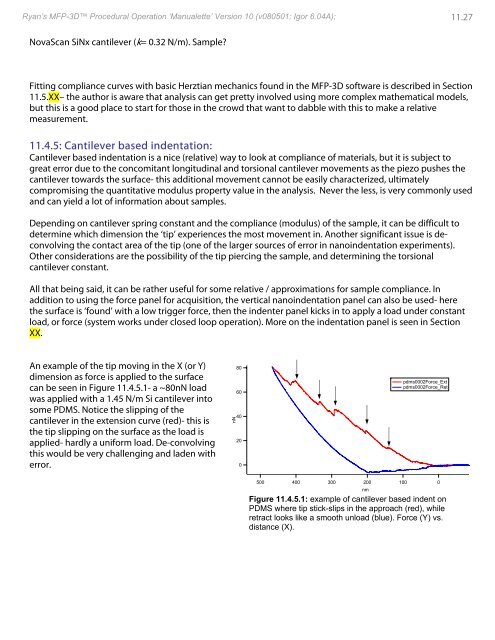
An example of the tip moving in the X (or Y)<br />
dimension as force is applied to the surface<br />
can be seen in Figure 11.4.5.1- a ~80nN load<br />
was applied with a 1.45 N/m Si cantilever into<br />
some PDMS. Notice the slipping of the<br />
cantilever in the extension curve (red)- this is<br />
the tip slipping on the surface as the load is<br />
applied- hardly a uniform load. De-convolving<br />
this would be very challenging and laden with<br />
error.<br />
nN<br />
80<br />
60<br />
40<br />
20<br />
0<br />
pdms0002Force_Ext<br />
pdms0002Force_Ret<br />
500 400 300 200 100 0<br />
nm<br />
Figure 11.4.5.1: example of cantilever based indent on<br />
PDMS where tip stick-slips in the approach (red), while<br />
retract looks like a smooth unload (blue). Force (Y) vs.<br />
distance (X).