B - St. Cloud State University
B - St. Cloud State University
B - St. Cloud State University

Create successful ePaper yourself
Turn your PDF publications into a flip-book with our unique Google optimized e-Paper software.
Ryan’s MFP-3D Procedural Operation ‘Manualette’ Version 10 (v080501; Igor 6.04A); 8.3<br />
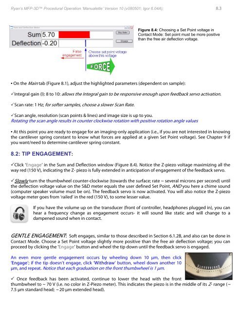
Figure 8.4: Choosing a Set Point voltage in<br />
Contact Mode: Set point must be more positive<br />
than the free air deflection voltage.<br />
▪ On the Main tab (Figure 8.1), adjust the highlighted parameters (dependent on sample):<br />
Integral gain (I): 8 to 10: allows the Integral gain to be responsive enough upon feedback servo activation.<br />
Scan rate: 1 Hz; for softer samples, choose a slower Scan Rate.<br />
Scan angle, resolution (scan points & lines) and image size is up to you.<br />
Rotating the scan angle results in counter clockwise rotation with positive rotation angle values<br />
▪ At this point you are ready to engage for an imaging-only application (i.e., if you are not interested in knowing<br />
the cantilever spring constant to know what forces are applied at a given Set Point voltage). See Chapter 9 if<br />
you want/need to determine cantilever spring constant.<br />
8.2: TIP ENGAGEMENT:<br />
Click ‘Engage’ in the Sum and Deflection window (Figure 8.4). Notice the Z-piezo voltage maximizing all the<br />
way red (150 V), indicating the Z- piezo is fully extended in anticipation of engagement of the feedback servo.<br />
Slowly turn the thumbwheel counter-clockwise (towards the surface; rate ~ several microns per second) until<br />
the deflection voltage value on the S&D meter equals the user defined Set Point, AND you here a chime sound<br />
(computer speaker volume must be on). The feedback servo is now activated. You will also notice the Z-piezo<br />
voltage meter goes from ‘railed’ in the red (150 V), to some lesser value.<br />
If you have the volume up on the transducer (front of controller, headphones plugged in), you can<br />
hear a frequency change as engagement occurs- it will sound like static and will change to a<br />
dampened sound when in contact.<br />
GENTLE ENGAGEMENT: Soft engages, similar to those described in Section 6.1.2B, and also can be done in<br />
Contact Mode. Choose a Set Point voltage slightly more positive than the free air deflection voltage; you can<br />
proceed by clicking the ‘Engage’ button and wheel the tip down until the feedback servo is engaged.<br />
An even more gentle engagement occurs by wheeling down 10 μm, then click<br />
‘Engage’; if the tip doesn’t engage, click ‘Withdraw’ button, wheel down another 10<br />
μm, and repeat. Notice that each graduation on the front thumbwheel is 1 μm.<br />
Once feedback has been activated, continue to lower the head with the front<br />
thumbwheel to ~ 70 V (i.e. no color in Z-Piezo meter). This indicates the piezo is in the middle of its Z- range (~<br />
7.5 μm standard head; ~ 20 μm extended head).