BlueEva+P25/G2/IEEE - Stollmann
BlueEva+P25/G2/IEEE - Stollmann
BlueEva+P25/G2/IEEE - Stollmann

Create successful ePaper yourself
Turn your PDF publications into a flip-book with our unique Google optimized e-Paper software.
<strong>BlueEva+P25</strong>/<strong>G2</strong>/<strong>IEEE</strong><br />
Evaluation Kit User Guide<br />
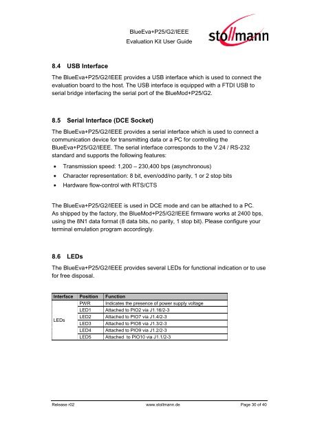
8.4 USB Interface<br />
The <strong>BlueEva+P25</strong>/<strong>G2</strong>/<strong>IEEE</strong> provides a USB interface which is used to connect the<br />
evaluation board to the host. The USB interface is equipped with a FTDI USB to<br />
serial bridge interfacing the serial port of the BlueMod+P25/<strong>G2</strong>.<br />
8.5 Serial Interface (DCE Socket)<br />
The <strong>BlueEva+P25</strong>/<strong>G2</strong>/<strong>IEEE</strong> provides a serial interface which is used to connect a<br />
communication device for transmitting data or a PC for controlling the<br />
<strong>BlueEva+P25</strong>/<strong>G2</strong>/<strong>IEEE</strong>. The serial interface corresponds to the V.24 / RS-232<br />
standard and supports the following features:<br />
Transmission speed: 1,200 – 230,400 bps (asynchronous)<br />
Character representation: 8 bit, even/odd/no parity, 1 or 2 stop bits<br />
Hardware flow-control with RTS/CTS<br />
The <strong>BlueEva+P25</strong>/<strong>G2</strong>/<strong>IEEE</strong> is used in DCE mode and can be attached to a PC.<br />
As shipped by the factory, the BlueMod+P25/<strong>G2</strong>/<strong>IEEE</strong> firmware works at 2400 bps,<br />
using the 8N1 data format (8 data bits, no parity, 1 stop bit). Please configure your<br />
terminal emulation program accordingly.<br />
8.6 LEDs<br />
The <strong>BlueEva+P25</strong>/<strong>G2</strong>/<strong>IEEE</strong> provides several LEDs for functional indication or to use<br />
for free disposal.<br />
Interface Position Function<br />
PWR Indicates the presence of power supply voltage<br />
LED1 Attached to PIO2 via J1.16/2-3<br />
LEDs<br />
LED2 Attached to PIO7 via J1.4/2-3<br />
LED3 Attached to PIO8 via J1.3/2-3<br />
LED4 Attached to PIO9 via J1.2/2-3<br />
LED5 Attached to PIO10 via J1.1/2-3<br />
Release r02 www.stollmann.de Page 30 of 40