BlueEva+P25/G2/IEEE - Stollmann
BlueEva+P25/G2/IEEE - Stollmann
BlueEva+P25/G2/IEEE - Stollmann

Create successful ePaper yourself
Turn your PDF publications into a flip-book with our unique Google optimized e-Paper software.
<strong>BlueEva+P25</strong>/<strong>G2</strong>/<strong>IEEE</strong><br />
Evaluation Kit User Guide<br />
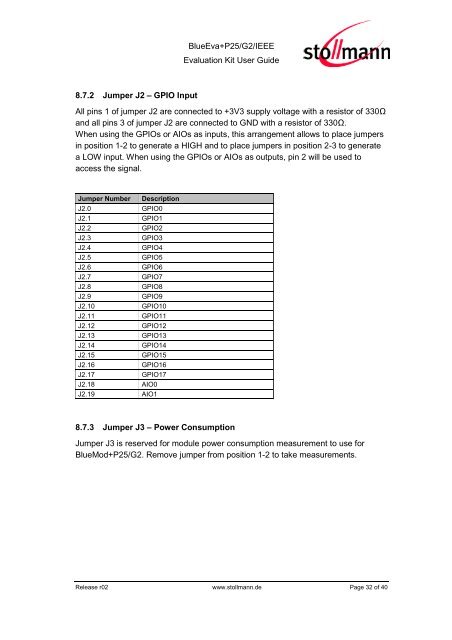
8.7.2 Jumper J2 – GPIO Input<br />
All pins 1 of jumper J2 are connected to +3V3 supply voltage with a resistor of 330Ω<br />
and all pins 3 of jumper J2 are connected to GND with a resistor of 330Ω.<br />
When using the GPIOs or AIOs as inputs, this arrangement allows to place jumpers<br />
in position 1-2 to generate a HIGH and to place jumpers in position 2-3 to generate<br />
a LOW input. When using the GPIOs or AIOs as outputs, pin 2 will be used to<br />
access the signal.<br />
Jumper Number Description<br />
J2.0 GPIO0<br />
J2.1 GPIO1<br />
J2.2 GPIO2<br />
J2.3 GPIO3<br />
J2.4 GPIO4<br />
J2.5 GPIO5<br />
J2.6 GPIO6<br />
J2.7 GPIO7<br />
J2.8 GPIO8<br />
J2.9 GPIO9<br />
J2.10 GPIO10<br />
J2.11 GPIO11<br />
J2.12 GPIO12<br />
J2.13 GPIO13<br />
J2.14 GPIO14<br />
J2.15 GPIO15<br />
J2.16 GPIO16<br />
J2.17 GPIO17<br />
J2.18 AIO0<br />
J2.19 AIO1<br />
8.7.3 Jumper J3 – Power Consumption<br />
Jumper J3 is reserved for module power consumption measurement to use for<br />
BlueMod+P25/<strong>G2</strong>. Remove jumper from position 1-2 to take measurements.<br />
Release r02 www.stollmann.de Page 32 of 40