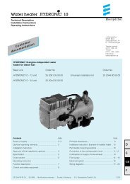
AIRTRONIC D2/D4 Espar
AIRTRONIC D2/D4 Espar
AIRTRONIC D2/D4 Espar

You also want an ePaper? Increase the reach of your titles
YUMPU automatically turns print PDFs into web optimized ePapers that Google loves.
12<br />
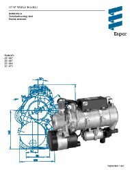
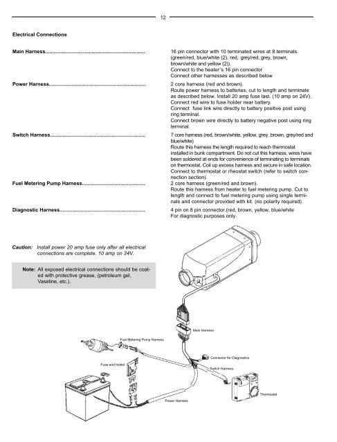
Electrical Connections<br />
Main Harness.......................................................................<br />
Power Harness.....................................................................<br />
Switch Harness....................................................................<br />
Fuel Metering Pump Harness.............................................<br />
Diagnostic Harness.............................................................<br />
16 pin connector with 10 terminated wires at 8 terminals.<br />
(green/red, blue/white (2), red, grey/red, grey, brown,<br />
brown/white and yellow (2)).<br />
Connect to the heater ’s 16 pin connector<br />
Connect other harnesses as described below<br />
2 core harness (red and brown).<br />
Route power harness to batteries, cut to length and terminate<br />
as described below. Install 20 amp fuse last. (10 amp on 24V).<br />
Connect red wire to fuse holder near battery.<br />
Connect fuse link wire directly to battery positive post using<br />
ring terminal.<br />
Connect brown wire directly to battery negative post using ring<br />
terminal.<br />
7 core harness (red, brown/white, yellow, grey, brown, grey/red and<br />
b l u e / w h i t e )<br />
Route this harness the length required to reach thermostat<br />
installed in bunk compartment. Do not cut this harness, wires have<br />
been soldered at ends for convenience of terminating to terminals<br />
on thermostat. Coil up excess harness and secure in safe location.<br />
Connect to thermostat or rheostat switch (refer to switch connection<br />
section).<br />
2 core harness (green/red and brown).<br />
Route this harness from heater to fuel metering pump. Cut to<br />
length and connect to fuel metering pump using single terminals<br />
and connector provided with kit. (no polarity required).<br />
4 pin on 8 pin connector.(red, brown, yellow, blue/white<br />
For diagnostic purposes only.<br />
Caution: Install power 20 amp fuse only after all electrical<br />
connections are complete. 10 amp on 24V.<br />
Note: All exposed electrical connections should be coated<br />
with protective grease, (petroleum gel,<br />
Vaseline, etc.).<br />
Main Harness<br />
Fuel Metering Pump Harness<br />
Connector for Diagnostics<br />
Fuse and holder<br />
Switch Harness<br />
Thermostat<br />
Power Harness