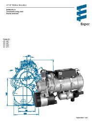
AIRTRONIC D2/D4 Espar
AIRTRONIC D2/D4 Espar
AIRTRONIC D2/D4 Espar

Create successful ePaper yourself
Turn your PDF publications into a flip-book with our unique Google optimized e-Paper software.
26<br />
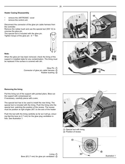
Heater Casing Disassembly<br />
• remove the <strong>AIRTRONIC</strong> cover<br />
• remove the control unit.<br />
Disconnect the connector of the glow pin cable harness from<br />
the controller.<br />
Remove the rubber bush and use the special tool (SW 12) to<br />
unscrew the glow pin.<br />
The special tool is included with the glow pin.<br />
Tighten torque of the glow pin : 6 +0.5 Nm<br />
Note:<br />
When the glow pin has been removed, check the lining of the<br />
support in installed state for any contamination. The lining must<br />
be replaced if the surface is covered with dirt.<br />
Glow Pin<br />
Connector of glow pin cable harness<br />
Rubber bushing<br />
Removing the lining<br />
Pull the lining out of the support with pointed pliers. Blow out<br />
the support with compressed air.<br />
If necessary, carefully pierce with a wire.<br />
The special tool has to be used to install the new lining. The<br />
special tool is included with the lining. Push the lining onto the<br />
special tool, watching the position of the recess. The recess<br />
must be position at right angles (90°) to the axis of the heater<br />
Push the tool with the lining carefully as far as it will go, ensuring<br />
that the bore (ø 2.7 mm) for the glow plug ventilation is<br />
free. See illustration 1<br />
Special tool with lining<br />
Position of recess<br />
Lining<br />
Bore (Ø 2.7 mm) for glow pin ventilation<br />
illustration 1