AIRTRONIC D2/D4 Espar
AIRTRONIC D2/D4 Espar
AIRTRONIC D2/D4 Espar

You also want an ePaper? Increase the reach of your titles
YUMPU automatically turns print PDFs into web optimized ePapers that Google loves.
13<br />
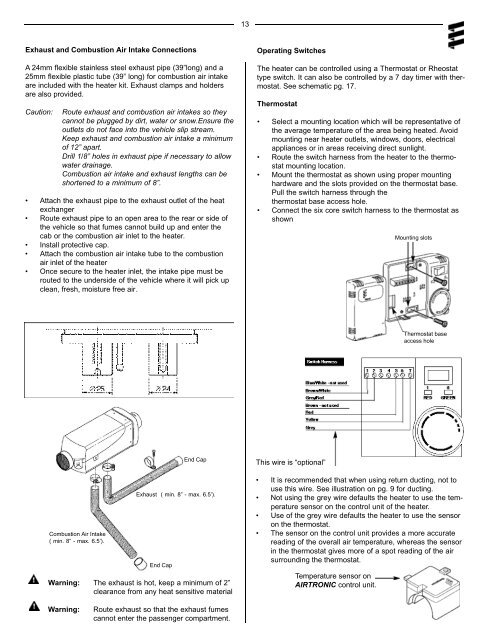
Exhaust and Combustion Air Intake Connections<br />
A 24mm flexible stainless steel exhaust pipe (39”long) and a<br />
25mm flexible plastic tube (39” long) for combustion air intake<br />
are included with the heater kit. Exhaust clamps and holders<br />
are also provided.<br />
Caution:<br />
Route exhaust and combustion air intakes so they<br />
cannot be plugged by dirt, water or snow.Ensure the<br />
outlets do not face into the vehicle slip stream.<br />
Keep exhaust and combustion air intake a minimum<br />
of 12” apart.<br />
Drill 1/8” holes in exhaust pipe if necessary to allow<br />
water drainage.<br />
Combustion air intake and exhaust lengths can be<br />
shortened to a minimum of 8”.<br />
• Attach the exhaust pipe to the exhaust outlet of the heat<br />
exchanger<br />
• Route exhaust pipe to an open area to the rear or side of<br />
the vehicle so that fumes cannot build up and enter the<br />
cab or the combustion air inlet to the heater.<br />
• Install protective cap.<br />
• Attach the combustion air intake tube to the combustion<br />
air inlet of the heater<br />
• Once secure to the heater inlet, the intake pipe must be<br />
routed to the underside of the vehicle where it will pick up<br />
clean, fresh, moisture free air.<br />
Operating Switches<br />
The heater can be controlled using a Thermostat or Rheostat<br />
type switch. It can also be controlled by a 7 day timer with thermostat.<br />
See schematic pg. 17.<br />
Thermostat<br />
• Select a mounting location which will be representative of<br />
the average temperature of the area being heated. Avoid<br />
mounting near heater outlets, windows, doors, electrical<br />
appliances or in areas receiving direct sunlight.<br />
• Route the switch harness from the heater to the thermostat<br />
mounting location.<br />
• Mount the thermostat as shown using proper mounting<br />
hardware and the slots provided on the thermostat base.<br />
Pull the switch harness through the<br />
thermostat base access hole.<br />
• Connect the six core switch harness to the thermostat as<br />
shown<br />
Mounting slots<br />
Thermostat base<br />
access hole<br />
Combustion Air Intake<br />
( min. 8” - max. 6.5’).<br />
Exhaust ( min. 8” - max. 6.5’).<br />
End Cap<br />
End Cap<br />
Warning: The exhaust is hot, keep a minimum of 2”<br />
clearance from any heat sensitive material<br />
This wire is “optional”<br />
• It is recommended that when using return ducting, not to<br />
use this wire. See illustration on pg. 9 for ducting.<br />
• Not using the grey wire defaults the heater to use the temperature<br />
sensor on the control unit of the heater.<br />
• Use of the grey wire defaults the heater to use the sensor<br />
on the thermostat.<br />
• The sensor on the control unit provides a more accurate<br />
reading of the overall air temperature, whereas the sensor<br />
in the thermostat gives more of a spot reading of the air<br />
surrounding the thermostat.<br />
Temperature sensor on<br />
<strong>AIRTRONIC</strong> control unit.<br />
Warning:<br />
Route exhaust so that the exhaust fumes<br />
cannot enter the passenger compartment.