AIRTRONIC D2/D4 Espar
AIRTRONIC D2/D4 Espar
AIRTRONIC D2/D4 Espar

You also want an ePaper? Increase the reach of your titles
YUMPU automatically turns print PDFs into web optimized ePapers that Google loves.
20<br />
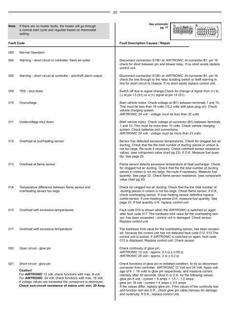
Note:<br />
If there are no heater faults, the heater will go through<br />
a normal start cycle and regulate based on thermostat<br />
setting.<br />
See schematic<br />
pg. 17<br />
Fault Code<br />
Fault Description Causes / Repair<br />
000 Normal Operation<br />
004 Warning - short circuit in controller, fresh air-outlet Disconnect connection S1/B1 at <strong>AIRTRONIC</strong>. At connector B1, pin 16<br />
check for short between pin and blower relay. If no short exists replace<br />
control unit.<br />
005 Warning - short circuit at controller - anti-theft alarm output Disconnect connection S1/B1 at <strong>AIRTRONIC</strong>. At connector B1, pin 16<br />
check the line through to the relay isolating switch or theft warning in<br />
line for short circuit to chassis. If no short exists replace control unit.<br />
009 TRS - shut down Switch off due to signal change.Check for change of signal from (+) to<br />
(-) at pin 13 (S1) or a (+) signal at pin 14 (S1).<br />
010 Overvoltage Start vehicle motor. Check voltage at (B1) between terminals 1 and 10.<br />
This must be less than 16 volts (15.2 volts with glow plug on). Check<br />
vehicle charging system.<br />
<strong>AIRTRONIC</strong> 24 volt - voltage must be less than 32 volts<br />
011 Undervoltage shut down Start vehicle motor. Check voltage at connector (B1) between terminals<br />
1 and 10. This must be more than 10 volts. Check vehicle charging<br />
system. Check batteries and connections.<br />
<strong>AIRTRONIC</strong> 24 volt - voltage must be more than 21 volts.<br />
012 Overheat at overheating sensor Sensor has detected excessive temperatures. Check for clogged hot air<br />
ducting. Check that the the total number of ducting pieces in unison is<br />
not too large. Re-route if necessary. Check overheat sensor resistance<br />
values. (see component value chart pg 23). If O.K. Measure fuel quantity.<br />
See page 23.<br />
013 Overheat at flame sensor Flame sensor detects excessive temperature at heat exchanger. Check<br />
for clogged hot air ducting. Check that the the total number of ducting<br />
pieces in unison is not too large. Re-route if necessary. Measure fuel<br />
quantity. See page 22. Check flame sensor resistance. (see component<br />
value chart pg 22)<br />
014 Temperature difference between flame sensor and Check for clogged hot air ducting. Check that the the total number of<br />
overheating sensor too large<br />
ducting pieces in unison is not too large. Check flame sensor, if O.K.,<br />
check overheating sensor. If over-heating sensor defective replace<br />
combi-sensor. If over-heating sensor O.K. measure fuel quantity. See<br />
page 23. If fuel quantity O.K. replace control unit.<br />
015 Overheat with excessive temperatures Fault code 015 is shown when the <strong>AIRTRONIC</strong> is switched on again<br />
after fault code 017. The hardware limit value for the overheating sensor,<br />
has been exceeded - control unit is damaged. Check sensor.<br />
Replace control unit.<br />
017 Overheat with excessive temperature The hardware limit value for the overheating sensor, has been exceeded,<br />
because the control unit has not detected fault code 012, 013.The<br />
control unit is locked. If <strong>AIRTRONIC</strong> is switched on again, fault code<br />
015 is displayed. Replace control unit. Check sensor.<br />
020 Open circuit - glow pin Check continuity of glow pin.<br />
<strong>AIRTRONIC</strong> 12 volt - approx. 0.5 Ω ± 0.05 Ω<br />
<strong>AIRTRONIC</strong> 24 volt - approx. 2 Ω ± 0.2 Ω<br />
021 Short circuit - glow pin<br />
Caution!<br />
Check functions of glow pin in installed condition, to do so disconnect<br />
connector from controller. <strong>AIRTRONIC</strong> 12 Volt and 24 Volt. Apply voltage<br />
of 8 / 18 volts to glow pin respectively, and measure current<br />
For <strong>AIRTRONIC</strong> 12 volt, check functions with max. 8 volt<br />
intensity after 40 seconds. Glow in is O.K. for the following values:<br />
For <strong>AIRTRONIC</strong> 24 volt, check functions with max. 18 volt.<br />
glow pin 8 volt - current = 9 amps + 1.5 / - 1.2 amps<br />
if voltage values are exceeded the component is destroyed.<br />
glow pin 18 volt - current = 4 amps ± 0.5 amps<br />
Check sort-circuit resistance of mains unit: min. 20 Amp. If the values differ, replace glow pin. If the values of the continuity test<br />
and function test are O.K., check glow pin cable harness for damage<br />
and continuity. If O.K., replace control unit.