CHANGE SERVICE REQUESTED The California Surveyor ... - CLSA
CHANGE SERVICE REQUESTED The California Surveyor ... - CLSA
CHANGE SERVICE REQUESTED The California Surveyor ... - CLSA

Create successful ePaper yourself
Turn your PDF publications into a flip-book with our unique Google optimized e-Paper software.
By: Jas Arnold, PLS, CP<br />
Controlling a Photogrammetric Model<br />
from the Sky<br />
Background<br />
Conventional photogrammetric methods for model setup<br />
utilize the known positions of paneled control points on<br />
the ground and the measurement of these control points<br />
within the photogrammetric model. <strong>The</strong> re-creation of the<br />
photo geometry that existed when the photographs are<br />
taken (relative orientation) is mixed with these photo control<br />
point measurements (absolute orientation) to produce a<br />
stereo model within the ground coordinate system. If only<br />
the two positions of the camera are known as determined<br />
through airborne GPS observations (AbGPS), the orientation<br />
of the model cannot be accurately determined due to instability<br />
about the flightline. By adding a second flightline perpendicular<br />
to the first, four virtual control points (the camera<br />
centers) coupled with aerotriangulation (AT) can be used to<br />
orient the models. This article will discuss a test performed<br />
to evaluate the feasibility of using control points in the sky to<br />
control a pair of photogrammetric models.<br />
<strong>The</strong> Project<br />
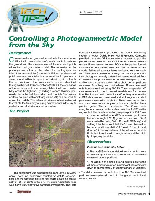
This experiment was conducted on a shoestring. Skyview<br />
Aerial Photo, Inc. generously donated the AbGPS observations<br />
and the additional flightline required to create the control<br />
network of four points in the sky. Two single model flight lines<br />
were flown 3600’ above five paneled control points. <strong>The</strong> Plate<br />
30<br />
Borrego Test Site<br />
Boundary Observatory “provided” the ground monitoring<br />
through a nearby CORS, P486. Rick Engineering Company<br />
provided the static GPS observations required to put the<br />
ground control points and the CORS on the same coordinate<br />
system. Photo centers, denoted PC4X in the graphic, formed<br />
a diamond of “sky control” which was used to control the two<br />
models. Estimated accuracy levels are based on a comparison<br />
of the “true” coordinates of the ground control points with<br />
their photogrammetrically determined values obtained from<br />
AT where all five points serve as unconstrained pass points.<br />
Additionally, the camera station (a.k.a. photo center) positions<br />
determined from the ground control-based AT were compared<br />
with those determined using AbGPS. Three independent AT<br />
runs were made in order to create three data sets for comparison.<br />
<strong>The</strong> first run used conventional AT techniques where the<br />
AbGPS data was not considered and all five-ground control<br />
points were measured in the photos. <strong>The</strong>se points served both<br />
as control points as well as pass points which tie the photographs<br />
together. <strong>The</strong> next run denoted “Set 1” was made<br />
using the four camera positions determined by AbGPS as the<br />
only control. <strong>The</strong> panels served only as pass points. Set 2 was<br />
constrained to the four AbGPS-determined photo centers<br />
and a single (HV-11) ground control point. Set 3<br />
was created by taking Set 1 AT run (AbGPS-only) and<br />
shifting it by the amount that HV-11 was observed to<br />
be out of position (a shift of 3.2’ east, 2.2’ south, and<br />
down 4.6’). <strong>The</strong> consistency of the values in the table<br />
illustrate this systematic misregistration and the validity<br />
of applying the shifts.<br />
Observations<br />
It can be seen in the table below:<br />
• <strong>The</strong> AbGPS-only run yielded results which were<br />
approximately 3’ west and 3’ north, and 4’ above the<br />
measured ground positions.<br />
• <strong>The</strong> addition of a single ground control point to the<br />
AT measurements resulted in positional improvements<br />
down to approximately 1’ horizontally and 2’ vertically.<br />
• <strong>The</strong> shifts between the control and the AbGPS-determined<br />
positions were systematic for both the ground control and<br />
camera centers.<br />
Continued on page 32<br />
www.californiasurveyors.org