CHANGE SERVICE REQUESTED The California Surveyor ... - CLSA
CHANGE SERVICE REQUESTED The California Surveyor ... - CLSA
CHANGE SERVICE REQUESTED The California Surveyor ... - CLSA

Create successful ePaper yourself
Turn your PDF publications into a flip-book with our unique Google optimized e-Paper software.
Continued from page 30<br />
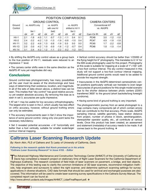
• By shifting the AbGPS-only control values as a group back<br />
to the true position of HV-11, residuals were reduced to an<br />
impressive 1’ level.<br />
• <strong>The</strong> camera center shifts were in the same direction as the<br />
AbGPS AT runs yet magnitudes did vary.<br />
Conclusions<br />
Ground control-less photogrammetry has many possibilities<br />
yet the user must be aware of the shortcomings and have<br />
ways of determining their existence, location, and magnitude.<br />
In all of the sets of data shown above, a distinct bias can be<br />
seen. This implies that “sky control” has good relative accuracy<br />
yet weaker absolute accuracy. By removing this bias as is<br />
seen in set 3, accuracies are quite impressive.<br />
• AT set 1 may be usable for low accuracy orthophotography.<br />
<strong>The</strong> largest error is seen in the Z, which usually has less effect<br />
on ortho accuracy, however, without ground truthing errors<br />
can only be estimated.<br />
• <strong>The</strong> accuracy improvements seen in Set 2 show the importance<br />
of some ground control. Using only one point lacks the<br />
necessary redundancy.<br />
• Set 3 revealed potential accuracies +/-6’ horizontally and<br />
better than a foot vertically, suitable for smaller scale/larger<br />
contour interval mapping.<br />
• Vertical control accuracy should be better than 1/25000 of<br />
the flying height for 6” photography. This translates to 0.14’ for<br />
the 600-scale photography used for this project. Photography<br />
at this scale is suitable for mapping at a scale of 1”=100’ with<br />
a two-foot contour interval. <strong>The</strong> sky control measured in this<br />
study will not support a two-foot contour interval mapping.<br />
Additional ground control points would need to be added to<br />
provide the required strength.<br />
• Inaccuracies in the AbGPS-determined camera/photo center<br />
positions (particularly vertical) can translate to even larger<br />
inaccuracies of ground positions for this single model scenario<br />
due to the shorter distance between photo centers (2200’)<br />
transferred 3600’ to the ground (short backsite/long foresight<br />
syndrome).<br />
• Having some kind of ground truthing is very important.<br />
<strong>The</strong> photogrammetric journey from an aerial photograph to a<br />
map contains many components (all of which contain errors)<br />
that can contribute to the final accuracy. Photo scale, AbGPS<br />
sampling interval, satellite geometry, base station distance<br />
from project, number of photos in block, aerotriangulation,<br />
stereoplotter operator quality, etc., all contribute at various<br />
levels. Once this product has been created, an assessment<br />
and statement (metadata) of accuracy needs to be made. It all<br />
comes back to the ground truthing. ❖<br />
Caltrans Laser Scanning Research Update<br />
By: Kevin Akin, PLS of Caltrans and Ty Lasky of University of <strong>California</strong>, Davis<br />
Following is the research update that Kevin promised us in his article<br />
“Caltrans Laser Scanning Research” in Issue #153. - Editor<br />
<strong>The</strong> Advanced Highway Maintenance and Construction Technology Center (AHMCT) of the University of <strong>California</strong> at<br />
Davis has completed a research project on stationary time of flight Laser Scanners for the <strong>California</strong> Department of<br />
Highways (Caltrans). <strong>The</strong> research consisted of field trials of laser scanners on pavement, a bridge, and test objects.<br />
<strong>The</strong> objective of this testing was to clarify the common limitations of 3D laser scanners, recommend mitigation methods,<br />
help engineers and surveyors to select the right scanner, and determine optimum scanning settings for survey<br />
applications in diverse situations. CAD data formats that should be used for archival and exchanged purposes are also<br />
covered. This information will be used to create laser scanning survey specifications in the Caltrans Survey Manual. <strong>The</strong><br />
completed report can be found at:<br />
http://www.ahmct.ucdavis.edu/images/AHMCT_LidarFinalReport.pdf. ❖<br />
32<br />
www.californiasurveyors.org