susref - Construction IT research at VTT
susref - Construction IT research at VTT
susref - Construction IT research at VTT

Create successful ePaper yourself
Turn your PDF publications into a flip-book with our unique Google optimized e-Paper software.
SUSREF<br />
Sustainable Refurbishment of Building<br />
Facades and External Walls<br />
1 (1)<br />
7th framework programme<br />
Theme Environment (including clim<strong>at</strong>e change)<br />
Small or medium scale <strong>research</strong> project<br />
Grant Agreement no. 226858<br />
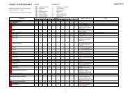
DELIVERABLE 4.2 – GENERAL<br />
REFURBISHMENT CONCPETS<br />
ASSESSMENT RESULTS
SUSREF<br />
Sustainable Refurbishment of Building<br />
Facades and External Walls<br />
7th framework programme<br />
Theme Environment (including clim<strong>at</strong>e change)<br />
Small or medium scale <strong>research</strong> project<br />
Grant Agreement no. 226858<br />
D<strong>at</strong>e:2012-4-30<br />
Version: Final<br />
1 (57)<br />
Deliverable:<br />
D4.2 - General refurbishment concepts<br />
Introduction, Background, Description of refurbishment concepts and Aspects of<br />
assessment<br />
Authors: Antti Ruuska, Sirje Vares, Tarja Häkkinen<br />
List of contents:<br />
1. Introduction ........................................................................................................................... 1<br />
2. Objectives ............................................................................................................................. 2<br />
3. Background - refurbishment technologies - liter<strong>at</strong>ure review ................................................. 5<br />
3.1 Introduction .................................................................................................................... 5<br />
3.2 Classific<strong>at</strong>ion of refurbishment technologies .................................................................. 5<br />
3.2.1 Role of insul<strong>at</strong>ion m<strong>at</strong>erials ........................................................................................ 6<br />
3.3 Technologies for replacing existing walls ....................................................................... 8<br />
3.4 Technologies for applying external thermal insul<strong>at</strong>ion layers ......................................... 8<br />
3.4.1 Thermal bridges in external thermal insul<strong>at</strong>ion ........................................................... 8<br />
3.4.2 Air tightness in external thermal insul<strong>at</strong>ion ................................................................. 9<br />
3.4.3 Different concepts for applying external thermal insul<strong>at</strong>ion layers ............................ 10<br />
3.4.3.1 External thermal insul<strong>at</strong>ion composite systems (ETICS) .................................. 10<br />
3.4.3.2 Ventil<strong>at</strong>ed façades............................................................................................ 11<br />
3.4.3.3 External thermal insul<strong>at</strong>ion panel systems ....................................................... 12<br />
3.4.3.4 Insul<strong>at</strong>ing plasters ............................................................................................ 13<br />
3.5 Internal thermal insul<strong>at</strong>ion of the envelope ................................................................... 15<br />
3.5.1 Risk of condens<strong>at</strong>ion................................................................................................ 15<br />
3.5.2 Thermal bridges and air tightness in internal thermal insul<strong>at</strong>ion ............................... 15<br />
3.5.3 Different concepts for applying internal thermal insul<strong>at</strong>ion ....................................... 16<br />
3.5.3.1 Plasterdboard lamin<strong>at</strong>es................................................................................... 17<br />
3.5.3.2 Insul<strong>at</strong>ion boards covered with plasterboard .................................................... 17<br />
3.5.3.3 Insul<strong>at</strong>ion boards fixed to wall and plastered directly ........................................ 18<br />
3.5.3.4 Insul<strong>at</strong>ion fixed to a freestanding studwork ....................................................... 18<br />
3.6 Cavity insul<strong>at</strong>ion .......................................................................................................... 19<br />
3.6.1 Thermal bridges and humidity .................................................................................. 20<br />
3.6.2 Insul<strong>at</strong>ing with bulk m<strong>at</strong>erial ..................................................................................... 21
SUSREF<br />
2 (57)<br />
3.6.3 Insul<strong>at</strong>ing with foam ................................................................................................. 22<br />
3.7 Combined wall insul<strong>at</strong>ions ........................................................................................... 22<br />
3.7.1 Internal insul<strong>at</strong>ion + External insul<strong>at</strong>ion .................................................................... 22<br />
3.7.2 Internal insul<strong>at</strong>ion + Cavity insul<strong>at</strong>ion ....................................................................... 23<br />
3.7.3 External insul<strong>at</strong>ion + Cavity insul<strong>at</strong>ion ...................................................................... 23<br />
3.8 Advanced refurbishment technologies ......................................................................... 23<br />
3.8.1 Phase-changing m<strong>at</strong>erials (PCM’s) .......................................................................... 23<br />
3.8.1.1 Example uses of PCM’s - Gypsum plasterboards with microencapsul<strong>at</strong>ed<br />
paraffin 24<br />
3.8.1.2 Example uses of PCM’s - Plaster with microencapsul<strong>at</strong>ed paraffin .................. 24<br />
3.8.1.3 Example uses of PCM’s – Concrete or concrete blocks with microencapsul<strong>at</strong>ed<br />
paraffin 25<br />
3.8.1.4 Example uses of PCM’s -Translucent wall elements ........................................ 25<br />
3.8.2 Vacuum-insul<strong>at</strong>ion panels ........................................................................................ 26<br />
3.8.3 Green walls .............................................................................................................. 27<br />
3.8.3.1 Spots green suspended walls .......................................................................... 27<br />
3.8.3.2 Compact green suspended wall system ........................................................... 28<br />
3.8.3.3 Living walls system .......................................................................................... 28<br />
3.8.3.4 Clim<strong>at</strong>ic skin layer ............................................................................................ 29<br />
3.8.4 Evapor<strong>at</strong>ive wall....................................................................................................... 30<br />
3.8.4.1 An example of an evapor<strong>at</strong>ive wall ................................................................... 30<br />
3.8.5 Photovoltaic façades ................................................................................................ 31<br />
3.8.5.1 Ventil<strong>at</strong>ed photovoltaic façades ........................................................................ 32<br />
3.8.6 Pre-he<strong>at</strong>ing hot w<strong>at</strong>er with solar collectors ............................................................... 33<br />
3.8.6.1 Pre-he<strong>at</strong>ing of hot w<strong>at</strong>er –façade integr<strong>at</strong>ed vacuum tube collectors ................ 34<br />
3.8.6.2 Pre-he<strong>at</strong>ing of hot w<strong>at</strong>er –façade integr<strong>at</strong>ed collector pl<strong>at</strong>es ............................ 35<br />
3.8.6.3 Pre-he<strong>at</strong>ing of hot w<strong>at</strong>er –façade integr<strong>at</strong>ed collector system........................... 36<br />
3.8.7 Transparent insul<strong>at</strong>ion (TI) m<strong>at</strong>erials ........................................................................ 36<br />
3.8.7.1 Applic<strong>at</strong>ions of TI insul<strong>at</strong>ion -Solar wall he<strong>at</strong>ing with TI .................................... 38<br />
3.8.7.2 Applic<strong>at</strong>ions of TI insul<strong>at</strong>ion –Elimin<strong>at</strong>ing thermal bridges with TI ..................... 40<br />
3.8.8 Winter he<strong>at</strong>ing and summer cooling by glass façade (trombe wall) .......................... 40<br />
3.8.9 Solar chimney façades............................................................................................. 41<br />
4. Description of the refurbishment concepts ........................................................................... 43<br />
4.1 External insul<strong>at</strong>ion ....................................................................................................... 44<br />
4.2 Internal insul<strong>at</strong>ion ........................................................................................................ 47<br />
4.3 Cavity insul<strong>at</strong>ion .......................................................................................................... 49<br />
4.4 Replacing refurbishment .............................................................................................. 51<br />
5. References .......................................................................................................................... 54
SUSREF<br />
1 (57)<br />
1. Introduction<br />
This report belongs to the Task 4.1. of the Sustainable Refurbishment SUSREF project.<br />
The report describes exterior wall refurbishment technologies, describes the refurbishment<br />
concepts developed by the projects and presents the assessment results of the concepts. In<br />
addition, the report also presents an overview of refurbishment technologies based on<br />
liter<strong>at</strong>ure review.<br />
The main aim of WP 4 is the development and description of product concepts for sustainable<br />
refurbishment of external walls; and also to cre<strong>at</strong>e results for specific targets of partners.<br />
The main questions to tackle include:<br />
To wh<strong>at</strong> extent it is economical and ecological to improve the insul<strong>at</strong>ion capacity of the<br />
building envelope when refurbishing the existing buildings. Especially the issue arises<br />
when estim<strong>at</strong>ing the life-span th<strong>at</strong> can be achieved with different technologies. In each<br />
case we should be able to optimize the total energy consumption during the life-span<br />
taking into account the bound energy in the install<strong>at</strong>ion phase and the energy<br />
consumption during the life-span. So far no d<strong>at</strong>a exists to be able to make a reliable<br />
evalu<strong>at</strong>ion.<br />
Improving the insul<strong>at</strong>ion capacity and the air-tightness of the building envelope reflects<br />
the indoor air quality. Wh<strong>at</strong> are these reflections and how to balance and optimize<br />
these with the mechanical systems (he<strong>at</strong>ing, air-conditioning, ventil<strong>at</strong>ion…) so th<strong>at</strong><br />
optimal indoor-air quality can be reached with the optimal ecological impact?<br />
How to maximize the use of external energy sources by using intelligent envelope<br />
structures in refurbishment projects: how to optimize the energy absorption to the<br />
building envelope. The present U-value calcul<strong>at</strong>ions do not take into account the<br />
external energy sources as means of reducing the need for he<strong>at</strong>ing. How can we in<br />
refurbishment projects reduce the he<strong>at</strong> absorption during the warm season to the<br />
building envelope thus reducing the need for air-conditioning? Or would it be better in<br />
some cases to maximize the he<strong>at</strong> absorption and store it in the massive structures. Or<br />
would it be possible to use the absorbed energy as an energy source for he<strong>at</strong>ing and<br />
during the warm season for air-conditioning.<br />
All the above mentioned aspects need to be studied in various clim<strong>at</strong>e conditions.<br />
The product concept development makes use of the systemized approach developed in WP 2<br />
and 3 and 5 and the recommended and developed models of assessment. The description of<br />
the above mentioned aspects is based on the previous WPs, in particular to the deliverable<br />
2.1.
SUSREF<br />
2 (57)<br />
2. Objectives<br />
The main target of SUSREF Deliverable 4.2 is<br />
1. to describe reference concepts for sustainable refurbishment of facades and external<br />
walls<br />
2. to assess these concepts in terms of performance aspects of external walls<br />
The report describes the generic concepts for the refurbishment of external walls and presents<br />
the assessment results of the concepts. The concepts are assessed from the view point of<br />
1. Durability (focus on moisture),<br />
2. Need for care and maintenance<br />
3. Indoor air quality, acoustics + thermal comfort<br />
4. Impact on energy demand for he<strong>at</strong>ing<br />
5. Impact on energy demand for cooling<br />
6. Impact on renewable energy use potential (use of solar panels etc.)<br />
7. Environmental impact of manufacture and maintenance<br />
8. Life cycle costs<br />
9. Aesthetic quality<br />
10. Effect on cultural heritage<br />
11. Structural stability<br />
12. Fire safety<br />
13. Buildability<br />
14. Disturbance to the tenants and to the site<br />
15. Impact on daylight<br />
The report covers the following refurbishment cases<br />
1. External insul<strong>at</strong>ion<br />
2. Internal insul<strong>at</strong>ion<br />
3. Cavity wall insul<strong>at</strong>ion
SUSREF<br />
3 (57)<br />
4. Replacing renov<strong>at</strong>ion<br />
The following buildings types are covered in the development and assessment of the generic<br />
concepts:<br />
A. Small houses<br />
B. Terraced houses<br />
C. Multi-storey<br />
In the assessment of the refurbishment concepts the following clim<strong>at</strong>ic zones are considered<br />
1) Cfb<br />
2) Cfbw<br />
3) Csa<br />
4) Dfb<br />
5) Dfc<br />
However, in some cases a less number of clim<strong>at</strong>ic conditions are considered.<br />
The original wall types considered in the assessment of the generic refurbishment concepts<br />
are as follows:<br />
Wall type<br />
Relevant in<br />
clim<strong>at</strong>ic zones<br />
Relevant in<br />
building types ?<br />
Solid wall (brick, n<strong>at</strong>ural<br />
stone)<br />
Sandwich element (concrete<br />
panel + concrete panel)<br />
Load bearing wood structure<br />
(wooden frame)<br />
Load bearing cavity without<br />
insul<strong>at</strong>ion (brick + concrete<br />
block)<br />
Insul<strong>at</strong>ed load bearing cavity<br />
(concrete block + concrete<br />
block)<br />
1, 2 A<br />
2, 3 C<br />
2, 3 A, B, C<br />
2 A, B, C<br />
2 A, B, C
SUSREF<br />
4 (57)<br />
Non-load bearing cavity<br />
(hollow brick + perfor<strong>at</strong>ed<br />
brick)<br />
Non-load bearing concrete<br />
block without insul<strong>at</strong>ion<br />
(hollow brick + concrete<br />
block)<br />
1 A, C<br />
1 A, C<br />
The generic concepts are assessed analytically and when relevant with help of parametric<br />
approach. The parametric approach means th<strong>at</strong> with regard to each performance aspect<br />
the generic concepts will assessed by dealing with relevant issues as parameters.<br />
Relevant issues are different for different performance aspects. Relevant issues may be<br />
for example<br />
• Quality and performance properties of m<strong>at</strong>erials<br />
• Thickness of insul<strong>at</strong>ion and other layers<br />
• Existence of air cavity<br />
• Fixing mechanisms<br />
• Quality of surface m<strong>at</strong>erial<br />
• Condition of the existing structure<br />
• Rainfalls and temper<strong>at</strong>ures
SUSREF<br />
5 (57)<br />
3. Background - refurbishment technologies - liter<strong>at</strong>ure review<br />
3.1 Introduction<br />
This study focuses on additional thermal insul<strong>at</strong>ion of external walls. In other words, this study<br />
leaves out all the other building components and systems. The main goal of this study is to<br />
give a comprehensive view of the different technologies available for refurbishing external<br />
walls.<br />
The scope of this study is on residential buildings, but the results and technologies presented<br />
here may also be applied to other building types.<br />
3.2 Classific<strong>at</strong>ion of refurbishment technologies<br />
This study divides the different refurbishment technologies under five main technologies. The<br />
technologies differ from each other mainly by the placement of new insul<strong>at</strong>ion layers. SUSREF<br />
2.1 presents a brief explan<strong>at</strong>ion of each of these technologies and this study will discuss them<br />
in more detail.<br />
The primary technologies for refurbishing external wall, as in SUSREF 2.1, are:<br />
Technologies for replacing existing walls<br />
Technologies for applying external (insul<strong>at</strong>ion) layers<br />
Technologies for inserting (insul<strong>at</strong>ion) m<strong>at</strong>erials in cavities in existing walls<br />
Technologies for applying internal insul<strong>at</strong>ion<br />
Other (advanced) refurbishment technologies<br />
This classific<strong>at</strong>ion has been justified earlier (SUSREF 2.1) by the significance of the insul<strong>at</strong>ion<br />
for the moisture and temper<strong>at</strong>ure balance of a wall structure. Each of the technologies have<br />
some advantages and disadvantages, some of which are listed in Table 1.
SUSREF<br />
6 (57)<br />
Table 1, Different placements for thermal insul<strong>at</strong>ion. Modified from IEA (2010).<br />
3.2.1 Role of insul<strong>at</strong>ion m<strong>at</strong>erials<br />
Regardless of the selected technology, a number of insul<strong>at</strong>ion m<strong>at</strong>erials exists th<strong>at</strong> can be<br />
used with each of the technologies. The selection of the m<strong>at</strong>erial depends on various factors<br />
and the optimal solution is often project-specific, depending on the individual characteristics of<br />
a refurbishment project, such as economic constraints.<br />
However, the sustainability consider<strong>at</strong>ions in m<strong>at</strong>erial selection should aim to finding the<br />
optimal m<strong>at</strong>erial, based on energy performance, environment and human health (IEA 2010).<br />
The following Table 2 lists some of the most common insul<strong>at</strong>ion m<strong>at</strong>erials and their main<br />
characteristics.
SUSREF<br />
7 (57)<br />
Table 2. Characteristics of some insul<strong>at</strong>ion m<strong>at</strong>erials. As in IEA 2010 (multiple d<strong>at</strong>a sources).
SUSREF<br />
8 (57)<br />
3.3 Technologies for replacing existing walls<br />
Technologies for replacing existing walls or parts of them are large-scale renov<strong>at</strong>ions. If the<br />
walls to be replaced are non-load-bearing, they may be completely replaced in some cases.<br />
Especially curtain walls of high-rise buildings, or parts of walls in residential blocks of fl<strong>at</strong>s may<br />
be suitable for complete replacement. (SUSREF 2.1)<br />
In the case of load-bearing walls, only the existing façade and insul<strong>at</strong>ion layer are usually<br />
removed and the inner load-bearing layer is left in place.<br />
Replacing refurbishment technologies may be the only means of refurbishment if insul<strong>at</strong>ion<br />
layer has excessive microbe growth or the façade or its anchoring has massive structural<br />
damage. Replacing technologies may also be used if an especially long service life is wanted<br />
or if the wall would become too thick with additional external thermal insul<strong>at</strong>ion. Replacement<br />
also enables hidden damages to be fixed. (Haukijärvi 2006)<br />
Replacing refurbishment technologies give a lot of freedom in selection of the new wall<br />
structure. If non-load-bearing walls of a building are completely removed, the new wall<br />
structure can be chosen freely. In case of load-bearing walls, all the methods presented in the<br />
section “technologies for applying external thermal insul<strong>at</strong>ion layers” can be used for new<br />
external layer, once the existing façade and insul<strong>at</strong>ion are removed.<br />
3.4 Technologies for applying external thermal insul<strong>at</strong>ion layers<br />
External insul<strong>at</strong>ion is usually the preferred method for adding insul<strong>at</strong>ion to existing buildings. It<br />
does not cause loss of interior space and it may be possible to install while the building is in<br />
use. It also makes it possible to address thermal bridges and moisture problems in a<br />
comprehensive way. (SUSREF D2.1)<br />
Additional external insul<strong>at</strong>ion can have a significant impact on mitig<strong>at</strong>ing the thermal losses of<br />
a wall, diminishing the effects of existing thermal bridges and improving the air tightness of a<br />
wall. (Groleau et al. 2007)<br />
The additional insul<strong>at</strong>ion and new cladding are usually fixed straight to the load-bearing<br />
system of the existing walls, but some degree of removal of external construction, e.g.<br />
external siding, may also be needed. (SUSREF D2.1)<br />
However, in some cases, the external thermal insul<strong>at</strong>ion might be hard to implement, since it<br />
alters the visual appearance of the building. This might be the case especially on the “street<br />
side”-facades of buildings in urban areas (IEA 2010) or in historical buildings. External thermal<br />
insul<strong>at</strong>ion causes also challenges, since eaves, verges and details around windows often<br />
need to be altered. (EST 2005)<br />
3.4.1 Thermal bridges in external thermal insul<strong>at</strong>ion<br />
External thermal insul<strong>at</strong>ion can guarantee the continuity of the insul<strong>at</strong>ion and reduce the<br />
number of thermal bridges in the external wall. (IEA 2010) However, removing all the thermal<br />
bridges during a renov<strong>at</strong>ion can be a complic<strong>at</strong>ed and laborious task. The following figure<br />
shows some typical thermal bridge problems for external thermal insul<strong>at</strong>ion and possible<br />
corrective measures for each of the problems. (IEA 2010)
SUSREF<br />
9 (57)<br />
Image 1. Thremal bridge problems for external thermal insualtion and their possible solutions<br />
(IEA 2010)<br />
3.4.2 Air tightness in external thermal insul<strong>at</strong>ion<br />
Poor air tightness of external wall causes unwanted air infiltr<strong>at</strong>ion through the walls, which<br />
increases energy losses and can cre<strong>at</strong>e a risk of condens<strong>at</strong>ion inside the wall.<br />
One typical source for air leakage is the connections between the external wall and windows<br />
and doors. These connections can be re-sealed when installing external insul<strong>at</strong>ion. Other<br />
sources of unwanted air-leakage are cracks and fissures in the enclosing surfaces and porous<br />
m<strong>at</strong>erials used in walls. (IEA 2010)<br />
Porous m<strong>at</strong>erials, such as bricks, concrete, or mineral wool, which are permeable to air are<br />
often used in wall structures. If these m<strong>at</strong>erials are not protected with an airtight layer, such as<br />
co<strong>at</strong>ed plasterboard, or paint, then the air can flow through the structures causing thermal<br />
losses. (IEA 2010)
SUSREF<br />
10 (57)<br />
3.4.3 Different concepts for applying external thermal insul<strong>at</strong>ion layers<br />
External thermal insul<strong>at</strong>ion means thermal insul<strong>at</strong>ion, which is installed on the outer surface of<br />
an external wall. These systems can be implemented in most cases directly on top of the<br />
existing structure. However, in some cases it might be necessary to remove the cladding and<br />
existing thermal insul<strong>at</strong>ion before applying.<br />
This study divides the external thermal insul<strong>at</strong>ion into four different c<strong>at</strong>egories, which are<br />
- External thermal insul<strong>at</strong>ion composite systems (ETICS)<br />
- Ventil<strong>at</strong>ed façades<br />
- External thermal insul<strong>at</strong>ion panel systems<br />
- Insul<strong>at</strong>ing plasters.<br />
Each of these concepts will be discussed, and examples of different concepts will be provided,<br />
in the following chapters.<br />
3.4.3.1 External thermal insul<strong>at</strong>ion composite systems (ETICS)<br />
External thermal insul<strong>at</strong>ion composite systems consist of insul<strong>at</strong>ing m<strong>at</strong>erial, reinforcement<br />
layer and a finishing layer. The insul<strong>at</strong>ion layer is <strong>at</strong>tached to the wall either by an adhesive or<br />
by both adhesive and mechanical fixings. The top layers with rendering, reinforcement and<br />
surface tre<strong>at</strong>ment are applied directly on the insul<strong>at</strong>ion layer without any air cavities in<br />
between.<br />
In various parts of the Europe, these systems are called ‘external thermal insul<strong>at</strong>ion composite<br />
systems’ (ETICS). Also other names exist, since in Ireland and United Kingdom term ‘external<br />
wall insul<strong>at</strong>ion systems’ and in United St<strong>at</strong>es and Canada ‘exterior insul<strong>at</strong>ion and finish<br />
systems’ (EIFS) are used. On the other hand, the abbrevi<strong>at</strong>ion EIFS also transl<strong>at</strong>es to<br />
‘external insul<strong>at</strong>ion of façades’ or ‘Externally Insul<strong>at</strong>ed Façade System’ in Central Europe,<br />
both of which mean same system. (Künzel et al 2006, Trpevski 2007)<br />
External thermal insul<strong>at</strong>ion composite systems (ETICS) are the most common methods of<br />
improving the thermal protection of external wall structures in Europe. It is the most popular<br />
thermal insul<strong>at</strong>ion system in countries such as Germany, Poland, Italy, Netherlands and<br />
Portugal (Wetzel and Vogdt 2007,Plewako et al. 2007, Brunoro 2007, Ravesloot<br />
2007,Bragança et al. 2007)<br />
The insul<strong>at</strong>ing m<strong>at</strong>erial of ETICS is typically polystyrene or mineral wool, which is <strong>at</strong>tached to<br />
the existing structure either by bonding, mechanical fixings or a combin<strong>at</strong>ion of these two. Also<br />
rail mounted systems can be used as they are applicable if the surface is unfavourable for the<br />
other options. (Wetzel and Vogdt 2007)<br />
Image 2 shows an example of an ETICS and Image 3 shows the composition of the system.
SUSREF<br />
11 (57)<br />
Image 2. Façade before and after installing external thermal insul<strong>at</strong>ion (Rockwool)<br />
Image 3. Example of a bonded and doveled mineral fibre system. (Rockwool)<br />
3.4.3.2 Ventil<strong>at</strong>ed façades<br />
In many European countries, such as Portugal and Italy, ventil<strong>at</strong>ed façade is the most<br />
common façade renov<strong>at</strong>ion solution after the ETICS. The ventil<strong>at</strong>ed façade consists of<br />
thermal insul<strong>at</strong>ion and an external cladding. The system is dry-mounted, in other words, all the<br />
fixings are made with mechanical connections, such as screws and bolts.<br />
The shape of the cladding can vary from slabs to panels and ceramic tiles, while the surface<br />
m<strong>at</strong>erial can vary between stone, brick, ceramics, concrete, metal, plastic and wood. (Brunoro<br />
2007)<br />
Ventil<strong>at</strong>ed façade can be applied to both solid and frame walls. It can be applied to various<br />
different frames and the supporting frame can be made either from steel, aluminium or wood.<br />
Image 4 shows an example of a ventil<strong>at</strong>ed façade and Image 5 shows the composition of the<br />
system.
SUSREF<br />
12 (57)<br />
Image 4. Example of a ventil<strong>at</strong>ed facade system. (Vetisol ATLAS)<br />
Image 5. Structure of a ventil<strong>at</strong>ed façade. (Vetisol ATLAS)<br />
3.4.3.3 External thermal insul<strong>at</strong>ion panel systems<br />
External thermal insul<strong>at</strong>ion panel systems consist of insul<strong>at</strong>ing m<strong>at</strong>erial inside a façade panel.<br />
The panels are made of metal (i.e. aluminium or steel) and filled with a thermal insul<strong>at</strong>ion,<br />
such as EPS or mineral wool. Panel systems are used, for example, in France in<br />
approxim<strong>at</strong>ely 10 % of façade renov<strong>at</strong>ions. (Groleau 2007)<br />
The panel systems can be <strong>at</strong>tached to a new, lightweight supporting frame th<strong>at</strong> is fixed to the<br />
existing wall. On the other hand, the panels can also be fitted to an existing structural frame<br />
where original panel system needs to be replaced. (TATA)
SUSREF<br />
13 (57)<br />
One of the benefits of panel insul<strong>at</strong>ion is th<strong>at</strong> the panels can be rel<strong>at</strong>ively large (up to 12m<br />
long), which speeds up the install<strong>at</strong>ion.<br />
Image 6 shows an example of a ventil<strong>at</strong>ed façade and Image 7 shows the composition of the<br />
system.<br />
Image 6. Example of a panel insul<strong>at</strong>ion system. (Vetisol CLIN)<br />
Image 7. Structure of a panel insul<strong>at</strong>ion system. (Vetisol CLIN)<br />
3.4.3.4 Insul<strong>at</strong>ing plasters<br />
Insul<strong>at</strong>ing plasters are a form of insul<strong>at</strong>ion, where the insul<strong>at</strong>ing m<strong>at</strong>erial is sprayed straight<br />
onto the existing wall structure.<br />
The benefits of these systems is th<strong>at</strong> they can help fix irregularities and defects in the existing<br />
wall and can be easily applied to irregular or complic<strong>at</strong>ed facades. They do not need<br />
additional adhesive for fixing. (Protherm 2011)
SUSREF<br />
14 (57)<br />
In one example system the insul<strong>at</strong>ion m<strong>at</strong>erial is a lightweight insul<strong>at</strong>ion plaster, which is<br />
made of polystyrene (PS) beads mixed with plaster. The plaster is prepared on site with a<br />
plastering machine and sprayed on the wall in multiple layers. The surface layer is leveled and<br />
a co<strong>at</strong>ing layer is applied on top of it. The co<strong>at</strong>ing layer is then finished with paint.<br />
Image 8 Image 6shows an example of a ventil<strong>at</strong>ed façade and Image 9 shows the applic<strong>at</strong>ion<br />
of the system.<br />
Image 8. Insul<strong>at</strong>ing plaster finished with paint (Protherm 2011)<br />
Image 9. Applying insul<strong>at</strong>ing plaster (Protherm 2011)
SUSREF<br />
15 (57)<br />
3.5 Internal thermal insul<strong>at</strong>ion of the envelope<br />
The main factor affecting the efficiency of internal insul<strong>at</strong>ion is the available space for<br />
insul<strong>at</strong>ion, because insul<strong>at</strong>ion thickness rel<strong>at</strong>es closely to its performance.<br />
Internal insul<strong>at</strong>ion has a lot to gain from high-performance insul<strong>at</strong>ion m<strong>at</strong>erials, since the<br />
insul<strong>at</strong>ion thickness is often limited. M<strong>at</strong>erials like polyurethane (PU) and phenolic foam (PF)<br />
can give higher U-values than mineral fibre or cellulose insul<strong>at</strong>ion with same insul<strong>at</strong>ion<br />
thicknesses. (Energy Saving Trust 2005)<br />
The internal thermal insul<strong>at</strong>ion lacks the we<strong>at</strong>her cover th<strong>at</strong> protects the existing structures on<br />
external insul<strong>at</strong>ion systems. It can also add the stress of outer surface of the wall by lowering<br />
the temper<strong>at</strong>ure of the external walls. When influence of indoor clim<strong>at</strong>e is diminished, the<br />
freezing temper<strong>at</strong>ures are more likely on the façade. (IEA 2010)<br />
3.5.1 Risk of condens<strong>at</strong>ion<br />
Additional internal insul<strong>at</strong>ion cre<strong>at</strong>es a barrier between the existing wall and the indoor clim<strong>at</strong>e<br />
when installed, preventing the wall from warming up. Due to this the structures’ dew point (the<br />
temper<strong>at</strong>ure in which the w<strong>at</strong>er vapour condens<strong>at</strong>es) shifts inside. In order to prevent w<strong>at</strong>er<br />
vapour from condensing between existing wall and the insul<strong>at</strong>ion, the least permeable<br />
m<strong>at</strong>erials should be placed on the warm side of the insul<strong>at</strong>ion and a w<strong>at</strong>er vapour barrier<br />
should be placed between the insul<strong>at</strong>ion and the interior finishing. (IEA 2010)<br />
3.5.2 Thermal bridges and air tightness in internal thermal insul<strong>at</strong>ion<br />
The insul<strong>at</strong>ion and vapour barrier should be seamless to avoid the risk of condens<strong>at</strong>ion. This<br />
is important especially <strong>at</strong> the junctures i.e. between walls and between walls and ceilings.<br />
However, this might prove difficult and require detailed studies for the junction points. (IEA<br />
2010)<br />
The following figure shows some problem<strong>at</strong>ic details considering thermal bridges and vapour<br />
barrier with their possible solutions. (IEA 2010)
SUSREF<br />
16 (57)<br />
3.5.3 Different concepts for applying internal thermal insul<strong>at</strong>ion<br />
Internal thermal insul<strong>at</strong>ion concepts can be divided into two main types, based on the fixing<br />
method of the insul<strong>at</strong>ion. The insul<strong>at</strong>ion can be fixed either to the existing structure or to a<br />
freestanding studwork.<br />
Insul<strong>at</strong>ion systems which are discussed here in detail are:
SUSREF<br />
17 (57)<br />
- plasterboard lamin<strong>at</strong>es fixed to the existing wall<br />
- insul<strong>at</strong>ion boards fixed to the wall with timber b<strong>at</strong>tens and covered with plasterboard<br />
- insul<strong>at</strong>ion boards fixed to the wall and plastered directly<br />
- Insul<strong>at</strong>ion fixed to a freestanding studwork .<br />
3.5.3.1 Plasterdboard lamin<strong>at</strong>es<br />
Plasterboard lamin<strong>at</strong>es are widely used and easy to install. The available products’ insul<strong>at</strong>ion<br />
thicknesses might cause a problem, if very high improvements in thermal insul<strong>at</strong>ion are<br />
targeted. (EST 2005)<br />
As an example, one manufacturers’ plasterboard lamin<strong>at</strong>e product range includes thicknesses<br />
from 30 to 90 mm. With a plasterboard thickness of 10mm, this gives insul<strong>at</strong>ion thicknesses<br />
from 20 to 80mm.<br />
Image 10. Plasterboard lamin<strong>at</strong>e insul<strong>at</strong>ion. White layer is plasterboard, brown layer is<br />
insul<strong>at</strong>ion. (Gyproc 2010)<br />
3.5.3.2 Insul<strong>at</strong>ion boards covered with plasterboard<br />
The difference between this system and the plasterboard lamin<strong>at</strong>es is th<strong>at</strong> the system<br />
components are installed separ<strong>at</strong>ely. The install<strong>at</strong>ion is not as fast, but the benefits are lower<br />
cost and th<strong>at</strong> the insul<strong>at</strong>ion thickness can be chosen freely.
SUSREF<br />
18 (57)<br />
Image 11. Insul<strong>at</strong>ion board fixed to the wall with timber b<strong>at</strong>tens. (EST2005)<br />
3.5.3.3 Insul<strong>at</strong>ion boards fixed to wall and plastered directly<br />
Insul<strong>at</strong>ing wall internally with directly plastered insul<strong>at</strong>ion boards is quite similar to the ETICSsystem.<br />
However, this system is lighter, as there is no need for anchoring of the boards.<br />
Compared to the previous two systems, chamfered corners are easier to make with this<br />
system.<br />
The insul<strong>at</strong>ion work starts with rendering the wall with a cement or lime slurry and then<br />
rubbing the insul<strong>at</strong>ion boards into place to avoid air pockets. The top co<strong>at</strong> consists of two<br />
co<strong>at</strong>s of base co<strong>at</strong> plaster. (EST 2005)<br />
Image 12. Insul<strong>at</strong>ion boards fixed to wall and plastered directly. (EST 2005)<br />
3.5.3.4 Insul<strong>at</strong>ion fixed to a freestanding studwork<br />
Freestanding studwork gives the possibility to leave an empty air cavity behind the additional<br />
thermal insul<strong>at</strong>ion layer. This cavity might be needed for ventil<strong>at</strong>ion, if it is suspected th<strong>at</strong><br />
moisture can penetr<strong>at</strong>e the outer wall structure. The disadvantage of this kind of ventil<strong>at</strong>ed<br />
structure is th<strong>at</strong> it takes even more of the limited space th<strong>at</strong> is available for installing the<br />
internal insul<strong>at</strong>ion than the other solutions.<br />
Freestanding studwork can be made from steel or wood. The benefit of steel studwork is the<br />
faster install<strong>at</strong>ion speed. However, due to higher thermal conductivity of steel, the steel<br />
studwork can cause significant thermal bridges. (EST 2005)<br />
According to EST (2005) a 100 mm steel studwork wall can achieve U-value of less than 0,31<br />
W/m 2 K if thermal bridges are not concerned, giving it a better U-value than th<strong>at</strong> of a similar<br />
wood studwork wall (0,39 W/m 2 K). However, when the thermal bridges are taken into account,<br />
the U-value for a steel studwork wall rises to 0,54 W/m 2 K. (EST 2005)
SUSREF<br />
19 (57)<br />
Image 13. Install<strong>at</strong>ion of freestanding steel studwork internal insul<strong>at</strong>ion with an air cavity.<br />
(EST2005)<br />
Image 14. Install<strong>at</strong>ion of freestanding wood studwork internal insul<strong>at</strong>ion with an air cavity.<br />
(EST2005)<br />
3.6 Cavity insul<strong>at</strong>ion<br />
Cavity insul<strong>at</strong>ion is a simple way of insul<strong>at</strong>ing cavity walls during renov<strong>at</strong>ion. It is a popular<br />
method of additional insul<strong>at</strong>ion in countries, where cavity walls are common. It is widely used<br />
i.e. in the Netherlands, where cavity insul<strong>at</strong>ion is the most popular insul<strong>at</strong>ion system after<br />
ETICS. (Ravesloot 2007)<br />
The most common way is bulk m<strong>at</strong>erial insul<strong>at</strong>ion, where the cavity is filled by blowing a bulk<br />
of insul<strong>at</strong>ing m<strong>at</strong>erial into the wall cavity. Also foam injection techniques exist, but they are not<br />
as commonly used due to the more advanced install<strong>at</strong>ion process. (IEA 2010)<br />
The occupants can remain in the building while the cavity insul<strong>at</strong>ion is installed. This way it<br />
causes only minimal disturbance. (EST 2007)
SUSREF<br />
20 (57)<br />
3.6.1 Thermal bridges and humidity<br />
Image 15. Install<strong>at</strong>ion of cavity insul<strong>at</strong>ion (EST 2007)<br />
Cavity insul<strong>at</strong>ion may not be effective in all the cases, due to the thermal bridges between the<br />
two wall wythes. This might be the case with old cavity walls where the wythes may be linked<br />
together with such a many connecting bricks th<strong>at</strong> additional internal insul<strong>at</strong>ion becomes<br />
profitless. Therefore, the size and type of thermal bridges needs to be inspected when<br />
planning renov<strong>at</strong>ion by filling the cavity. (IEA 2010)<br />
When the cavity is filled with insul<strong>at</strong>ing m<strong>at</strong>erial, the transport<strong>at</strong>ion of humidity out of the<br />
masonry must be ensured (Ravesloot 2007). The insul<strong>at</strong>ion m<strong>at</strong>erial itself must not be<br />
capillary or hydrophilic and it must also be permeable to w<strong>at</strong>er vapour (IEA 2010).<br />
The following images (Image 16…Image 19) show typical thermal bridge problems with cavity<br />
insul<strong>at</strong>ion and possible solutions for them.
SUSREF<br />
21 (57)<br />
Image 16. Thermal bridges <strong>at</strong> reveal (EST 2007)<br />
Image 17. Thermal bridge <strong>at</strong> floor slab (EST<br />
2007)<br />
Image 18. Thermal bridge <strong>at</strong> lintel (EST 2007) Image 19. Thermal bridge <strong>at</strong> eaves (EST 2007)<br />
3.6.2 Insul<strong>at</strong>ing with bulk m<strong>at</strong>erial<br />
The following image visualises the install<strong>at</strong>ion of one specific cavity insul<strong>at</strong>ion m<strong>at</strong>erial,<br />
EcoBead. The beads are injected into the cavity together with adhesive, which bonds the<br />
components into a solid mass. Each of the beads have single point of contact with the<br />
surrounding beads, which allows the cavity to bre<strong>at</strong>he and the penetr<strong>at</strong>ing moisture to drain<br />
away. (Springvale 2011)
SUSREF<br />
22 (57)<br />
Image 20, filling the cavity with insul<strong>at</strong>ing beads. Source: Springvale<br />
3.6.3 Insul<strong>at</strong>ing with foam<br />
Foam injection techniques are not as commonly used today as bulk m<strong>at</strong>erial insul<strong>at</strong>ion, since<br />
they require precise measuring of the filling and foam’s expansion to avoid the facing to be<br />
pushed out of shape by too much pressure. (IEA 2010)<br />
This is mostly due to the install<strong>at</strong>ion process, which requires more advanced methods than the<br />
bulk insul<strong>at</strong>ion technique. While insul<strong>at</strong>ing the cavity, the filling of the cavity and the foam’s<br />
expansion needs to be measured in order to avoid deform<strong>at</strong>ions on the façade due to<br />
excessive pressure.<br />
3.7 Combined wall insul<strong>at</strong>ions<br />
In some cases, a combin<strong>at</strong>ion of different refurbishment technologies may be justified.<br />
However, in most of the cases, the use of a single system is usually a better solution. Some<br />
possible combin<strong>at</strong>ions of external, internal and cavity insul<strong>at</strong>ion are discussed in the following.<br />
3.7.1 Internal insul<strong>at</strong>ion + External insul<strong>at</strong>ion<br />
In general, combining internal and external insul<strong>at</strong>ion technologies does not bring much<br />
benefits compared to the scenario, where either the internal or external wall can be insul<strong>at</strong>ed.<br />
If, for example, external insul<strong>at</strong>ion can be applied, it is more reasonable to add insul<strong>at</strong>ion<br />
thickness to the external insul<strong>at</strong>ion layer than add another insul<strong>at</strong>ion layer on the internal side<br />
of the wall.<br />
However, in some cases both internal and external insul<strong>at</strong>ion may be used in different parts of<br />
a building. This might be the case in urban environments, when the front façade needs to be
SUSREF<br />
23 (57)<br />
insul<strong>at</strong>ed internally (to avoid changes in the appearance of the façade) and the back façade<br />
can be insul<strong>at</strong>ed externally. (IEA 2010)<br />
To ensure the functioning of mixed insul<strong>at</strong>ion, thermal bridges need to be minimised. The<br />
places where wall insul<strong>at</strong>ed from outside meets a wall insul<strong>at</strong>ed from the inside should also<br />
have overlapping insul<strong>at</strong>ion (both internal and external insul<strong>at</strong>ion). (IEA 2010)<br />
3.7.2 Internal insul<strong>at</strong>ion + Cavity insul<strong>at</strong>ion<br />
In some cases, when the façade of a building may not be altered, but a highly efficient<br />
additional thermal insul<strong>at</strong>ion is needed, combining cavity insul<strong>at</strong>ion with internal insul<strong>at</strong>ion<br />
might be a viable option. By insul<strong>at</strong>ing the cavity, the insul<strong>at</strong>ion thickness of the inner<br />
insul<strong>at</strong>ion layer can be reduced. However, this method is not commonly used. (EST2005)<br />
3.7.3 External insul<strong>at</strong>ion + Cavity insul<strong>at</strong>ion<br />
Combining external insul<strong>at</strong>ion with cavity insul<strong>at</strong>ion may be used in some cases. When cavity<br />
is insul<strong>at</strong>ed and thermal insul<strong>at</strong>ion is applied also externally, the thickness of external<br />
insul<strong>at</strong>ion layer can be reduced to gain the same U-value. (EST 2005)<br />
On the other hand, a thin external insul<strong>at</strong>ion layer can be added to enhance the insul<strong>at</strong>ing<br />
capability of cavity insul<strong>at</strong>ion, and to protect the outer wall from rain penetr<strong>at</strong>ion problems.<br />
(EST 2005)<br />
3.8 Advanced refurbishment technologies<br />
This chapter will discuss advanced refurbishment technologies. Some of these technologies<br />
are already commercially available, but they haven’t been adopted to wider use. On the other<br />
hand, some technologies are still in development phase and some are only discussed <strong>at</strong> a<br />
theoretical level.<br />
3.8.1 Phase-changing m<strong>at</strong>erials (PCM’s)<br />
Phase change m<strong>at</strong>erials, or PCM’s help to utilize the so-called l<strong>at</strong>ent he<strong>at</strong>. The l<strong>at</strong>ent he<strong>at</strong> is<br />
energy which released or absorbed during the phase change of a substance. L<strong>at</strong>ent he<strong>at</strong> can<br />
be absorbed or released, for example, when a substance changes phase from solid to liquid<br />
form. (Knaack et al. 2007)<br />
One example of a PCM is a m<strong>at</strong>erial by BASF. The Micronal PCM is a microencapsul<strong>at</strong>ed<br />
l<strong>at</strong>ent he<strong>at</strong> storer, which can be used with many existing construction m<strong>at</strong>erials, such as<br />
gypsum, plaster and concrete. The following image shows how the PCM microcapsules are<br />
integr<strong>at</strong>ed in a construction m<strong>at</strong>erial.<br />
The l<strong>at</strong>ent he<strong>at</strong> of PCM’s can be used for two purposes in building applic<strong>at</strong>ions. These are:<br />
use for he<strong>at</strong> control and use as he<strong>at</strong> or cold storage.
SUSREF<br />
24 (57)<br />
Following image shows how the applic<strong>at</strong>ion of a PCM affects the room temper<strong>at</strong>ure (orange<br />
curve), compared to a similar situ<strong>at</strong>ion without a PCM (blue curve). The colored area in the<br />
middle of the diagram is the comfort zone. Image source BASF.<br />
3.8.1.1 Example uses of PCM’s - Gypsum plasterboards with microencapsul<strong>at</strong>ed<br />
paraffin<br />
Gypsum plasterboards are widely used in lightweight buildings. Incorpor<strong>at</strong>ing PCM into<br />
gypsum plasterboards enables increasing the thermal mass of light buildings (Mehling and<br />
Cabeza 2008).<br />
PCM-plasterboards may offer a wide range of potential uses in external wall refurbishment.<br />
One possible use could be replacing concrete curtain walls with light wooden structures and<br />
PCM-plasterboard without losing the thermal mass of the wall. Installing PCM-boards to the<br />
inner walls could also help to lower the overhe<strong>at</strong>ing in summer in old buildings without cooling,<br />
or in passive-level renov<strong>at</strong>ions where might be a risk of overhe<strong>at</strong>ing in the summer.<br />
The PCM-plasterboards with microencapsul<strong>at</strong>ed paraffin m<strong>at</strong>ch all the handling and<br />
install<strong>at</strong>ion requirements of regular plasterboards. This enables these boards to be installed<br />
using existing techniques and processes. (Mehling and Cabeza 2008)<br />
Knauf and BASF have developed a commercial product, which is called Knauf PCM<br />
SmartBoard. By installing two 15mm boards, the he<strong>at</strong> capacity of a light wall is comparable to<br />
a 14cm concrete wall or 36cm thick brick wall. (BASF 2011)<br />
Knauf Gips KG’s PCM SmartBoard® (BASF)<br />
3.8.1.2 Example uses of PCM’s - Plaster with microencapsul<strong>at</strong>ed paraffin<br />
Another option to integr<strong>at</strong>e microencapsul<strong>at</strong>ed PCM into building m<strong>at</strong>erials is the integr<strong>at</strong>ion of<br />
PCM into wall plaster. (Mehling and Cabeza 2008)
SUSREF<br />
25 (57)<br />
Plasters with microencapsul<strong>at</strong>ed paraffin have similar thermal mass properties as gypsum<br />
boards and they can be used as conventional plasters. They can be used to replace<br />
conventional plasters in internal thermal insul<strong>at</strong>ion systems.<br />
The he<strong>at</strong>-storing capacity of a PCM-plaster can be varied by changing the thickness of the<br />
plaster. (BASF 2011)<br />
3.8.1.3 Example uses of PCM’s – Concrete or concrete blocks with<br />
microencapsul<strong>at</strong>ed paraffin<br />
Short description here.<br />
H+H Deutschland GmbH’s CelBloc Plus®<br />
3.8.1.4 Example uses of PCM’s -Translucent wall elements<br />
An example of a commercially available PCM-applic<strong>at</strong>ion is the GLASSX crystal. The core of<br />
this system is a PCM salt hydr<strong>at</strong>e, which is used as the storage m<strong>at</strong>erial. Salt hydr<strong>at</strong>e stores<br />
the solar radi<strong>at</strong>ion energy and releases it l<strong>at</strong>er as radiant he<strong>at</strong>. System has also overhe<strong>at</strong>ing<br />
protection with the help of prism<strong>at</strong>ic glass. The prism<strong>at</strong>ic glass blocks the solar radi<strong>at</strong>ion in<br />
summer (<strong>at</strong> angles more than 40 °) and allow the radi<strong>at</strong>ion to pass through in the winter.<br />
Image 21 shows the cross-section and functioning of the element and Image 22 shows an<br />
installed product.
SUSREF<br />
26 (57)<br />
Image 21. Cross-section of GLASSX crystal. (GLASSX 2011)<br />
Image 22. Installed elements in a building. (GLASSX 2011)<br />
3.8.2 Vacuum-insul<strong>at</strong>ion panels<br />
Vacuum insul<strong>at</strong>ion panels (VIPs) have a thermal resistance about a factor of 10 higher than<br />
th<strong>at</strong> of equally thick conventional polystyrene boards. These systems make use of ‘vacuum’ to<br />
suppress the he<strong>at</strong> transfer via gaseous conduction.<br />
VIP boards consists of micro-porous core structure, which is vacuum-packed in a gas and<br />
moisture tight barrier envelope. Fumed silica powder is the main core component for VIP’s.<br />
The biggest benefit of silica powders is th<strong>at</strong>, once compressed, the pore size between silica
SUSREF<br />
27 (57)<br />
particles is below the mean free p<strong>at</strong>h of <strong>at</strong>mospheric gas molecules <strong>at</strong> pressures of 1-10<br />
mbar. This way the convection in the insul<strong>at</strong>ion m<strong>at</strong>erial is minimized and limited to conduction<br />
and radi<strong>at</strong>ion.<br />
VIP’s weak part is the barrier film, which needs protection, not only during construction, but<br />
through the lifespan of the building. Best way to protect VIP’s is to encase them inside<br />
protecting EPS-covering. (Nussbaumer 2006) An example of such a system is shown in<br />
Image 23.<br />
Vacuum-insul<strong>at</strong>ion panels offer a large potential in internal insul<strong>at</strong>ion, since the insul<strong>at</strong>ion<br />
thickness is often limited. Since VIP’s have a superior insul<strong>at</strong>ing capacity compared to<br />
traditional insul<strong>at</strong>ion m<strong>at</strong>erials, they can offer better insul<strong>at</strong>ion when used in internal insul<strong>at</strong>ion.<br />
3.8.3 Green walls<br />
Image 23. Vacuum-insul<strong>at</strong>ion panel. (Vicover 2011)<br />
Green walls have mainly aesthetic benefits compared to other refurbishment methods. Some<br />
of them may also bring benefits in he<strong>at</strong>ing and cooling energy demand by offering shading,<br />
wind protection and additional thermal insul<strong>at</strong>ion for the wall.<br />
Well placed plant<strong>at</strong>ions can offer real protection from the sun in the summer and let the solar<br />
radi<strong>at</strong>ion through in the winter. Some plant<strong>at</strong>ions can also offer wind protection, especially if<br />
placed in front of openings. (IEA 2010)<br />
3.8.3.1 Spots green suspended walls<br />
Spots green suspended walls can be installed on most of the wall surfaces. In this system preveget<strong>at</strong>ed<br />
panes or fabric system is fixed to an existing wall structure or a supporting frame.<br />
The gre<strong>at</strong>est benefit of this green wall type is aesthetic and, since it has only minimal effect on<br />
he<strong>at</strong>ing or cooling energy demand of a building. (Almusaed 2011)<br />
Höweler+Yoon architects have installed such a wall system in Boston, Massachuttes. The<br />
system consists of felt panels hanging from stainless steel cables and it is illustr<strong>at</strong>ed in Image<br />
24.
SUSREF<br />
28 (57)<br />
Image 24. Spots green suspended walls. (Höweler+Yoon 2008)<br />
3.8.3.2 Compact green suspended wall system<br />
According to Almusaed (2011) another type of green walls are compact green suspended<br />
walls. The main difference between this type and the “spots”-type is the coverage of the green<br />
cladding. The structural systems is basically the same, but the green wall covers most of the<br />
façade.<br />
This type of green wall has some benefits on he<strong>at</strong>ing or cooling energy demand. In summer,<br />
the veget<strong>at</strong>ion shades the façade and cools down the wall surface. In addition, evapor<strong>at</strong>ion<br />
and transpir<strong>at</strong>ion can also add to the cooling effect of the wall. In winter, this wall type can<br />
reduce convective he<strong>at</strong> losses by cre<strong>at</strong>ing a a layer of air between the wall and the<br />
environment. This is the case especially when using evergreen plants. (Valesan and S<strong>at</strong>tler<br />
2008)<br />
Image 25. Compact green suspended wall system. (Valesan and S<strong>at</strong>tler 2008)<br />
3.8.3.3 Living walls system<br />
The living walls system is not integral part of the façade, but it gives some green covering for<br />
the façade instead. In this system, the green façade is cre<strong>at</strong>ed by putting, for example,<br />
plant<strong>at</strong>ion boxes in open spaces, such as balconies. The benefits of this green wall system<br />
are mainly aesthetic, but it can also reduce wind speeds on facades and give shade in<br />
summer. (Almusead 2011)
SUSREF<br />
29 (57)<br />
An example of this system is shown in Image 26, which shows an example of living walls<br />
system. In this example, bamboo is used for plant<strong>at</strong>ion. (Edouard Francois 2004)<br />
Image 26. Example of living walls system, 'tower flower' in Paris. (Edouard Francois 2004)<br />
Living walls system is not an actual refurbishment method and it should be considered only as<br />
an additional fe<strong>at</strong>ure on the facade. It might be applicable during façade refurbishment if<br />
proper open spaces already exist in the building.<br />
3.8.3.4 Clim<strong>at</strong>ic skin layer<br />
The clim<strong>at</strong>ic skin layer is an integral part of the external wall. Walls with clim<strong>at</strong>ic skin layer<br />
consist of internal (load-bearing or non-load-bearing) layer, insul<strong>at</strong>ion layer and the clim<strong>at</strong>ic<br />
skin layer. This system is more complex than the other systems, since it includes an irrig<strong>at</strong>ion<br />
system for the veget<strong>at</strong>ion. (Almusaed 2011) Clim<strong>at</strong>ic skin layer gives we<strong>at</strong>her protection for<br />
the insul<strong>at</strong>ion layer and it also gives the visual outlook for the building.<br />
An example system consists of an aluminium frame, where hydroponic medium and<br />
pressurized irrig<strong>at</strong>ion pipes are integr<strong>at</strong>ed into the frame. The frame has holes <strong>at</strong> the top and<br />
bottom edges, to allow the w<strong>at</strong>er to pass from panel to another. The composition of the<br />
system is shown in Image 27.
SUSREF<br />
30 (57)<br />
Image 27. Clim<strong>at</strong>ic skin layer with aluminium panels. (Cheng et al. 2010)<br />
This aluminium panel system has been tested for its cooling properties in hot clim<strong>at</strong>e only<br />
(Cheng et al. 2010). In these tests, the clim<strong>at</strong>ic skin lowered internal temper<strong>at</strong>ures and<br />
delayed the transfer of solar he<strong>at</strong> through the wall.<br />
Clim<strong>at</strong>ic skin layers could be used with replacing renov<strong>at</strong>ion methods, where the outer layers<br />
of existing façade are removed. This way, existing facades could be removed and replaced by<br />
green facades.<br />
3.8.4 Evapor<strong>at</strong>ive wall<br />
Evapor<strong>at</strong>ive wall is a concept, which aims in reductions in the summer air conditioning energy<br />
consumption by using the l<strong>at</strong>ent he<strong>at</strong> of evapor<strong>at</strong>ive w<strong>at</strong>er to cool down structures. (N<strong>at</strong>iccia et<br />
al. 2010) Evapor<strong>at</strong>ive walls can be used for reducing summer temper<strong>at</strong>ures and the risk of<br />
over-he<strong>at</strong>ing in buildings.<br />
3.8.4.1 An example of an evapor<strong>at</strong>ive wall<br />
Evapor<strong>at</strong>ive wall has the same basic structure as ventil<strong>at</strong>ed façades, but it is also equipped<br />
with w<strong>at</strong>er-evapor<strong>at</strong>ive system. The w<strong>at</strong>er-evapor<strong>at</strong>ive system exploits the l<strong>at</strong>ent he<strong>at</strong> of w<strong>at</strong>er<br />
evapor<strong>at</strong>ion to absorb summer cooling loads. It requires insertion of a w<strong>at</strong>er spraying system<br />
and a proper insul<strong>at</strong>ing layer in the ventil<strong>at</strong>ed air cavity. The insul<strong>at</strong>ion layer acts as an<br />
insul<strong>at</strong>ion and a porous w<strong>at</strong>er storage. (N<strong>at</strong>iccia et al. 2010)
SUSREF<br />
31 (57)<br />
Image 28. Evapor<strong>at</strong>ive wall. (N<strong>at</strong>iccia et al. 2010)<br />
One potential use for the evapor<strong>at</strong>ive wall is th<strong>at</strong> it could be used in cre<strong>at</strong>ing more effective<br />
ventil<strong>at</strong>ed façades. Evapor<strong>at</strong>ive wall could allow thicker insul<strong>at</strong>ion layers, without the risk of<br />
overhe<strong>at</strong>ing in summer. This way, evapor<strong>at</strong>ive wall structure could lead to reduced he<strong>at</strong>ing<br />
energy need in winter and reduced cooling energy need in summer.<br />
3.8.5 Photovoltaic façades<br />
Photovoltaic (PV) façades offer one of the most viable ways to produce electricity in urban<br />
environment. However, PV façades face problems, since neighboring buildings can form<br />
obstructions to sun and sky and reduce amount of available solar radi<strong>at</strong>ion. (Yun and<br />
Seemers 2009) Also temper<strong>at</strong>ure increase in PV modules cre<strong>at</strong>es problems, since high<br />
temper<strong>at</strong>ures cause electrical output of PV modules to decrease. (Yun et al. 2006)<br />
The amount of annual solar radi<strong>at</strong>ion also varies widely depending on the loc<strong>at</strong>ion of a<br />
building and the orient<strong>at</strong>ion of its façade. The following Image 29 illustr<strong>at</strong>es this issue.<br />
Image 29. Annual solar radi<strong>at</strong>ion on PV panel (a) and output of vertical PV panel (b) as a function<br />
of loc<strong>at</strong>ion and orient<strong>at</strong>ion. (Yun and Seemers 2009)
SUSREF<br />
32 (57)<br />
The PV façades are multi-functional, and they are able to medi<strong>at</strong>e he<strong>at</strong>, air and daylight<br />
transmission between inside and outside of a building in addition to producing electricity.<br />
Therefore, the simple calcul<strong>at</strong>ion of estim<strong>at</strong>ing annual radi<strong>at</strong>ion on building envelopes is not<br />
sufficient for evalu<strong>at</strong>ing viability of PV façades, and integr<strong>at</strong>ed analyses are needed. (Yun and<br />
Seemers 2009)<br />
Photovoltaic modules should not be designed in isol<strong>at</strong>ion from other building components, or<br />
considered plainly as an add-on to a normal wall, for this can give wrong conclusions on their<br />
effectiviness.<br />
3.8.5.1 Ventil<strong>at</strong>ed photovoltaic façades<br />
The most common design of photovoltaic façade is similar to ventil<strong>at</strong>ed facades. The main<br />
difference is th<strong>at</strong> the “cladding” is done by PV elements, instead of normal construction<br />
m<strong>at</strong>erials. The air cavity helps to cool down the photovoltaic modules and to increase their<br />
efficiency. Commercial photovoltaic façade solutions are available, such as the façade by Sto<br />
in image Image 30.<br />
Image 30. Photovoltaic facade, StoVerotec. (Sto 2011a)<br />
The design of the PV façade can have significant effects on the energy consumption and<br />
environmental performance of a building and they should not be analyzed in isol<strong>at</strong>ion from<br />
other systems. An example is shown in Image 31, where two different PV designs with the<br />
same PV modules and module area are presented.<br />
Image 31. Two types of ventil<strong>at</strong>ed PV facade. On the left, PV single skin façade (PVSS). On the<br />
right PV double skin façade (PVDS). (Yun and Seemers 2009)<br />
In theory, these systems have the same annual electricity output, since their have the same<br />
PV module area and they receive the same amount of annual solar radi<strong>at</strong>ion. If other effects<br />
of the PV panels are left out of consider<strong>at</strong>ions, these systems have virtually no difference.
SUSREF<br />
33 (57)<br />
However, a study by Yun et al. (2009) show th<strong>at</strong> these two different concepts have significant<br />
differences in environmental and energy performance. According to their study, the single<br />
skin (PVSS) design is more efficient than the double skin (PVDS) design. For an office<br />
building they analyzed, the PVDS façade is estim<strong>at</strong>ed to consume 26 % more energy than the<br />
PVDS design.<br />
This is mainly due to increase in lighting and he<strong>at</strong>ing energy need th<strong>at</strong> PVDS design causes.<br />
Due to the additional glazing, less light and solar energy can pass the façade, causing<br />
increased energy demand. PVDS consumes 30 % more he<strong>at</strong>ing and 21 % lighting energy<br />
than PVSS design. In addition, the he<strong>at</strong> trapped in the cavity space increases summer cooling<br />
energy need by 18% and decreases PV module output by 3 %.<br />
On the other hand, the air cavity of the double skin façade may have potential for he<strong>at</strong>ing and<br />
cooling purposes, making some PVDS designs viable. Yun et al. (2006) have presented a<br />
more complex version of PVDS, in which the air cavity is used as a pre-he<strong>at</strong>ing device in<br />
winter and a n<strong>at</strong>ural ventil<strong>at</strong>ion system in summer. This system can decrease the air<br />
temper<strong>at</strong>ure in the cavity in summer, thus decreasing cooling energy need of a building and<br />
increasing their electric output. (Yun et al. 2006)<br />
Image 32. Ventil<strong>at</strong>ed PV facade. (Yun et al. 2006)<br />
When PV modules are used for building refurbishment, they should be designed<br />
simultaneously with the other façade elements and building components. This is due to the<br />
multi-functionality of a PV façade. If PV modules are integr<strong>at</strong>ed into otherwise ready wall<br />
structure, an optimal wall structure cannot be achieved. This is because the PV modules affect<br />
also building’s he<strong>at</strong>ing, cooling, and lighting needs, in addition to electricity production.<br />
3.8.6 Pre-he<strong>at</strong>ing hot w<strong>at</strong>er with solar collectors<br />
Solar collector systems and their efficiency are also susceptible to loc<strong>at</strong>ion of the building and<br />
orient<strong>at</strong>ion of the façades.<br />
When planning renov<strong>at</strong>ions with solar collectors, the possible orient<strong>at</strong>ions of thermal collectors<br />
are limited. The orient<strong>at</strong>ion should be between southeast and southwest. Orient<strong>at</strong>ion focusing<br />
on east or west reduces the efficiency of the collectors by about 20%, compared to south<br />
facing systems. In addition, the slope of the collectors also affects the efficiency of the<br />
system. (IEA 2010)<br />
In Central Europe’s we<strong>at</strong>her conditions, maximum annual solar radi<strong>at</strong>ion is received with a<br />
slope between 35 and 45 degrees. When façade-integr<strong>at</strong>ed collectors are used, the reduction<br />
in annual cumul<strong>at</strong>ive solar radi<strong>at</strong>ion is about 30 %. (M<strong>at</strong>uska and Borivoj 2006)<br />
Annual energy use for the hot w<strong>at</strong>er production can be reduced 50 to 60 % in individual<br />
homes and 20 to 40 % in collective housing by installing thermal solar collectors. This<br />
refurbishment option should be considered in the beginning of the design phase, since its<br />
design affects multiple building systems. (IEA 2010)
SUSREF<br />
34 (57)<br />
The solar collectors can be installed either on a roof or on a wall. The wall install<strong>at</strong>ions suffer<br />
from poorer install<strong>at</strong>ion angle than the roof install<strong>at</strong>ions. On the other hand, walls have usually<br />
more area for installing solar panels. (M<strong>at</strong>uska and Borivoj 2006)<br />
The oper<strong>at</strong>ing principles of the system can be seen in Image 33. The solar collectors (roof<br />
installed-system in this case), he<strong>at</strong> up the circul<strong>at</strong>ing fluid with the energy of solar radi<strong>at</strong>ion.<br />
After th<strong>at</strong> the hot fluid is carried in insul<strong>at</strong>ed pipes to lower exchanger of a hot w<strong>at</strong>er tank<br />
where the he<strong>at</strong> is transmitted to w<strong>at</strong>er used in the building. When sun is not shining, a backup<br />
he<strong>at</strong> source is used for he<strong>at</strong>ing the w<strong>at</strong>er. (IEA 2010)<br />
Image 33. Oper<strong>at</strong>ing principle of hot w<strong>at</strong>er he<strong>at</strong>ing solar collectors (IEA 2010)<br />
3.8.6.1 Pre-he<strong>at</strong>ing of hot w<strong>at</strong>er –façade integr<strong>at</strong>ed vacuum tube collectors<br />
The façade integr<strong>at</strong>ed vacuum collectors are separ<strong>at</strong>ed from their surroundings by a<br />
transparent cover. Convective he<strong>at</strong> transport is prevented by a vacuum and a range of<br />
different vacuum geometries are available in the market. Most compact collectors are called<br />
compound parabolic concentr<strong>at</strong>or mirrors (CPS) which are only 45 mm thick. (Eicker 2003)<br />
Different vacuum collector technologies are available and they are presented in Image 34. An<br />
example of an installed vacuum tube collector system in use is presented in Image 35.<br />
Image 34. Vacuum collectors. (IEA 2010)
SUSREF<br />
35 (57)<br />
Image 35. Facade integr<strong>at</strong>ed hot w<strong>at</strong>er pre-he<strong>at</strong>ing system with external collectors (IEA 2010)<br />
The collectors of this system can be installed rel<strong>at</strong>ively easy as an “add-on” to an existing<br />
structure. However, the connections to other building systems require detailed planning and<br />
simul<strong>at</strong>ions for optimal performance.<br />
3.8.6.2 Pre-he<strong>at</strong>ing of hot w<strong>at</strong>er –façade integr<strong>at</strong>ed collector pl<strong>at</strong>es<br />
Facade integr<strong>at</strong>ed collector panels present a different approach in building retrofit design.<br />
Façade collectors slightly improve thermal protection of a building in winter, and do not raise<br />
indoor temper<strong>at</strong>ures significantly in the summer. (M<strong>at</strong>uska and Borivoj 2006)<br />
Image 36. Collector panel integr<strong>at</strong>ed into the building envelope. (M<strong>at</strong>uska and Borivoj 2006)
SUSREF<br />
36 (57)<br />
This system requires more detailed design of the façade, since its integr<strong>at</strong>ed into the wall<br />
structure itself.<br />
3.8.6.3 Pre-he<strong>at</strong>ing of hot w<strong>at</strong>er –façade integr<strong>at</strong>ed collector system<br />
Image 37. Facade integr<strong>at</strong>ed hot w<strong>at</strong>er pre-he<strong>at</strong>ing system (IEA 1999)<br />
Image 37 presents a solar collector system, which is also designed as an integral part of the<br />
external wall. The plaster layer conducts the he<strong>at</strong> to piping, which carries the he<strong>at</strong>ed fluid to a<br />
he<strong>at</strong> exchanger. According to IEA (1999) this system is not as effective as fl<strong>at</strong> pl<strong>at</strong>e collectors<br />
and has only 75 % of their efficiency.<br />
This kind of system might be used, if the solar collector system is not to be visible on the<br />
façade. The surface can be made to look like normal rendering, although the façade needs to<br />
have a dark color.<br />
3.8.7 Transparent insul<strong>at</strong>ion (TI) m<strong>at</strong>erials<br />
Transparent insul<strong>at</strong>ion on external walls can use the incoming solar radi<strong>at</strong>ion better than<br />
conventional walls. They are suitable especially for renov<strong>at</strong>ing old buildings with massive,<br />
conducting walls. TI panes can be installed directly on the external wall, since TI can provide<br />
both thermal insul<strong>at</strong>ion and we<strong>at</strong>her cover for the wall. (Eicker 2003)<br />
TI m<strong>at</strong>erials th<strong>at</strong> are usually made of either polymethyl methacryl<strong>at</strong>es (PMMA),<br />
polycarbon<strong>at</strong>es (PC) or glass. The PMMA has high transmittance and UV stability, but due to<br />
its brittleness and poor fire-retardance (B3) it has to be bounded between glass elements. The<br />
cost of this system is 400-750 €/m2. (Eicker 2003) The structure of PMMA TI m<strong>at</strong>erial is<br />
shown in Image 38 as “cast-glass elements”.<br />
Polycarbon<strong>at</strong>es (PC) are mechanically more stable than PMMAs and they can be processed<br />
without glass covering. They have a better fire-retardance class (B1) but are not very UVresistant.<br />
The covering plaster is an acryl adhesive mixed with 2,5-3 mm diameter glass balls<br />
and it can contain additional UV-absorbers. The price for PC is significantly lower than th<strong>at</strong> of<br />
PMMAs, with costs around 150 €/m2. (Eicker 2003) The structure of PC TI m<strong>at</strong>erial is shown<br />
in Image 38 as “TI-compound system”.<br />
Glass capillary TI’s are more complic<strong>at</strong>ed to fabric<strong>at</strong>e than those made of polymer. They offer<br />
more temper<strong>at</strong>ure and UV-resistance, but are not otherwise mechanically not very stable.<br />
(Eicker 2003) The structure of PMMA TI m<strong>at</strong>erial is shown in Image 38 as “Sealed TI-glazing”.
SUSREF<br />
37 (57)<br />
Image 38. Different TI-systems. (Wong et al. 2007)
SUSREF<br />
38 (57)<br />
<br />
3.8.7.1 Applic<strong>at</strong>ions of TI insul<strong>at</strong>ion -Solar wall he<strong>at</strong>ing with TI<br />
The solar he<strong>at</strong> input by absorption of solar radi<strong>at</strong>ion <strong>at</strong> wall surfaces cannot be typically fully<br />
utilized due to free or forced convection, as shown in Image 39 (a). When transparent thermal<br />
insul<strong>at</strong>ion is added on top of a wall, the loss of he<strong>at</strong> can be reduced (b). Since transparent<br />
insul<strong>at</strong>ion transmits solar radi<strong>at</strong>ion, the he<strong>at</strong> can be absorbed on the wall surface and the<br />
insul<strong>at</strong>ion can reduce the he<strong>at</strong> losses to the outside air. Transparent insul<strong>at</strong>ion can lead to a<br />
net he<strong>at</strong> gain so th<strong>at</strong> the wall can act as a low temper<strong>at</strong>ure he<strong>at</strong>er (c). (Mehling and Cabeza<br />
2008)<br />
Image 39. From left to right (a) Normal wall, (b)wall with transparent insul<strong>at</strong>ion on a cloudy day<br />
and (c)wall with transparent insul<strong>at</strong>ion on a sunny day (Mehling and Cabeza 2008, fig. 9.46 )<br />
One of the simplest TI solutions is solar he<strong>at</strong>ing wall with transparent insul<strong>at</strong>ion. This wall has<br />
transparent insul<strong>at</strong>ion <strong>at</strong>tached to a massive wall. The massive wall stores the he<strong>at</strong> and<br />
releases it l<strong>at</strong>er by acting as a low temper<strong>at</strong>ure he<strong>at</strong>er.
SUSREF<br />
39 (57)<br />
Image 40. Solar he<strong>at</strong>ing wall with transparent insul<strong>at</strong>ion (IEA<br />
The system can be applied on south-facing massive walls without existing insul<strong>at</strong>ion. This<br />
means th<strong>at</strong> in many renov<strong>at</strong>ion cases, the outer layers of external wall would need to be<br />
removed before applying this system. (IEA 1999)<br />
This kind of system can cause overhe<strong>at</strong>ing in summer conditions. Without any shading, the<br />
maximum coverage of this type of wall is 30% of the south façade. If the surface area is<br />
limited, this limits the potential solar gains in the winter time. The system can be improved by<br />
using simple overhangs th<strong>at</strong> block sunshine in the summer, but allow it to pass in the winter<br />
time. By using overhangs, the area covered with TI can be extended to 40 % of the façade<br />
with the same he<strong>at</strong> load in summer. (IEA 1999)<br />
Commercial systems are already available, which do not need additional overhangs. An<br />
example of this kind of system is StoSolar panel, which incorpor<strong>at</strong>es translucent capillary<br />
panels covered with a transparent glass render finish. The glass render helps to reflect the<br />
excessive sunlight in the summer, thus preventing overherhe<strong>at</strong>ing. (Sto 2011b)<br />
Image 41. Solar he<strong>at</strong>ing wall with transparent insul<strong>at</strong>ion (Sto 2011b)<br />
Example uses of PCM’s –Solar wall with PCM<br />
Typical wall structures may lack the sufficient thermal mass required for storing the solar he<strong>at</strong>.<br />
Increasing thermal mass may also prove difficult with normal wall structures, since it would<br />
require significant wall thicknesses. Image 42 shows the cross-section of a solar wall with<br />
PCM (Mehling and Cabeza 2008).
SUSREF<br />
40 (57)<br />
Image 42. Solar wall with PCM. (Mehling and Cabeza 2008, fig. 9.47)<br />
3.8.7.2 Applic<strong>at</strong>ions of TI insul<strong>at</strong>ion –Elimin<strong>at</strong>ing thermal bridges with TI<br />
Transparent insul<strong>at</strong>ion can help to remove thermal bridges. The end planes of concrete floors<br />
may be uninsul<strong>at</strong>ed and thus act as thermal bridges. Even if additional insul<strong>at</strong>ion is added to<br />
the outside wall, these end planes remain as a “weak spot”. Combinig TI m<strong>at</strong>erial with opaque<br />
insul<strong>at</strong>ion can help to deduce thermal losses by he<strong>at</strong> bridges. The combined insul<strong>at</strong>ion can<br />
deliver a more uniform temper<strong>at</strong>ure distribution in the floor slab and the external wall. (IEA<br />
1999)<br />
Products such as StoSolar panel could be used for this system.<br />
Image 43. Elimin<strong>at</strong>ing he<strong>at</strong> bridges with TI (IEA 1999)<br />
3.8.8 Winter he<strong>at</strong>ing and summer cooling by glass façade (trombe wall)<br />
Glass façades for winter he<strong>at</strong>ing are often referred to as trombe walls. The basic trombe wall<br />
is a massive wall covered with an exterior glazing with an air cap in between the two<br />
elements. Massive wall stores the energy th<strong>at</strong> the solar radi<strong>at</strong>ion brings through the glazing.<br />
Part of the energy is transferred to the room by air by convection through the wall. At the same<br />
time, low temper<strong>at</strong>ure room air enters the air cavity from a vent <strong>at</strong> the bottom of the wall. The<br />
air he<strong>at</strong>s up in the cavity and enters the room again through a vent <strong>at</strong> the top of the wall. The<br />
trombe wall is visualized in Image 44. (Chan et al. 2010)<br />
Classic trombe wall design can be enhanced to be used for winter he<strong>at</strong>ing and summer<br />
cooling by addingdampers <strong>at</strong> the top and bottom of the exterior glazing. In the summer time<br />
the damper A and upper vent are closed and damper B and lower vent are open. This setting<br />
causes the buoyancy effect to push the he<strong>at</strong>ed air upwards and out of damper B while<br />
drawing air out or the room through the lower vent. (Chan et al. 2010)<br />
In the winter the oper<strong>at</strong>ing setting is the opposite. Damper B is closed while damper A and<br />
both of the vents are open. This setting allows cooler air to enter the cavity from damper A,<br />
he<strong>at</strong> up in the cavity and flow into the room air from the upper vent. Once cooled, the air will<br />
exit from the lower vent. (Chan et al. 2010)
SUSREF<br />
41 (57)<br />
Image 44. Winter he<strong>at</strong>ing and summer cooling by glass facade (trombe wall). (Chan et al. 2010)<br />
Winter he<strong>at</strong>ing and cooling applic<strong>at</strong>ions through trombe wall applic<strong>at</strong>ions are more complex<br />
than some other renov<strong>at</strong>ion solutions, due to the adjustable vents and dampers.<br />
3.8.9 Solar chimney façades<br />
The purpose of a solar chimney is to cre<strong>at</strong>e airflow through a building. The driving force is the<br />
density difference of air between the inlet and the outlet of the chimney. It can provide airflow<br />
for both he<strong>at</strong>ing and cooling. Its oper<strong>at</strong>ion principle is very similar to th<strong>at</strong> of trombe wall’s.<br />
(Chan et al. 2010) Image 45 shows the three oper<strong>at</strong>ion modes of solar chimneys.<br />
Image 45. Oper<strong>at</strong>ion modes of solar chimneys. (Chan et al. 2010)<br />
When the solar chimney is used for he<strong>at</strong>ing, the optimal structure is to place an air cavity of 50<br />
to 60 mm between the second skin and the(100 mm thick) insul<strong>at</strong>ion. The structure is quite<br />
simple and even conventional contractors are be able to install this structure within reasonable<br />
cost limits. (IEA 1999)
SUSREF<br />
42 (57)<br />
Image 46. Solar chimney facade. (IEA 1999)<br />
Solar chimneys could be applied in many of the façade renov<strong>at</strong>ions, since it’s basic structure<br />
is very close to th<strong>at</strong> of normal ventil<strong>at</strong>ed façade.
SUSREF<br />
43 (57)<br />
4. Description of the refurbishment concepts<br />
Existing wall types considered are as follows:<br />
Solid wall (brick, n<strong>at</strong>ural stone)<br />
Sandwich element (concrete panel + concrete panel)<br />
Load bearing wood structure (wooden frame)<br />
Load bearing cavity without insul<strong>at</strong>ion (brick + concrete block)<br />
Insul<strong>at</strong>ed load bearing cavity (concrete block + concrete block)<br />
Non-load bearing cavity (hollow brick + perfor<strong>at</strong>ed brick)<br />
Non-lead bearing concrete block without insul<strong>at</strong>ion (hollow brick + concrete block)<br />
The general refurbishment cases considered are as follows:<br />
1. Concept external insul<strong>at</strong>ion (E) - New outer service with retrofit insul<strong>at</strong>ion<br />
o Case E1 – insul<strong>at</strong>ion fixed without air gap<br />
o Case E2 – insul<strong>at</strong>ion fixed with air gap and wind protection<br />
2. Concept internal insul<strong>at</strong>ion (I) - New inner insul<strong>at</strong>ion with new inner layer<br />
3. Concept cavity wall insul<strong>at</strong>ion (C) – insul<strong>at</strong>ion into cavity<br />
4. Concept replacing renov<strong>at</strong>ion (R) – Old outer layer removed and new layer with<br />
additional insul<strong>at</strong>ion installed<br />
The following text presents the detailed description of renov<strong>at</strong>ion concepts and parameters<br />
The detailed description will include the example of relevant existing wall structures for each<br />
case. The description addresses important characteristics th<strong>at</strong> will be dealt with as parameters<br />
or altern<strong>at</strong>ives.
SUSREF<br />
44 (57)<br />
4.1 External insul<strong>at</strong>ion<br />
The external insul<strong>at</strong>ion concept is described in the following.<br />
NAME OF THE CONCEPT<br />
External thermal insul<strong>at</strong>ion system<br />
Two altern<strong>at</strong>ives:<br />
Repairing to m<strong>at</strong>ch the original<br />
Covering the old m<strong>at</strong>erial with a new m<strong>at</strong>erial (new façade type)<br />
APPLICATION<br />
EXISTING WALL TYPES<br />
REFURBISHED WALL<br />
Building<br />
types<br />
Clim<strong>at</strong>ic<br />
zones<br />
Insul<strong>at</strong>ion type and<br />
thickness<br />
Façade type<br />
Sandwich element<br />
For example existing<br />
type: 80 mm 90 mm 30<br />
mm<br />
Multi storey<br />
Altern<strong>at</strong>ives<br />
according to<br />
the SUSREF<br />
clim<strong>at</strong>e<br />
zones:<br />
For example:<br />
Dfb, Dfc,Cfb,<br />
Cfa<br />
Altern<strong>at</strong>ive types<br />
and thicknesses<br />
For<br />
Rockwool,<br />
Glasswool,<br />
Polyurethane<br />
Polystyrene,<br />
Other types<br />
example<br />
Altern<strong>at</strong>ive façade<br />
types<br />
For example:<br />
concrete with<br />
ceramic pl<strong>at</strong>e,<br />
different boards like<br />
concrete, n<strong>at</strong>ural<br />
stone, polymer,<br />
rendering or panels<br />
like wooden panel<br />
or PV panel<br />
install<strong>at</strong>ion etc….<br />
Solid wall (brick, n<strong>at</strong>ural stone)<br />
INT.<br />
EXT.<br />
Small<br />
houses<br />
For example:<br />
Cfb, Cfa,<br />
Cfbw<br />
Altern<strong>at</strong>ive types<br />
and thicknesses<br />
For<br />
Rockwool,<br />
example<br />
Altern<strong>at</strong>ive façade<br />
types: concrete,<br />
n<strong>at</strong>ural stone,<br />
polymer, rendering,<br />
etc…façade types<br />
15 240 15<br />
Glass wool,<br />
270<br />
Polyurethane<br />
For example 270 mm<br />
Polystyrene,<br />
Other types
SUSREF<br />
45 (57)<br />
INT.<br />
EXT.<br />
15 115<br />
130<br />
For example:130 mm<br />
INT.<br />
EXT.<br />
400 - 1000 mm.<br />
For example: 400 –<br />
1000 mm<br />
Insul<strong>at</strong>ed load bearing cavity (brick, cavity,<br />
concrete block façade)<br />
Small houses<br />
Terraced<br />
houses<br />
Multi storey<br />
For<br />
example:<br />
Cfb, Cfa,<br />
Cfbw<br />
REFURBISHED WALL<br />
Altern<strong>at</strong>ive<br />
insul<strong>at</strong>ion types and<br />
thicknesses<br />
For example:<br />
Rockwool,<br />
Glass wool,<br />
Polyurethane<br />
Polystyrene…etc<br />
Altern<strong>at</strong>ive facade<br />
types like concrete,<br />
n<strong>at</strong>ural stone,<br />
polymer,<br />
rendering<br />
PV panel (?)<br />
wooden<br />
…etc<br />
panel<br />
Non-load bearing cavity (hollow brick + perfor<strong>at</strong>ed<br />
brick or hollow brick + concrete block)<br />
INT.<br />
Etc.<br />
15 70 40<br />
255<br />
115<br />
15<br />
EXT.<br />
Small houses<br />
Multi storey<br />
Cfb,<br />
Cfbw<br />
Cfa,<br />
REFURBISHED WALL<br />
Altern<strong>at</strong>ive<br />
insul<strong>at</strong>ion types and<br />
thicknesses<br />
Rockwool,<br />
Glass wool,<br />
Polyurethane<br />
Polystyrene..etc<br />
Different facade<br />
types like concrete,<br />
n<strong>at</strong>ural stone,<br />
polymer<br />
rendering<br />
PV panel (?)<br />
wooden panel...etc<br />
DESCRIPTION
SUSREF<br />
46 (57)<br />
External insul<strong>at</strong>ion on top of existing structure:<br />
• altern<strong>at</strong>ives according to the condition of the existing structure (needs for strengthening an<br />
old outer layer, for example in concrete case: outer concrete should be bolted to inner<br />
layer or in the case of brick: brick outer layer should be first rendered or other)<br />
• new insul<strong>at</strong>ion is fixed on old outer surface<br />
• new outer layer installed<br />
Other altern<strong>at</strong>ives<br />
• Fixing mechanisms<br />
• Existence of air cavity<br />
• Quality and performance properties of m<strong>at</strong>erials<br />
• Quality of insul<strong>at</strong>ion m<strong>at</strong>erial<br />
• Thickness of insul<strong>at</strong>ion and other layers<br />
• Existence of tight layers<br />
• Quality of surface m<strong>at</strong>erial<br />
• Rainfalls, temper<strong>at</strong>ures<br />
INFORMATION ABOUT THE PARAMETRES TO BE TESTED<br />
1. Durability (focus on moisture),<br />
2. Need for care and maintenance<br />
3. Indoor air quality and<br />
4. Impact on energy demand for he<strong>at</strong>ing<br />
5. Impact on energy demand for cooling<br />
6. Impact on renewable energy use potential (use of solar panels etc.)<br />
7. Environmental impact of manufacture and maintenance<br />
8. Life cycle costs<br />
9. Aesthetic quality<br />
10. Effect on cultural heritage<br />
11. Structural stability<br />
12. Fire safety<br />
13. Buildability<br />
14. Disturbance to the tenants and to the site<br />
15. Impact on daylight<br />
All partners who are responsible will list the approach and needed parameters.
SUSREF<br />
47 (57)<br />
For example: Needed parameters for ecological and economical assessment<br />
Target U-values<br />
Thermal conductivity for m<strong>at</strong>erials<br />
He<strong>at</strong>ing degree days<br />
Cooling degree days<br />
Investment costs<br />
<strong>Construction</strong> costs<br />
He<strong>at</strong>ing costs<br />
Environmental loads for m<strong>at</strong>erials used<br />
Retrofit m<strong>at</strong>erial amounts<br />
Typical he<strong>at</strong>ing energy type<br />
Environmental loads for energy types<br />
4.2 Internal insul<strong>at</strong>ion<br />
The internal insul<strong>at</strong>ion concept is described in the following.<br />
NAME OF THE CONCEPT<br />
Internal thermal insul<strong>at</strong>ion system<br />
APPLICATION<br />
EXISTING WALL TYPES<br />
REFURBISHED WALL<br />
Building types Clim<strong>at</strong>ic<br />
zones<br />
Insul<strong>at</strong>ion type<br />
Internal layer type<br />
All existing wall types<br />
are possible<br />
All clim<strong>at</strong>ic<br />
zones<br />
Altern<strong>at</strong>ive insul<strong>at</strong>ion<br />
types and<br />
thicknesses<br />
Altern<strong>at</strong>ive types for<br />
example gypsum<br />
board with paint,<br />
Wall paper…etc<br />
Rockwool,<br />
Glass wool…etc<br />
DESCRIPTION<br />
Internal insul<strong>at</strong>ion on top of existing inner wall structure:<br />
• new insul<strong>at</strong>ion is fixed on old inner surface<br />
• new wall covering layer installed
SUSREF<br />
48 (57)<br />
Other altern<strong>at</strong>ives<br />
• Type of existing structure<br />
• Quality and performance properties of m<strong>at</strong>erials<br />
• Thickness of insul<strong>at</strong>ion and other layers<br />
• Existence of tight layers<br />
• Quality of surface m<strong>at</strong>erial<br />
• …<br />
INFORMATION ABOUT THE PERFORMANCE VALUES NEEDED IN THE ASSESSMENT<br />
Needed parameters for ecological and economical assessment<br />
Target u-values<br />
Thermal conductivity for m<strong>at</strong>erials<br />
He<strong>at</strong>ing degree days<br />
Cooling degree days<br />
Investment costs<br />
<strong>Construction</strong> costs<br />
He<strong>at</strong>ing costs<br />
Environmental loads for m<strong>at</strong>erials used<br />
Retrofit m<strong>at</strong>erial amounts<br />
Typical he<strong>at</strong>ing energy type<br />
Environmental loads for energy types<br />
Parameters to be tested<br />
1. Durability (focus on moisture),<br />
2. Need for care and maintenance<br />
3. Indoor air quality and<br />
4. Impact on energy demand for he<strong>at</strong>ing<br />
5. Impact on energy demand for cooling<br />
6. Impact on renewable energy use potential (use of solar panels etc.)<br />
7. Environmental impact of manufacture and maintenance<br />
8. Life cycle costs<br />
9. Aesthetic quality<br />
10. Effect on cultural heritage<br />
11. Structural stability<br />
12. Fire safety<br />
13. Buildability<br />
14. Disturbance to the tenants and to the site<br />
15. Impact on daylight
SUSREF<br />
49 (57)<br />
4.3 Cavity insul<strong>at</strong>ion<br />
The concept for cavity insul<strong>at</strong>ion is described in the following.<br />
NAME OF THE CONCEPT<br />
Cavity insul<strong>at</strong>ion – Case C<br />
APPLICATION<br />
EXISTING WALL TYPES<br />
REFURBISHED WALL<br />
All existing cavity wall types<br />
Building<br />
types<br />
Clim<strong>at</strong>ic<br />
zones<br />
Insul<strong>at</strong>ion type<br />
Small<br />
houses,<br />
Cfb,<br />
Cfbw<br />
Cfa,<br />
Possible insul<strong>at</strong>ion<br />
types and thicknesses<br />
INT.<br />
Terraced<br />
houses<br />
EXT.<br />
Rockwool,<br />
Glass wool…etc<br />
15 70 40<br />
255<br />
115<br />
15<br />
Cavity width 40 – 120 mm<br />
DESCRIPTION<br />
Prior walls must be in good st<strong>at</strong>e and without frost damage. Mortar joints should not have more<br />
than hairline cracking<br />
A series of holes is drilled to the outer leaf of the cavity wall, diameter about 1.4 cm<br />
The insul<strong>at</strong>ing beads are injected/ blown into the cavity. The insul<strong>at</strong>ion thickness depends<br />
on the width of the cavity. Cavity will be in width of 40 mm – 120 mm (?).<br />
The outer structure is also made good and all necessary air vents are checked.<br />
Other altern<strong>at</strong>ives<br />
• Type of existing structure<br />
• Quality and performance properties of insul<strong>at</strong>ion m<strong>at</strong>erials<br />
• Thickness of insul<strong>at</strong>ion and other layers
SUSREF<br />
50 (57)<br />
• …<br />
INFORMATION ABOUT THE PERFORMANCE VALUES NEEDED IN THE ASSESSMENT<br />
Needed parameters for ecological and economical assessment<br />
Target u-values<br />
Thermal conductivity for m<strong>at</strong>erials<br />
He<strong>at</strong>ing degree days<br />
Cooling degree days<br />
Investment costs<br />
<strong>Construction</strong> costs<br />
He<strong>at</strong>ing costs<br />
Environmental loads for m<strong>at</strong>erials used<br />
Retrofit m<strong>at</strong>erial amounts<br />
Typical he<strong>at</strong>ing energy type<br />
Environmental loads for energy types<br />
Parameters to be tested<br />
1. Durability (focus on moisture),<br />
2. Need for care and maintenance<br />
3. Indoor air quality and<br />
4. Impact on energy demand for he<strong>at</strong>ing<br />
5. Impact on energy demand for cooling<br />
6. Impact on renewable energy use potential (use of solar panels etc.)<br />
7. Environmental impact of manufacture and maintenance<br />
8. Life cycle costs<br />
9. Aesthetic quality<br />
10. Effect on cultural heritage<br />
11. Structural stability<br />
12. Fire safety<br />
13. Buildability<br />
14. Disturbance to the tenants and to the site<br />
15. Impact on daylight
SUSREF<br />
51 (57)<br />
4.4 Replacing refurbishment<br />
The concept for replacing refurbishment concept is described in the following<br />
NAME OF THE CONCEPT<br />
Example for : Replacing renov<strong>at</strong>ion (replacing façade or façade with an old insul<strong>at</strong>ion layer) (R)<br />
Two altern<strong>at</strong>ives:<br />
Repairing to m<strong>at</strong>ch the original<br />
Repairing with a new façade type<br />
APPLICATION<br />
EXISTING WALL TYPES<br />
REFURBISHED WALL<br />
Sandwich element<br />
For example existing<br />
type: 80 mm 90 mm 30<br />
mm<br />
Building<br />
types<br />
Multi storey<br />
Clim<strong>at</strong>ic<br />
zones<br />
Altern<strong>at</strong>ives<br />
according to<br />
the SUSREF<br />
clim<strong>at</strong>e<br />
zones:<br />
For example:<br />
Dfb, Dfc,Cfb,<br />
Cfa<br />
Load bearing wood structure (wooden frame)<br />
Small<br />
houses<br />
For example:<br />
Dfb, Dfc<br />
Insul<strong>at</strong>ion type and<br />
thickness<br />
Altern<strong>at</strong>ive types<br />
and thicknesses<br />
For<br />
Rockwool,<br />
Glasswool,<br />
Polyurethane<br />
Polystyrene,<br />
Other types<br />
example<br />
Altern<strong>at</strong>ive types<br />
and thicknesses<br />
Façade type<br />
Altern<strong>at</strong>ive façade<br />
types<br />
For example:<br />
concrete with<br />
ceramic pl<strong>at</strong>e,<br />
different boards like<br />
concrete, n<strong>at</strong>ural<br />
stone, polymer,<br />
brick, rendering or<br />
panels like wooden<br />
panel or PV panel<br />
install<strong>at</strong>ion etc….<br />
Altern<strong>at</strong>ive façade<br />
types:<br />
For example<br />
Rockwool,<br />
Glass wool,<br />
Cellulose wool,<br />
Other types<br />
Wood,<br />
etc…<br />
rendering,
SUSREF<br />
52 (57)<br />
Small houses Dfb, Dfc<br />
Cfb, Cfa,<br />
Cfbw<br />
REFURBISHED WALL<br />
Altern<strong>at</strong>ive<br />
insul<strong>at</strong>ion types and<br />
thicknesses<br />
Different new<br />
facade types like:<br />
Rockwool,<br />
Glass wool,<br />
Polyurethane<br />
Polystyrene..etc<br />
Brick, concrete,<br />
n<strong>at</strong>ural stone,<br />
polymer<br />
rendering<br />
wooden panel...etc<br />
DESCRIPTION<br />
Replacing façade and insul<strong>at</strong>ion + new insul<strong>at</strong>ion and facade<br />
• old outer layer removed<br />
• old insul<strong>at</strong>ion m<strong>at</strong>erial possible removed<br />
• retrofit insul<strong>at</strong>ion is fixed on old insul<strong>at</strong>ion or on inner layer<br />
• new outer layer (mortar, board, brick or concrete, etc) installed<br />
Other altern<strong>at</strong>ives<br />
• Fixing mechanisms<br />
• Existence of air cavity<br />
• Quality and performance properties of m<strong>at</strong>erials<br />
• Quality of insul<strong>at</strong>ion m<strong>at</strong>erial<br />
• Thickness of insul<strong>at</strong>ion and other layers<br />
• Existence of tight layers<br />
• Quality of surface m<strong>at</strong>erial<br />
• Rainfalls, temper<strong>at</strong>ures
SUSREF<br />
53 (57)<br />
INFORMATION ABOUT THE PARAMETRES TO BE TESTED<br />
1. Durability (focus on moisture),<br />
2. Need for care and maintenance<br />
3. Indoor air quality and<br />
4. Impact on energy demand for he<strong>at</strong>ing<br />
5. Impact on energy demand for cooling<br />
6. Impact on renewable energy use potential (use of solar panels etc.)<br />
7. Environmental impact of manufacture and maintenance<br />
8. Life cycle costs<br />
9. Aesthetic quality<br />
10. Effect on cultural heritage<br />
11. Structural stability<br />
12. Fire safety<br />
13. Buildability<br />
14. Disturbance to the tenants and to the site<br />
15. Impact on daylight<br />
All partners who are responsible will list the approach and needed parameters.<br />
For example: Needed parameters for ecological and economical assessment<br />
Target U-values<br />
Thermal conductivity for m<strong>at</strong>erials<br />
He<strong>at</strong>ing degree days<br />
Cooling degree days<br />
Investment costs<br />
<strong>Construction</strong> costs<br />
He<strong>at</strong>ing costs<br />
Environmental loads for m<strong>at</strong>erials used<br />
Retrofit m<strong>at</strong>erial amounts<br />
Typical he<strong>at</strong>ing energy type<br />
Environmental loads for energy types
SUSREF<br />
54 (57)<br />
5. References<br />
Almusaed, Amjad. Biophilic and Bioclim<strong>at</strong>ic Architecture Parts 1 and 2, 2011. Available <strong>at</strong><br />
Springerlink.<br />
BASF. Micronal® PCM - Intelligent Temper<strong>at</strong>ure Management for Buildings, 2011. Available<br />
<strong>at</strong>: www.micronal.de<br />
Bragança, L., Almeida, M., M<strong>at</strong>eus, R., Technical Improvement of Housing Envelopes in Portugal, In:<br />
COST C16 Improving the Quality of Existing Urban Building Envelopes – Facades and Roofs.L.<br />
Bragança, C. Wetzel, V. Buhagiar, L.G.W. Verhoef (eds) IOS Press, 2007<br />
Brunoro, Silvia, Technical Improvement of Housing Envelopes in Italy, In: COST C16 Improving the<br />
Quality of Existing Urban Building Envelopes – Facades and Roofs.<br />
GLASSX. GLASSX®crystal -The glass th<strong>at</strong> stores, he<strong>at</strong>s and cools, 2011. Available <strong>at</strong>:<br />
http://glassx.ch/fileadmin/pdf/Broschuere_online_en.pdf<br />
Eicker, Ursula, Solar Technologies for Buildings. 330 p., Wiley, 2003.<br />
Energy Saving Trust (EST), CE97, Advanced insul<strong>at</strong>ion in housing refurbishment: A guide for specifiers,<br />
energy consultants, housing associ<strong>at</strong>ions and local authorities and all involved in housing<br />
refurbishment, 2005<br />
Energy Saving Trust (EST), CE254, Cavity wall insul<strong>at</strong>ion in existing dwellings: A guide for specifiers<br />
and advisors, 2007<br />
Fricke, J., Heinemann, U., Ebert, H.P., Vacuum insul<strong>at</strong>ion panels – From <strong>research</strong> to market. Vacuum<br />
82, pp. 680-690, 2008.<br />
Groleau, Dominique, Allard, Francis, Gurracino, Gérard, Peuportier, Bruno, Technical Improvement of<br />
Housing Envelopes in France, In: COST C16 Improving the Quality of Existing Urban Building<br />
Envelopes – Facades and Roofs. L. Bragança, C. Wetzel, V. Buhagiar, L.G.W. Verhoef (eds) IOS<br />
Press, 2007<br />
Chan, Hoy-Jen, Riff<strong>at</strong>, Saffa B., Zhu Jie. Review of passive solar he<strong>at</strong>ing and cooling technologies,<br />
Renewable and Sustainable Energy Reviews 14, pp. 781-789, 2010.<br />
Intern<strong>at</strong>ional Energy Agency (IEA),Solar He<strong>at</strong>ing and Cooling Programme, Advanced and Sustainable<br />
Housing Renov<strong>at</strong>ion: -A guide for Designers and Planners, 2010. Available <strong>at</strong>: http://www.ieashc.org/public<strong>at</strong>ions/downloads/Advanced_and_Sustainable_Housing_Renov<strong>at</strong>ion.pdf<br />
Intern<strong>at</strong>ional Energy Agency (IEA), Solar He<strong>at</strong>ing and Cooling Programme, Solar Renov<strong>at</strong>ion Concepts<br />
and Systems,1999.<br />
Knaack, Ulrich, Klein, Tillmann, Bilow, Marcel, Auer, Thomas. Façades -Principles of<br />
<strong>Construction</strong>, 2007. Available <strong>at</strong> SpringerLink.<br />
Künzel Helmut, Künzel Hartwig M., Sedlbauer Klaus, Long-term performance of external thermal<br />
insul<strong>at</strong>ion systems (ETICS), Architectura 5 (1) 2006, 11–24<br />
M<strong>at</strong>uska, Tomas, Sourek, Borivoj. Façade solar collectors, Solar Energy 80, , 2006, 1443-1452.
SUSREF<br />
55 (57)<br />
Mehling, Harald ,Cabeza, Luisa F.. He<strong>at</strong> and cold storage with PCM -An up to d<strong>at</strong>e<br />
introduction into basics and applic<strong>at</strong>ions, 2008. Available <strong>at</strong> SpringerLink.<br />
N<strong>at</strong>icchia, B., D’Orazio, M., Carbonari, A., Persico, I. Energy performance of a novel<br />
evapor<strong>at</strong>ive cooling technique. Energy and Buildings 42, pp. 1926-1938, 2010.<br />
Plewako, Zbigniew, Kozlowski, Aleksander, Rybka, Adam, Technical Improvement of Housing<br />
Envelopes in Poland, In: COST C16 Improving the Quality of Existing Urban Building Envelopes –<br />
Facades and Roofs.L. Bragança, C. Wetzel, V. Buhagiar, L.G.W. Verhoef (eds) IOS Press, 2007<br />
Ravesloot, Cristoph, M.Technical Improvement of Housing Envelopes in the Netherland, In: COST C16<br />
Improving the Quality of Existing Urban Building Envelopes – Facades and Roofs.L. Bragança, C.<br />
Wetzel, V. Buhagiar, L.G.W. Verhoef (eds) IOS Press, 2007<br />
Sto. StoVerotec –Gener<strong>at</strong>ing energy from your façade, 2011(a). Available <strong>at</strong>:<br />
http://www.sto.se/86299_SE-Broschyrer-StoVerotec_Photovoltaic.htm<br />
Sto. StoSolar –Die solare Wandheuzung, 2011(b). Available <strong>at</strong>:<br />
http://www.sto.<strong>at</strong>/evo/web/sto/33144_DE-Infom<strong>at</strong>erial_Sto_Ges.m.b.H.-<br />
StoSolar_Fassadenelemente.pdf<br />
Trpevski, Strahinja, Technical Improvement of Housing Envelopes in the F.Y.R. of<br />
Valesan, Mariene, S<strong>at</strong>tler, Miguel Aloysio. Green Walls and their Contribution to<br />
Environmental Comfort: Environmental Perception in a Residential Building. Presented <strong>at</strong>:<br />
PLEA 2008 – 25th Conference on Passive and Low Energy Architecture, Dublin, 22nd to 24th<br />
October 2008, 2008.<br />
Wetzel, Christian, Vogdt, Frank-Ulrich, Technical Improvement of Housing Envelopes in Germany, In:<br />
COST C16 Improving the Quality of Existing Urban Building Envelopes – Facades and Roofs.L.<br />
Bragança, C. Wetzel, V. Buhagiar, L.G.W. Verhoef (eds) IOS Press, 2007<br />
Wong, I.L, Eames, P.C, Perera, R.S. A review of transparent insul<strong>at</strong>ion systems and the evalu<strong>at</strong>ion or<br />
payback period for building applic<strong>at</strong>ions, Solar Energy 81, pp. 1058-1071, 2007.<br />
Yun, Geun Young, McEvoy, Mike, Steemers, Koen. Design and overall energy performance of<br />
a ventil<strong>at</strong>ed photovoltaic façade. Solar energy 81, pp. 383-394, 2007<br />
Yun, Geun Young, Steemers, Koen. Implic<strong>at</strong>ions of urban settings for the design of<br />
photovoltaic and conventional façades. Solar energy 8
SUSREF<br />
Sustainable Refurbishment of Building<br />
Facades and External Walls<br />
D4.2 General refurbishment concepts - Durability<br />
Authors: Tomi Tor<strong>at</strong>ti, Erkki Vesikari, Fulop Ludovic, Petr Hradil, Kari Hemmilä, Tarja Häkkinen
1. Description of the performance aspects<br />
1.1 Durability<br />
The building component and joints of a building envelope must withstand several types of loads<br />
and stresses. The load carrying is typically one of the main tasks of structures, but exterior walls<br />
insul<strong>at</strong>e the room space from outside clim<strong>at</strong>e, too (Image 1). This causes different types of<br />
stresses, which may cause envelope structures to fail in time. The clim<strong>at</strong>ic stresses don’t cause<br />
a sudden crash, but deterior<strong>at</strong>ion processes are quite slow.<br />
Health risks<br />
Aesthetic aspects<br />
Loss of strength<br />
Aesthetic aspects<br />
Loss of strength<br />
Air leakages<br />
Health risks<br />
Mould<br />
Rotting<br />
Insects<br />
Pests<br />
Biological factors<br />
Fading<br />
Degrad<strong>at</strong>ion UV-radi<strong>at</strong>ion<br />
Ageing<br />
Bending<br />
Cracks Wind<br />
Falling down<br />
Moisture accumul<strong>at</strong>ion<br />
Mould<br />
Rotting<br />
Rain<br />
Salt migr<strong>at</strong>ion<br />
Frost damages<br />
Corrosion<br />
Bending<br />
Cracks Snow<br />
Falling down<br />
Moisture accumul<strong>at</strong>ion<br />
Indoor air moisture<br />
Mould<br />
Bending<br />
Temper<strong>at</strong>ure changes<br />
Cracks<br />
Clim<strong>at</strong>ic stresses<br />
Stresses of<br />
building envelopes<br />
29.9.2011 - v12<br />
Service load<br />
Dead load<br />
Wind<br />
Snow<br />
Thermal<br />
expansion<br />
Bending<br />
Cracks<br />
Falling down<br />
Bending<br />
Cracks<br />
Own weight<br />
Supported<br />
structures<br />
Creep<br />
Shrinkage<br />
Falling down<br />
Bending<br />
Cracks<br />
Falling down<br />
Bending<br />
Bending<br />
Cracks<br />
Bending<br />
Cracks<br />
Bending<br />
Cracks<br />
Disintegr<strong>at</strong>ion<br />
Loss of strength<br />
Peeling off<br />
Freeze - thaw<br />
Cracks<br />
Breakage<br />
Frost<br />
Carbon<strong>at</strong>ion<br />
Corrosion<br />
Carbon dioxide<br />
Air pollutants<br />
Image 1. Loads and stresses of a building envelope and their affect to building m<strong>at</strong>erials.<br />
Image 2 shows the typical deterior<strong>at</strong>ion mechanisms th<strong>at</strong> cause building m<strong>at</strong>erials and<br />
components to fail. The strength properties are the easiest and most accur<strong>at</strong>e to design and<br />
predict. Moisture flow through a wall is also possible to be predicted on certain level.
Some mechanisms are impossible to predict on accur<strong>at</strong>e level. These are for instance<br />
degrad<strong>at</strong>ion of polymers, polymers, salt migr<strong>at</strong>ion etc. These life shortening phenomena can be<br />
avoided or <strong>at</strong> least reduced radically by selecting suitable building m<strong>at</strong>erials and components.<br />
Models to calcul<strong>at</strong>ion the durability of concrete in exterior clim<strong>at</strong>es do exist, with regard to frost<br />
damage, carbon<strong>at</strong>ion and corrosion of reinforcement. These are presented for concrete facades<br />
in paragraph 0.<br />
Co<strong>at</strong>ings<br />
Organic m<strong>at</strong>erials<br />
Colour pigments<br />
Fading<br />
Bending<br />
Cladding m<strong>at</strong>erials<br />
Supporting structures<br />
Polymers<br />
Painting<br />
Ageing<br />
Solar radi<strong>at</strong>ion<br />
Overload<br />
Breakage<br />
Cladding m<strong>at</strong>erials<br />
Supporting structures<br />
Plastics<br />
Polymers<br />
Degradi<strong>at</strong>ion<br />
Crash<br />
Cladding m<strong>at</strong>erials<br />
Bending<br />
Supporting structures<br />
Polymers<br />
Ageing<br />
Painting<br />
Plastics<br />
Loss of strength<br />
Polymers<br />
Polymers<br />
Becoming fragile<br />
Plastics<br />
Temper<strong>at</strong>ure changes<br />
Burning<br />
Organic m<strong>at</strong>erials<br />
Fire Loss of strength<br />
Metals<br />
Cracking<br />
Concrete<br />
Corrosion<br />
Carbon<strong>at</strong>ion<br />
Steel bars<br />
Cracking<br />
Concrete<br />
Bricks<br />
Mortar<br />
Concrete<br />
Painting<br />
Rendering<br />
Fretting<br />
Peeling off<br />
Salt migr<strong>at</strong>ion<br />
Deterior<strong>at</strong>ion<br />
mechamisms<br />
Corrosion<br />
Rusting<br />
Corrosion<br />
Cracking<br />
Breakage<br />
Steel<br />
Metals<br />
Glass<br />
Plastics<br />
Plastics<br />
2.10.2011 - v33<br />
Timber<br />
Timber<br />
Cracking<br />
Shrinkage<br />
Wetting - drying<br />
Becoming fragile<br />
Polymers<br />
Plastics<br />
Painting<br />
Co<strong>at</strong>ing damages<br />
Degrad<strong>at</strong>ion<br />
Loss of strength<br />
Polymers<br />
Plastics<br />
Concrete<br />
Rendering<br />
Cracking<br />
Cracking<br />
Polymers<br />
Plastics<br />
Painting<br />
Peeling off<br />
Rendering<br />
Concrete<br />
Loss of strength<br />
Masonry<br />
Concrete<br />
Disintegr<strong>at</strong>ion<br />
Masonry<br />
Painting<br />
Peeling off<br />
Rendering<br />
Concrete<br />
Masonry Cracking<br />
Fragile porous m<strong>at</strong>erials<br />
Freeze - thaw<br />
Frost damage<br />
Moisture<br />
Rotting<br />
Enlargening<br />
Loss of<br />
thermal insul<strong>at</strong>ion<br />
Loss of strength<br />
Moulding<br />
Organic m<strong>at</strong>erials<br />
Organic m<strong>at</strong>erials<br />
Insul<strong>at</strong>ion m<strong>at</strong>erials<br />
Timber<br />
Gypsum<br />
Organic m<strong>at</strong>erials<br />
Surfaces<br />
Moisture accumul<strong>at</strong>ion<br />
Boards<br />
Filler<br />
Porous m<strong>at</strong>erials<br />
Image 2. Causes of deterior<strong>at</strong>ion processes of a building envelope.
1.1.1 Mechanical strength and stability<br />
Mechanical strength of structures is easy to calcul<strong>at</strong>e if the m<strong>at</strong>erial properties are known. In<br />
many cases the metal parts are corroded, concrete layers are carbon<strong>at</strong>ed and cracked. It is also<br />
usual th<strong>at</strong> the m<strong>at</strong>erial properties are not known very exactly. This gives challenges to design<br />
process.<br />
Refurbished walls and windows must carry the same external loads as the not refurbished ones,<br />
but there will be extra loads because of added m<strong>at</strong>erial layers. Fixings and bindings between a<br />
new outer surface layer and an original wall prevent buckling and collapse of the layer and in<br />
many cases they support the weight of the layer, too. While designing the fixings it must be<br />
checked th<strong>at</strong> the fixings of original wall can hold the extra weight of retrofit insul<strong>at</strong>ion and the<br />
new outer layer. The loads of the new and the old fixings are mainly dead load. When designing<br />
the refurbishment it must be taken in account th<strong>at</strong> building regul<strong>at</strong>ions may have been changed<br />
during past decades and for this reason the fixings of the original wall must be improved, too.<br />
Following images Image 3 and Image 4 show some methods to fix the new outer layer through<br />
thermal insul<strong>at</strong>ion to existing wall.<br />
(source: Weber Saint Gobain)<br />
(source: Weber Saint Gobain)<br />
Image 3. Fixings of mineral wool and rendering with flo<strong>at</strong> and set.
(source: Weber Saint Gobain)<br />
(source: Paroc Oy)<br />
Image 4. Fixings of mineral wool insul<strong>at</strong>ed brick wall and polystyrene insul<strong>at</strong>ed wall covered by<br />
rendering with flo<strong>at</strong> and set.<br />
The actual strength and stability design is based on n<strong>at</strong>ional building codes. European<br />
standards will replace n<strong>at</strong>ional building codes within a few years. These standards specify<br />
European wide design principles and they can be applied already alongside n<strong>at</strong>ional building<br />
codes. The n<strong>at</strong>ional demands based on clim<strong>at</strong>ic conditions etc. are shown on NA appendix<br />
pages in the Eurocodes. The Eurocodes are divided to ten main c<strong>at</strong>egories and these standards<br />
may consist of several parts. The main c<strong>at</strong>egories are:<br />
EN1990 Eurocode 0: Basis of structural design<br />
EN1991 Eurocode 1: Actions on structures<br />
EN1992 Eurocode 2: Design of concrete structures<br />
EN1993 Eurocode 3: Design of steel structures<br />
EN1994 Eurocode 4: Design of composite steel and concrete structures<br />
EN1995 Eurocode 5: Design of timber structures<br />
EN1996 Eurocode 6: Design of masonry structures<br />
EN1997 Eurocode 7: Geotechnical design<br />
EN1998 Eurocode 8: Design of structures for earthquake resistance<br />
EN1999 Eurocode 9: Design of aluminium structures<br />
1.1.2 Moisture behavior<br />
The major part of building envelope failures is caused by w<strong>at</strong>er or excessive moisture content of<br />
building m<strong>at</strong>erials. Typically the w<strong>at</strong>er th<strong>at</strong> is harmful is from driven rain exposed to the outer<br />
surface of a wall or leaked through cracks and joints into a wall. Condens<strong>at</strong>ion from the w<strong>at</strong>er<br />
vapour th<strong>at</strong> flows from inside air to out through a wall is also one possible moisture source, but<br />
not as common as driven rain.
Most building m<strong>at</strong>erials and components have a capability to absorb some w<strong>at</strong>er for a defined<br />
period of time without deterior<strong>at</strong>ion and desorb excessive moisture to surrounding air on dry<br />
period. The key issue is the critical moisture content of different m<strong>at</strong>erials. The level, th<strong>at</strong><br />
causes problems is m<strong>at</strong>erial rel<strong>at</strong>ed. Some highly porous m<strong>at</strong>erials (such as timber and aer<strong>at</strong>ed<br />
concrete) can absorb a lot of moisture without a risk of deterior<strong>at</strong>ion, but some absorb very little<br />
moisture (such as mineral wool and plastic foam insul<strong>at</strong>ion m<strong>at</strong>erials). Even if the moisture level<br />
is under the critical level, the moisture should dry out during summer time in order to prevent<br />
moisture accumul<strong>at</strong>ion and the rise to critical level during several years.<br />
When judging the results it must be kept in mind th<strong>at</strong> simul<strong>at</strong>ions are based on one dimensional<br />
model and the structures are ideal without construction defects. In practice there will always me<br />
some defects such as air leakages through building joints. The air flow direction and volume<br />
affect how well a wall structure is behaving and will there be any deterior<strong>at</strong>ion risks. These<br />
m<strong>at</strong>ters are impossible to be taken in account exactly when judging the moisture behaviour on<br />
theoretical basis. Two things th<strong>at</strong> affects also to the accuracy of simul<strong>at</strong>ions is the accuracy of<br />
m<strong>at</strong>erial properties and the clim<strong>at</strong>ic d<strong>at</strong>a used as input d<strong>at</strong>a for simul<strong>at</strong>ions.<br />
The moisture behaviour of different refurbishment methods were evalu<strong>at</strong>ed by one dimensional<br />
computer program WUFI. The calcul<strong>at</strong>ions were done by using clim<strong>at</strong>ic d<strong>at</strong>a from five European<br />
cities which represent European clim<strong>at</strong>e from cold Nordic to warm Mediterranean clim<strong>at</strong>e. The<br />
selected cities are shown in Table 1. For the proper evalu<strong>at</strong>ion of the most critical combin<strong>at</strong>ions<br />
of refurbishment method and wall types, the knowledge of the wall orient<strong>at</strong>ion which is the most<br />
exposed to the combin<strong>at</strong>ion of driven rain, wind and solar radi<strong>at</strong>ion, is essential. The maximum<br />
w<strong>at</strong>er content in typical reference wall was calcul<strong>at</strong>ed in all selected loc<strong>at</strong>ions and four basic<br />
orient<strong>at</strong>ions and used the most critical ones in further simul<strong>at</strong>ions (Table 1).<br />
Table 1. The maximum w<strong>at</strong>er absorption from driven rain in a typical reference wall facing to<br />
different orient<strong>at</strong>ions in selected cities. The bold figures show the walls th<strong>at</strong> have the gre<strong>at</strong>est<br />
w<strong>at</strong>er content and risks.<br />
Frankfurt Jyväskylä Krakow Modena Oostende<br />
Orient<strong>at</strong>ion Germany Finland Poland Italy Belgium<br />
South 32,03 30,36 18,72 19,32 30,92<br />
East 13,81 23,01 25,06 31,16 28,99<br />
North 16,43 21,49 23,12 25,90 29,43<br />
West 31,79 24,76 31,13 30,86 30,78<br />
Exposure to wind driven rain corresponds to the height of buildings. The driven rain portion may<br />
be three times as high with tall buildings as with low buildings. This means th<strong>at</strong> wall structures<br />
th<strong>at</strong> are risk free in low buildings may be risky in tall buildings. The effect of driven rain can be<br />
seen in easily in Image 5. The moisture levels of exterior walls in lower floors are much lower<br />
than the moisture levels in upper floors. The moisture accumul<strong>at</strong>ion may lead to health and<br />
durability risks.<br />
Refurbishment of exterior wall structures can be divided to three cases: retrofit insul<strong>at</strong>ion on an<br />
external surface, insul<strong>at</strong>ion in the cavity of a wall and retrofit insul<strong>at</strong>ion on an inner surface. The<br />
moisture behaviour problem is a little different in each case. These cases are studied separ<strong>at</strong>ely<br />
in following chapters.
Image 5. Humidity of an un-insul<strong>at</strong>ed wall in Jyvaskyla in a low building (left) and <strong>at</strong> the top floors<br />
of a tall building (right).
Table 2. Studied cases are retrofit insul<strong>at</strong>ion on an external surface (E), in a cavity (C) and on an<br />
inner surface (I). Retrofit insul<strong>at</strong>ion m<strong>at</strong>erials are mineral wool (MW), polyurethane foam (PUR) and<br />
expanded polystyrene (EPS).<br />
Concrete<br />
Loc<strong>at</strong>ion<br />
sandwich panels<br />
Oostende<br />
(south<br />
wall)<br />
Frankfurt<br />
(south<br />
wall)<br />
Modena<br />
(east wall)<br />
Jyväskylä<br />
(south<br />
wall)<br />
Krakow<br />
(west wall)<br />
-<br />
(E1) 100 mm PUR<br />
(E2) 100 mm MW<br />
(R1) 150 mm PUR<br />
(R2) 150 mm MW<br />
(I) 50 mm EPS<br />
-<br />
(E1) 150 mm PUR<br />
(E2) 150 mm MW<br />
(R1) 200 mm PUR<br />
(R2) 200 mm MW<br />
(I) 50 mm EPS<br />
(E1) 100 mm PUR<br />
(E2) 100 mm MW<br />
(R1) 150 mm PUR<br />
(R2) 150 mm MW<br />
(I) 50 mm EPS<br />
Cavity walls Timber frames Solid walls<br />
(C) 100 mm PUR<br />
(C) 100 mm EPS<br />
(C) 100 mm MW<br />
-<br />
(C) PUR (C) EPS (C)<br />
MW<br />
-<br />
-<br />
(E1) 100 mm MW<br />
(I) 50 mm EPS<br />
-<br />
(E1) 150 mm MW<br />
(E2) 150 mm MW<br />
(I) 50 mm EPS<br />
- -<br />
BrickS (E1) 150 mm MW,PUR<br />
BrickS (E2) 150 mm MW,PUR<br />
BrickS (I) 50 mm EPS<br />
BrickH/Concr. (E1) 150 mm MW,PUR<br />
BrickH/Concr. (E2) 150 mm MW,PUR<br />
BrickH/Concr. (I) 50 mm EPS<br />
BrickS/ BrickH (E1) 50 mm MW,PUR<br />
BrickS/ BrickH (E2) 50 mm MW,PUR<br />
BrickS/ BrickH (I) 50 mm EPS<br />
Concrete (E1) 200 mm MW,PUR<br />
Concrete (E2) 200 mm MW,PUR<br />
Concrete (I) 50 mm EPS<br />
BrickH/Concr. (E1) 150 mm MW,PUR<br />
BrickH/Concr. (E2) 150 mm MW,PUR<br />
BrickH/Concr. (I) 50 mm EPS<br />
Finishing<br />
a) Thin rendering (E1,<br />
R1)<br />
b) Brick boards<br />
(E2,R2)<br />
-<br />
a) Thin rendering b)<br />
Timber<br />
c) Plywood<br />
(Jyväskylä, E2)<br />
d) Brick<br />
a) Thin rendering<br />
b) Brick boards with air gap<br />
c) Brick<br />
d) Polymer concrete boards<br />
(Jyväskylä, E2)<br />
1.1.2.1 Retrofit insul<strong>at</strong>ion on outer surface of a wall<br />
As a reference simul<strong>at</strong>ions were made for the unrefurbished wall with using Frankfurt clim<strong>at</strong>e<br />
d<strong>at</strong>a. The calcul<strong>at</strong>ed temper<strong>at</strong>ure and rel<strong>at</strong>ive humidity levels during one year were obtained as<br />
the last year’s results from WUFI simul<strong>at</strong>ion of four-years period of unrefurbished walls oriented
in four principal directions. The results were used l<strong>at</strong>er in the compar<strong>at</strong>ive study of the<br />
refurbishment methods. The ranges of temper<strong>at</strong>ure, rel<strong>at</strong>ive humidity and w<strong>at</strong>er content are<br />
shown in Image 7.<br />
30 90 80<br />
Image 6. Unfurbished wall structure.<br />
Image 7. Moisture and temper<strong>at</strong>ures levels levels in unfurbished wall structure calcul<strong>at</strong>ed with<br />
Frankfurt clim<strong>at</strong>ic d<strong>at</strong>a.<br />
Two concepts of external insul<strong>at</strong>ion refurbishment were used. Adding PUR panels with thick<br />
external rendering (E1), and adding the mineral wool and brick wall with an air gap between<br />
them (E2). The thickness of retrofit insul<strong>at</strong>ion for buildings in Frankfurt and Krakow was selected<br />
100 mm and buildings in Jyväskylä 150 mm.
(E1) 100 mm PUR + 20 mm rendering in Frankfurt,<br />
Krakow<br />
(E1) 150 mm PUR + 20 mm rendering in Jyväskylä<br />
(E2) 100 mm MW + brick boards in Frankfurt,<br />
(E2) 150 mm MW + brick boards in Jyväskylä<br />
Krakow<br />
Image 8. Refurbishment methods of a concrete sandwich element wall.<br />
When adding a plastic foam thermal insul<strong>at</strong>ion on the outer surface of an existing wall and<br />
putting three layer rendering on the outer surface of the retrofit thermal insul<strong>at</strong>ion it may cause<br />
moisture problems in two ways: The plastic foam thermal insul<strong>at</strong>ion is r<strong>at</strong>her w<strong>at</strong>er vapour tight,<br />
so the w<strong>at</strong>er vapour th<strong>at</strong> flows from indoor air to outdoor air through a wall may stop on the<br />
surface of a plastic retrofit insul<strong>at</strong>ion and condens<strong>at</strong>e to w<strong>at</strong>er. The second problem may occur if<br />
the rendering cracks above the joints of plastic foam panels. Then it is possible for w<strong>at</strong>er from<br />
driven rain to flow to the boundary of the old external surface and the retrofit insul<strong>at</strong>ion. The<br />
effects of these risks were studied more detailed in following.<br />
Image 9. Monitor points of a refurbished wall.
For the detailed study, the case 1.2.1 was made with Frankfurt clim<strong>at</strong>e. The rel<strong>at</strong>ive humidity<br />
and temper<strong>at</strong>ure during one year was calcul<strong>at</strong>ed in five Monitor Points (MPs): outside air (MP1),<br />
boundary of retrofit insul<strong>at</strong>ion and original wall (MP2), the boundary of original outer layer and<br />
original thermal insul<strong>at</strong>ion (MP3), the boundary of in indoor concrete layer and plaster (MP4)<br />
and indoor air (MP5). The indoor and outdoor conditions are not reported because they are<br />
defined by the input d<strong>at</strong>a of simul<strong>at</strong>ions.<br />
ASHRAE standard 160-2009 “Criteria for Moisture-Control Design Analysis in Buildings”<br />
assumes th<strong>at</strong> 1% of the wind driven rain infiltr<strong>at</strong>es into a wall. The selected refurbished wall<br />
structure was studied with the same 1% leakage r<strong>at</strong>e of driven rain behind the PUR panel<br />
(orange line) and without the leak (green line). Both calcul<strong>at</strong>ions were compared with the<br />
unrefurbished reference case (grey line). At the monitor point MP2 the significant increase of<br />
rel<strong>at</strong>ive humidity in concrete was observed in case of leaking w<strong>at</strong>er. In fact, rel<strong>at</strong>ive humidity of<br />
100 % was reached on south and west walls. This is because of the higher wind driven rain<br />
portion on those walls.<br />
Image 10. Rel<strong>at</strong>ive humidity of monitor point 2. Calcul<strong>at</strong>ions were made for wall facing to four<br />
directions by using Frankfurt clim<strong>at</strong>ic d<strong>at</strong>a. Green line is structure with no w<strong>at</strong>er leakage, orange<br />
line is w<strong>at</strong>er leakage r<strong>at</strong>e 1 % and grey line is unfurbished original wall.<br />
Similar comparison was made also for the Monitor Point MP3, where the increase of rel<strong>at</strong>ive<br />
humidity was most significant in case of south and west wall, too (Image 11).<br />
The situ<strong>at</strong>ion was considerably better in the inner concrete layer, showing only minimal increase<br />
compared to the refurbished case without any leakage and slight increase of rel<strong>at</strong>ive humidity in<br />
the refurbished case with 1% leak (Image 12).
Image 11. Rel<strong>at</strong>ive humidity of monitor point 3. Calcul<strong>at</strong>ions were made for wall facing to four<br />
directions by using Frankfurt clim<strong>at</strong>ic d<strong>at</strong>a. Green line is structure with no w<strong>at</strong>er leakage, orange<br />
line is w<strong>at</strong>er leakage r<strong>at</strong>e 1 % and grey line is unfurbished original wall.
Image 12. Rel<strong>at</strong>ive humidity of monitor point 4. Calcul<strong>at</strong>ions were made for wall facing to four<br />
directions by using Frankfurt clim<strong>at</strong>ic d<strong>at</strong>a. Green line is structure with no w<strong>at</strong>er leakage, orange<br />
line is w<strong>at</strong>er leakage r<strong>at</strong>e 1 % and grey line is unfurbished original wall.<br />
When using w<strong>at</strong>er vapour tight thermal insul<strong>at</strong>ion panels on outer surface of an original concrete<br />
sandwich element wall it is very essential to ensure th<strong>at</strong> the outer surface layer is as dry as<br />
possible and prevent rain w<strong>at</strong>er penetr<strong>at</strong>ion to the boundary of retrofit insul<strong>at</strong>ion and the old<br />
exterior surface of a wall. The excessive moisture in the concrete layers of an original wall dries<br />
mainly inwards to inside air. For this reason extra moisture inside a wall can cause several kinds<br />
of risks and defects.<br />
Image 13. W<strong>at</strong>er leakage points in different kind of refurbished walls.<br />
If the retrofit insul<strong>at</strong>ion is mineral wool, leaked driven rain w<strong>at</strong>er will not flow horizontally towards<br />
the exterior surface of an old wall. The leaked w<strong>at</strong>er will run down because of the gravity. I<br />
doesn’t m<strong>at</strong>ter if there is an air gap or not between a new exterior layer or not. The leaked w<strong>at</strong>er<br />
acts in the same way.<br />
In order to evalu<strong>at</strong>e the risks of w<strong>at</strong>er leakage in refurbished walls, the simul<strong>at</strong>ions were made<br />
so th<strong>at</strong> the leaking r<strong>at</strong>e was increased gradually until the w<strong>at</strong>er content of walls did not rise any<br />
more. If this maximum leakage r<strong>at</strong>e is low and the leaked w<strong>at</strong>er amount causes problems, the<br />
refurbished wall structure is sensitive to construction failures. This should be taken in account in<br />
design and construction.
Table 3. The maximum possible w<strong>at</strong>er leakage r<strong>at</strong>e of different walls.<br />
W<strong>at</strong>er content (kg/m 3 )<br />
Case Loc<strong>at</strong>ion Ref.met. Leaking CMAX INS1 INS2 Result Note<br />
1.2.1 Frankfurt Ext.PU 0.00%<br />
1.2.1 Krakow Ext.PU<br />
1.2.2 Jyväskylä Ext.PU<br />
1.29%<br />
0.00%<br />
1.43%<br />
0.00%<br />
2.35%<br />
1.2.3 Frankfurt Ext.MW 0.00%<br />
1.2.3 Krakow Ext.MW<br />
1.2.4 Jyväskylä Ext.MW<br />
6.66%<br />
0.00%<br />
8.28%<br />
0.00%<br />
10.23%<br />
85.66<br />
179.70<br />
87.52<br />
179.02<br />
86.23<br />
179.92<br />
75.99<br />
76.65<br />
76.64<br />
76.84<br />
76.67<br />
76.57<br />
1.79<br />
27.05<br />
1.79<br />
20.43<br />
1.79<br />
35.72<br />
1.79<br />
1.79<br />
1.79<br />
1.79<br />
1.79<br />
1.79<br />
3.80<br />
35.80<br />
3.83<br />
32.66<br />
3.32<br />
32.30<br />
5.02<br />
40.14<br />
5.35<br />
38.43<br />
3.81<br />
31.11<br />
OK<br />
Fail<br />
OK<br />
Fail<br />
OK<br />
Fail<br />
OK<br />
Fail<br />
OK<br />
Fail<br />
OK<br />
Fail<br />
Internal mineral<br />
wool insul<strong>at</strong>ion<br />
Internal mineral<br />
wool insul<strong>at</strong>ion<br />
Internal mineral<br />
wool insul<strong>at</strong>ion<br />
External mineral<br />
wool insul<strong>at</strong>ion<br />
External mineral<br />
wool insul<strong>at</strong>ion<br />
External mineral<br />
wool insul<strong>at</strong>ion<br />
The maximum possible w<strong>at</strong>er leakage was varying from 1.29 to 10.2%. In the following table the<br />
maximum w<strong>at</strong>er content in the concrete walls (CMAX) original mineral wool insul<strong>at</strong>ion (INS1)<br />
and the new insul<strong>at</strong>ion (INS2 th<strong>at</strong> was PUR in cases 1.2.1 and 1.2.2 and mineral wool in cases<br />
1.2.3 and 1.2.4) was recorded. Because the leaking position was different in the PUR and<br />
mineral wool cases, also the increase of w<strong>at</strong>er content was observed on different places. In<br />
case of PUR panels, the failure was in the original insul<strong>at</strong>ion while in case of external mineral<br />
wool with the air gap, the biggest increase of w<strong>at</strong>er content was observed in this external<br />
insul<strong>at</strong>ion.<br />
In case of PUR panels, the typical ranges of temper<strong>at</strong>ure, rel<strong>at</strong>ive humidity and w<strong>at</strong>er content<br />
are on the following pictures for the case without any leaking (left) and with the maximum<br />
possible leaking (right).<br />
Image 14. Moisture and temper<strong>at</strong>ures levels in PUR retrofitted wall structures. The left image is<br />
with no w<strong>at</strong>er leakage and the right image is with maximum w<strong>at</strong>er leakage r<strong>at</strong>e.
In case of mineral wool insul<strong>at</strong>ion, the typical ranges of temper<strong>at</strong>ure, rel<strong>at</strong>ive humidity and w<strong>at</strong>er<br />
content are on the following pictures for the case without any leaking (left) and with the<br />
maximum possible leaking (right).<br />
Image 15. Moisture and temper<strong>at</strong>ures levels in mineral wool retrofitted wall structures. The left<br />
image is with no w<strong>at</strong>er leakage and the right image is with maximum w<strong>at</strong>er leakage r<strong>at</strong>e.<br />
The simul<strong>at</strong>ions showed th<strong>at</strong> if the driven rain leakage r<strong>at</strong>e is 0 %, there will be no problems<br />
with refurbished concrete sandwich element structures having retrofit thermal insul<strong>at</strong>ion on<br />
exterior surface. The same result was if the outer surface layer and possibly the original thermal<br />
insul<strong>at</strong>ion were replaced with new ones.<br />
When a new outer layer enables driven rain to leak, there are gre<strong>at</strong>er risks with structures<br />
having polyurethane foam as a retrofit insul<strong>at</strong>ion on exterior surface of existing wall than<br />
structures having mineral wool insul<strong>at</strong>ion. This can be found out in
Table 3. The maximum possible leaking r<strong>at</strong>es are much higher in mineral wool insul<strong>at</strong>ed walls<br />
than in polyurethane insul<strong>at</strong>ed walls.
1.1.2.2 Replacement of original thermal insul<strong>at</strong>ion and outer layer<br />
1.3.1 (R) 150 mm PUR + 20 mm rendering in<br />
Frankfurt, Krakow<br />
1.3.2 (R) 200 mm PUR + 20 mm rendering in<br />
Jyväskylä<br />
1.3.3 (R) 150 mm MW + brick boards in<br />
Frankfurt, Krakow<br />
1.3.4 (R) 200 mm MW + brick boards in<br />
Jyväskylä<br />
Image 16. Refurbishment methods of a concrete sandwich element wall. The thermal insul<strong>at</strong>ion is<br />
replaced with thicker one and outer layer is replaced with a new one.<br />
The maximum possible w<strong>at</strong>er leaking was varying from 10.3 to 18.3%. In the following table the<br />
maximum w<strong>at</strong>er content in the inner concrete wall (CMAX) and the new insul<strong>at</strong>ion (INS2 th<strong>at</strong><br />
was PUR in cases 1.3.1 and 1.3.2 and mineral wool in cases 1.3.3 and 1.3.4) was recorded.<br />
Because the leaking position was different in the PUR and mineral wool cases, also the<br />
increase of w<strong>at</strong>er content was observed on different places. In case of PUR panels, the failure<br />
was in the inner concrete wall while in case of external mineral wool with the air gap, the biggest<br />
increase of w<strong>at</strong>er content was observed in this external insul<strong>at</strong>ion.<br />
Image 17. W<strong>at</strong>er leakage points in different kind of walls.
Table 4. The maximum possible w<strong>at</strong>er leaking r<strong>at</strong>e of different walls.<br />
W<strong>at</strong>er content (kg/m 3 )<br />
Case Loc<strong>at</strong>ion Ref.met. Leaking CMAX INS2 Result Note<br />
1.3.1 Frankfurt Rem.PU 0.00% 75.0 2.32 OK<br />
Inner concrete layer<br />
10.47% 145.92 14.76 Fail<br />
1.3.1 Krakow Rem.PU<br />
1.3.2 Jyväskylä Rem.PU<br />
1.3.3 Frankfurt Rem.MW<br />
1.3.3 Krakow Rem.MW<br />
1.3.4 Jyväskylä Rem.MW<br />
0.00%<br />
10.34%<br />
0.00%<br />
18.31%<br />
0.00%<br />
6.07%<br />
0.00%<br />
11.91%<br />
0.00%<br />
12.79%<br />
75.0<br />
139.13<br />
75.0<br />
147.24<br />
75.0<br />
75.0<br />
75.0<br />
75.0<br />
75.0<br />
75.0<br />
2.42<br />
16.01<br />
2.40<br />
16.60<br />
3.30<br />
24.27<br />
3.36<br />
19.48<br />
2.68<br />
24.10<br />
OK<br />
Fail<br />
OK<br />
Fail<br />
OK<br />
Fail<br />
OK<br />
OK<br />
OK<br />
Fail<br />
Inner concrete layer<br />
Inner concrete layer<br />
External mineral wool<br />
insul<strong>at</strong>ion<br />
External mineral wool<br />
insul<strong>at</strong>ion<br />
The simul<strong>at</strong>ions showed th<strong>at</strong> if the driven rain leakage r<strong>at</strong>e is 0 %, there will be no problems<br />
with refurbished concrete sandwich element structures if the outer surface layer and possibly<br />
the original thermal insul<strong>at</strong>ion were replaced with new ones.<br />
When a new outer layer enables driven rain to leak into a wall, there are gre<strong>at</strong>er risks with<br />
structures having plastic foam thermal insul<strong>at</strong>ion as a retrofit insul<strong>at</strong>ion on exterior surface of<br />
existing wall than structures having mineral wool insul<strong>at</strong>ion. This can be found out in
Table 3. The maximum possible leaking r<strong>at</strong>es are higher in mineral wool insul<strong>at</strong>ed walls than in<br />
polyurethane foam insul<strong>at</strong>ed walls. If the thermal insul<strong>at</strong>ion is polyurethane foam, the problem<br />
will be the moisture content of the inner concrete layer. The calcul<strong>at</strong>ions were made with w<strong>at</strong>er<br />
vapour permeable layer on inner surface of the wall. If this layer is w<strong>at</strong>er vapour tight, the<br />
maximum allowable rain w<strong>at</strong>er leakage is much lower. In th<strong>at</strong> case the leaked rain w<strong>at</strong>er can go<br />
out only slowly by diffusion through inner surface layer and plastic foam insul<strong>at</strong>ion. The tighter<br />
the inner layer and the thicker the thermal insul<strong>at</strong>ion is, the lower is the allowable rain w<strong>at</strong>er<br />
leakage.<br />
In case of PUR panels, the typical ranges of temper<strong>at</strong>ure, rel<strong>at</strong>ive humidity and w<strong>at</strong>er content<br />
are on the following pictures for the case without any leaking (left) and with the maximum<br />
possible leaking (right).<br />
Image 18. Moisture and temper<strong>at</strong>ures levels in PUR retrofitted wall structures. The left image is<br />
with no w<strong>at</strong>er leakage and the right image is with maximum w<strong>at</strong>er leakage r<strong>at</strong>e.<br />
In case of mineral wool insul<strong>at</strong>ion, the typical ranges of temper<strong>at</strong>ure, rel<strong>at</strong>ive humidity and w<strong>at</strong>er<br />
content are on the following pictures for the case without any leaking (left) and with the<br />
maximum possible leaking (right).<br />
Image 19. Moisture and temper<strong>at</strong>ures levels in mineral wool retrofitted wall structures. The left<br />
image is with no w<strong>at</strong>er leakage and the right image is with maximum w<strong>at</strong>er leakage r<strong>at</strong>e.<br />
1.1.2.3 Retrofit insul<strong>at</strong>ion on a massive wall<br />
Massive wall structures are used in warmer clim<strong>at</strong>es in Central and Southern Europe. The<br />
thermal insul<strong>at</strong>ion of a wall is based on thick walls and moder<strong>at</strong>e thermal insul<strong>at</strong>ion of<br />
homogenous porous m<strong>at</strong>erial. Typical m<strong>at</strong>erials for massive walls are aer<strong>at</strong>ed concrete and<br />
bricks.
250<br />
(B) Brick wall 300 mm<br />
Image 20. Typical massive wall structures.<br />
(AC) Aer<strong>at</strong>ed concrete wall 250 mm<br />
Without thermal insul<strong>at</strong>ion almost all wall solid wall structures will fail from the humidity point of<br />
view, because very large quantities of w<strong>at</strong>er will accumul<strong>at</strong>e in them (Table 5) There are<br />
exceptions the cities of Modena and Jyväskylä (Image 21). As these represent warm dry and<br />
cold dry clim<strong>at</strong>es respectively, the accumul<strong>at</strong>ion of w<strong>at</strong>er is less critical. For sure, these wall<br />
types perform very badly form thermal insul<strong>at</strong>ion point of view e.g. in Jyväskylä but they do not<br />
accumul<strong>at</strong>e w<strong>at</strong>er because they mainly dry to outside air and they are able to transport w<strong>at</strong>er<br />
vapour quite freely.<br />
The main moisture source for these wall types is driven rain. The external surface co<strong>at</strong>ing highly<br />
affects to the moisture behaviour. If the size of pores of external layer is smaller than the size of<br />
pores of solid wall m<strong>at</strong>erial, only a little part of the driven rain w<strong>at</strong>er absorbed into the outer layer<br />
is able to flow into the solid wall. The thin outer layer will dry out rapidly because of the sun. If<br />
the size of pores in different m<strong>at</strong>erial is reverse, smaller pores of a solid wall m<strong>at</strong>erial will absorb<br />
moisture from bigger pores of an outer layer. Drying after rain is also slower because the bigger<br />
pores of an outer layer prevent moisture to come to the exterior surface as liquid. The moisture<br />
must come out by diffusion (Table 5)<br />
Table 5. Basic cases of un-insul<strong>at</strong>ed solid wall<br />
W<strong>at</strong>er content<br />
(kg/m 3 )<br />
Rel<strong>at</strong>ive<br />
humidity<br />
(%)<br />
Case Loc<strong>at</strong>ion External finish Ins Wall Ins Wall Wall Conc.<br />
4.1.1 Oostende Cement lime plaster - B - 92.06 100% Fail<br />
4.1.1 Frankfurt Cement lime plaster - B - 69.73 100% Fail<br />
4.1.1 Modena Cement lime plaster - B - 22.04 90% Ok<br />
4.1.1 Jyvaskyla Cement lime plaster - B - 18.88 90% Ok<br />
4.1.1 Krakow Cement lime plaster - B - 49.34 95% Fail<br />
4.1.2 Oostende Cement lime plaster - AC - 168.62 100% Fail<br />
4.1.2 Frankfurt Cement lime plaster - AC - 102.22 95% Fail<br />
4.1.2 Modena Cement lime plaster - AC - 22.11 90% Ok<br />
4.1.2 Jyvaskyla Cement lime plaster - AC - 17.24 80% Ok<br />
4.1.2 Krakow Cement lime plaster - AC - 65.43 95% Fail
Image 21. Un-insul<strong>at</strong>ed wall (left) fully s<strong>at</strong>ur<strong>at</strong>ed with w<strong>at</strong>er in all thickness in Oostende, but<br />
capable to dry out partially in Jyväskylä (right)<br />
If the retrofit insul<strong>at</strong>ion is on exterior surface, moisture levels in original wall will be lower than<br />
the level without retrofit insul<strong>at</strong>ion. So refurbished walls will be less risky than the originals. The<br />
m<strong>at</strong>ter th<strong>at</strong> causes the risks to increase is w<strong>at</strong>er leakages into the refurbished wall. The most<br />
harmful situ<strong>at</strong>ion is w<strong>at</strong>er leakage to the boundary of retrofit insul<strong>at</strong>ion and the exterior surface<br />
of the original wall. If the retrofit insul<strong>at</strong>ion is foam plastic, especially polyurethane foam, the<br />
leaked w<strong>at</strong>er can vaporize only from the inner surface of a wall. In this case very small leakages<br />
may cause moisture to accumul<strong>at</strong>e inside this type of a wall, which may lead to moisture<br />
damages sooner or l<strong>at</strong>er. The moisture behaviour of these walls is close to the behaviour of<br />
refurbished concrete sandwich walls when concrete outer layer and thermal insul<strong>at</strong>ion is<br />
removed (described in chapter 1.1.2.2).<br />
Image 22 shows one type of refurbished solid wall structure. Retrofit insul<strong>at</strong>ion is installed on<br />
exterior surface of a wall. The temper<strong>at</strong>ure and moisture curves (Image 23) are quite similar<br />
compared to the curves of concrete sandwich wall (Image 15). The same principle applies to<br />
both cases: The thicker retrofit insul<strong>at</strong>ion is the dryer and less risky the refurbished wall<br />
structure is.<br />
Image 22. Mineral wool insul<strong>at</strong>ion installed on exterior surface of a solid brick wall.
Image 23. The presence of the 15% w<strong>at</strong>er leak does not affect very much the performance of the<br />
wall insul<strong>at</strong>ed with mineral wool in Modena region. The moisture content of the wall without leak<br />
(left) and moisture content with leak of 15% w<strong>at</strong>er (right) look nearly the same, because the wall<br />
has an ability to dry both inwards and outwards.<br />
Two situ<strong>at</strong>ions were calcul<strong>at</strong>ed: (1) a 4 years model with the thermal insul<strong>at</strong>ion simply applied<br />
form the inside and (2) a 6 years model with the internal insul<strong>at</strong>ion supplemented with a vapour<br />
barrier on the internal side of the extra insul<strong>at</strong>ion.<br />
Both set of results show the same think – internal insul<strong>at</strong>ion only have chance in dry clim<strong>at</strong>es,<br />
be it cold (Jyvaskyla) or warm (Modena). In the warm dry clim<strong>at</strong>e the presence of the vapour<br />
barrier is a disadvantage to the system, because the wall cannot try to both sides. In Jyvaskyla<br />
internal insul<strong>at</strong>ions can function both with and without vapour barrier.<br />
Table 3. Walls with retrofit insul<strong>at</strong>ion on an inner surface<br />
Moisture<br />
content<br />
(kg/m 3 )<br />
Rel<strong>at</strong>ive<br />
humidity<br />
(%)<br />
Case Loc<strong>at</strong>ion External finish Ins Wall Wall Ins Wall Ins Conc.<br />
4.3.1 Oostende Cement lime plaster EPS B 4.09 185.51 100% 80% Failed*<br />
4.3.1 Frankfurt Cement lime plaster EPS B 3.4 116.59 100% 80% Failed*<br />
4.3.1 Modena Cement lime plaster EPS B 0.98 25.38 90% 70% Ok<br />
4.3.1 Krakow Cement lime plaster EPS B 2.64 71.12 100% 80% Failed*<br />
4.3.2 Frankfurt Cement lime plaster EPS AC 1.98 143.62 95% 80% Failed*<br />
4.3.2 Jyvaskyla Cement lime plaster EPS AC 0.9 19.22 90% 65% Ok<br />
4.3.2 Krakow Cement lime plaster EPS AC 1.8 98.57 95% 70% Failed*
Image 24. Performance of a solid wall with retrofit EPS insul<strong>at</strong>ion on an inner surface in Frankfurt<br />
(left) and in Modena (right).<br />
When comparing the moisture curves in Image 24 and Image 21 it can be found out th<strong>at</strong><br />
inserting thermal insul<strong>at</strong>ion on inner surface of a solid wall decrease the temper<strong>at</strong>ures and<br />
increases moisture content of original wall. Decreased temper<strong>at</strong>ures increases the number of<br />
freeze-thaw cycles and may lead to frost damages. Increased moisture content may also lead to<br />
frost damages and may cause other kind of damages, too. When adding thermal insul<strong>at</strong>ion on<br />
an inner surface of a wall it must be taken care th<strong>at</strong> w<strong>at</strong>er vapour barrier is close to the inner<br />
surface of a wall and the thermal insul<strong>at</strong>ion is not too thick. A good thumb rule is th<strong>at</strong> the thinner<br />
thermal insul<strong>at</strong>ion the better.<br />
If retrofit insul<strong>at</strong>ion on inner surface is used, extra <strong>at</strong>tention must be paid to joints with exterior<br />
wall and partition wall and exterior wall and floors. If the joints are not air and w<strong>at</strong>er vapour tight,<br />
there will probably be moisture condens<strong>at</strong>ion on boundary of old inner surface and new retrofit<br />
insul<strong>at</strong>ion. The condens<strong>at</strong>ion risk comes the higher the thicker is retrofit insul<strong>at</strong>ion. The<br />
connecting walls and floors are also cold bridges and they reduce the effectiveness of retrofit<br />
insul<strong>at</strong>ion.<br />
1.1.2.4 Retrofit insul<strong>at</strong>ion on a timber frame wall<br />
The typical timber light frames with 140 mm of insul<strong>at</strong>ion between two OSB panels were studied<br />
in combin<strong>at</strong>ion with several refurbishment methods. Simple reference case without any<br />
refurbishment was simul<strong>at</strong>ed to provide d<strong>at</strong>a for comparison with different types of external or<br />
internal insul<strong>at</strong>ion.<br />
Image 25. The original timber frame structure.
Mineral wool was selected as an insul<strong>at</strong>ion m<strong>at</strong>erial of both the original wall and retrofit<br />
insul<strong>at</strong>ion in all studied cases. Several different external layers were then studied such as thin<br />
rendering, timber clad, silica brick or a layer of plywood with an air gap (only in Jyväskylä).
3.2.1 (E1) 100 mm MW + thin rendering in<br />
Frankfurt<br />
3.2.2 (E1) 150 mm MW + thin rendering in Jyväskylä<br />
3.2.3 (E1) 100 mm MW + timber cladding in<br />
Frankfurt<br />
3.2.4 (E1) 150 mm MW + timber cladding in<br />
Jyväskylä<br />
100<br />
140<br />
12,5 12,5<br />
3.2.5 (E1) 100 mm MW + brick in Frankfurt 3.2.6 (E1) 150 mm MW + timber cladding in<br />
Jyväskylä<br />
3.2.7(E2) 150 mm MW + plywood boards in Jyväskylä
Image 26. Timber frame wall retrofit insul<strong>at</strong>ion on outer surface.<br />
Image 27. Moisture and temper<strong>at</strong>ures levels in unfurbished wall structure.<br />
The position of the leaking point was selected behind the insul<strong>at</strong>ion layer excepting case 3.2.7<br />
with the air gap, where the air gap cre<strong>at</strong>es a n<strong>at</strong>ural barrier for the liquid w<strong>at</strong>er transport and the<br />
leaking could be on the outer insul<strong>at</strong>ion surface <strong>at</strong> the worst case. The maximum possible w<strong>at</strong>er<br />
leaking was varying from 3.99 to 10.9%. In the following table the maximum w<strong>at</strong>er content in<br />
OSB panels (OSB), original internal insul<strong>at</strong>ion (INS1) and external insul<strong>at</strong>ion (INS2) was<br />
recorded.
Image 28. W<strong>at</strong>er leakage points of different types of refurbished timber frame walls.<br />
The results of simul<strong>at</strong>ions are presented in Table 6. The results show th<strong>at</strong> w<strong>at</strong>er leakage is very<br />
harmful for moisture behaviour. In some cases a little leakage causes high w<strong>at</strong>er contents in<br />
original thermal insul<strong>at</strong>ion (INS2). For instance in cases 3.2.3 and 3.2.4 the thermal insul<strong>at</strong>ion<br />
contains a quarter of its volume w<strong>at</strong>er. This can be found out also from moisture levels shown in<br />
images 29 to 32. If there is w<strong>at</strong>er leakage, the moisture levels are very high.<br />
Excessive moisture in timber frame wall can cause rotting of timber parts, mould growth and<br />
paint peeling. Mineral wool as a thermal insul<strong>at</strong>ion can’t absorb the extra moisture and transfer it<br />
to outside air during dry season. Timber and cellulose fibre based insul<strong>at</strong>ion m<strong>at</strong>erials can in<br />
many cases store the extra moisture during wet season.<br />
Table 6. The maximum possible w<strong>at</strong>er leaking r<strong>at</strong>e of different walls.<br />
Timber frames W<strong>at</strong>er content (kg/m 3 )<br />
Case Loc<strong>at</strong>ion Ext.finish Leaking OSB INS1 INS2 Result Note<br />
3.1 Frankfurt 0.00% 114.71 1.79 - OK<br />
3.1 Jyväskylä 0.00% 117.08 1.79 - OK<br />
3.2.1 Frankfurt Plaster<br />
0.00% 95.11 1.79 2.78 OK Insul<strong>at</strong>ion on<br />
4.12% 892.66 10.37 126.43 Fail exterior surface<br />
3.2.2 Jyväskylä Plaster<br />
0.00% 95.00 1.79 2.38 OK Insul<strong>at</strong>ion on<br />
8.08% 897.58 13.35 194.49 Fail exterior surface<br />
3.2.3 Frankfurt Wood<br />
0.00% 95.28 1.79 2.46 OK Insul<strong>at</strong>ion on<br />
3.99% 893.46 10.55 279.32 Fail exterior surface<br />
3.2.4 Jyväskylä Wood<br />
0.00% 95.00 1.79 3.12 OK Insul<strong>at</strong>ion on<br />
8.06% 897.45 12.97 272.76 Fail exterior surface<br />
3.2.5 Frankfurt Brick<br />
0.00% 98.47 1.79 5.41 OK Insul<strong>at</strong>ion on<br />
4.39% 893.10 10.26 57.31 Fail exterior surface<br />
3.2.6 Jyväskylä Brick 0.00% 95.00 1.79 4.14 OK Insul<strong>at</strong>ion on
8.28% 896.40 13.25 81.81 Fail exterior surface<br />
3.2.7 Jyväskylä<br />
Plywood 0.00% 95.00 1.79 1.79 OK Insul<strong>at</strong>ion on<br />
+ air gap 10.9% 95.00 1.79 146.07 Fail exterior surface<br />
3.3 Frankfurt Internal 0.00% 115.31 1.79 1.79 OK<br />
3.3 Jyväskylä Internal 0.00% 118.25 1.79 1.79 OK<br />
Image 29. Moisture and temper<strong>at</strong>ures levels in thin rendering covered timber frame wall<br />
structures. The left image is with no w<strong>at</strong>er leakage and the right image is with maximum w<strong>at</strong>er<br />
leakage r<strong>at</strong>e.<br />
Image 30. Moisture and temper<strong>at</strong>ures levels in timber planked wall structures. The left image is<br />
with no w<strong>at</strong>er leakage and the right image is with maximum w<strong>at</strong>er leakage r<strong>at</strong>e.<br />
Image 31. Moisture and temper<strong>at</strong>ures levels in brickwork covered wall structures. The left image is<br />
with no w<strong>at</strong>er leakage and the right image is with maximum w<strong>at</strong>er leakage r<strong>at</strong>e.
Image 32. Moisture and temper<strong>at</strong>ures levels in plywood covered wall structures. The left image is<br />
with no w<strong>at</strong>er leakage and the right image is with maximum w<strong>at</strong>er leakage r<strong>at</strong>e.<br />
1.1.2.5 Retrofit insul<strong>at</strong>ion in a wall cavity<br />
The typical cavity wall with external brick layer and the inner leaf build from concrete block was<br />
studied in combin<strong>at</strong>ion with cavity wall insul<strong>at</strong>ion. The basic case, cavity without thermal<br />
insul<strong>at</strong>ion, was simul<strong>at</strong>ed as a reference in Modena and Oostende. The cities were selected so<br />
th<strong>at</strong> this structure is common in those cities. Because of the poor thermal insul<strong>at</strong>ion of this type<br />
of structure it is not used in cold clim<strong>at</strong>e, e.g. in Finland.<br />
Image 33. Unfurbished cavity wall.
Image 34. Moisture and temper<strong>at</strong>ures levels in unfurbished cavity wall.<br />
Image 35. Furbishing cavity wall by adding thermal insul<strong>at</strong>ion (EPS beads, mineral wool or PUR<br />
foam) in the cavity of a wall.<br />
The insul<strong>at</strong>ion was either sprayed polyurethane foam or blown mineral wool. Polystyrene beads<br />
are also used, but they were not studied in WUFI simul<strong>at</strong>ions because their m<strong>at</strong>erial d<strong>at</strong>a was<br />
not available. The moisture and thermal properties of thermal insul<strong>at</strong>ion used in cavity walls may<br />
vary in large scale, because thermal insul<strong>at</strong>ion is partly manufactured on building site. The<br />
m<strong>at</strong>erial properties of thermal insul<strong>at</strong>ion m<strong>at</strong>erials used in simul<strong>at</strong>ions were selected from WUFI<br />
d<strong>at</strong>abase.
Image 36. W<strong>at</strong>er leakage point in a cavity wall.<br />
The maximum possible w<strong>at</strong>er leaking was varying from 4.71 to 19.5%. In the following table the<br />
maximum w<strong>at</strong>er content in the inner concrete wall (INTW), external brick wall (EXTW) and the<br />
new insul<strong>at</strong>ion (INS th<strong>at</strong> was PUR foam and mineral wool fibres) was recorded. Concerning the<br />
moisture transport, these walls didn’t show any significant damage when the leaking position<br />
was inserted <strong>at</strong> the inner side of the outer leaf. However, this study doesn’t take into account the<br />
damage caused by repositioning of mineral wood fibres due to the increased moisture content<br />
the corrosion of connecting elements and salt migr<strong>at</strong>ion.<br />
Table 7. The maximum possible w<strong>at</strong>er leaking r<strong>at</strong>e of different walls.<br />
W<strong>at</strong>er content (kg/m 3 )<br />
Case Loc<strong>at</strong>ion Insul<strong>at</strong>ion Leaking EXTW INTW INS Result Note<br />
2.1 Oostende 0.00% 189.99 75.0 - OK<br />
2.1 Modena 0.00% 189.91 75.0 - OK<br />
2.2.1 Oostende PU<br />
2.2.1 Modena PU<br />
2.2.1 Oostende MW<br />
2.2.1 Modena MW<br />
0.00%<br />
12.2%<br />
0.00%<br />
19.5%<br />
0.00%<br />
12.3%<br />
0.00%<br />
4.71%<br />
191.20<br />
222.02<br />
189.99<br />
204.75<br />
190.96<br />
221.45<br />
189.98<br />
189.99<br />
75.0<br />
75.0<br />
75.0<br />
75.0<br />
75.0<br />
75.0<br />
75.0<br />
75.66<br />
4.46<br />
19.06<br />
4.02<br />
19.35<br />
5.10<br />
19.22<br />
5.36<br />
6.30<br />
OK<br />
OK<br />
OK<br />
OK<br />
The results in Table 7 and moisture level curves in Image 37 and Image 38 show th<strong>at</strong> adding<br />
thermal insul<strong>at</strong>ion into a wall cavity do not cause moisture problems. On the contrary adding<br />
thermal insul<strong>at</strong>ion even reduces the moisture levels in inner layer. This can be noticed by<br />
comparing the moisture curves in Image 34 and in Image 37. The main reason for reduction of<br />
moisture level is better insul<strong>at</strong>ion of filled cavity, which increase the temper<strong>at</strong>ure of inner layer.
Image 37. Moisture and temper<strong>at</strong>ures levels in PUR retrofitted wall structures. The left image is<br />
with no w<strong>at</strong>er leakage and the right image is with maximum w<strong>at</strong>er leakage r<strong>at</strong>e.<br />
Image 38. Moisture and temper<strong>at</strong>ures levels in mineral wool retrofitted wall structures. The left<br />
image is with no w<strong>at</strong>er leakage and the right image is with maximum w<strong>at</strong>er leakage r<strong>at</strong>e.<br />
1.1.2.6 Retrofit insul<strong>at</strong>ion on the inner surface of a sandwich wall<br />
Image 39. Retrofit insul<strong>at</strong>ion on inner surface of a concrete sandwich wall.<br />
Retrofit insul<strong>at</strong>ion on inner surface of a wall was studied without the possibility of w<strong>at</strong>er leaking.<br />
The original wall structure is same type concrete sandwich element structure as shown in Image<br />
6. In Table 8 the maximum w<strong>at</strong>er content in the inner concrete wall (CMAX) and the new<br />
insul<strong>at</strong>ion (INS2 th<strong>at</strong> was EPS) was recorded. The typical ranges of temper<strong>at</strong>ure, rel<strong>at</strong>ive<br />
humidity and w<strong>at</strong>er content are shown in Image 40.<br />
Table 8. The moisture content of different walls when there is no w<strong>at</strong>er leakage.<br />
W<strong>at</strong>er content (kg/m 3 )<br />
Case Loc<strong>at</strong>ion Ref.met. Leaking CMAX INS1 INS2 Result Note<br />
1.4 Frankfurt Int.EPS 0.00% 147.75 4.76 1.79 OK
1.4 Krakow Int.EPS 0.00% 147.16 3.83 1.79 OK<br />
1.4 Jyväskylä Int.EPS 0.00% 148.04 4.02 1.79 OK<br />
When comparing the moisture curves in Image 40 it can be found out th<strong>at</strong> inserting thermal<br />
insul<strong>at</strong>ion on the inner surface of a wall decrease the temper<strong>at</strong>ures and increases moisture<br />
content of original wall. Decreased temper<strong>at</strong>ures in outer layer of the wall increases the number<br />
of freeze-thaw cycles and may lead to frost damages. Increased moisture content may also lead<br />
to frost damages and may cause other kind of damages, too. When adding thermal insul<strong>at</strong>ion<br />
on an inner surface of a wall it must be taken care th<strong>at</strong> w<strong>at</strong>er vapour barrier is close to the inner<br />
surface of a wall and the thermal insul<strong>at</strong>ion is not too thick. A good thumb rule is th<strong>at</strong> the thinner<br />
thermal insul<strong>at</strong>ion the better.<br />
Image 40. Moisture and temper<strong>at</strong>ures levels in concrete element sandwich wall. Left image is<br />
without retrofit insul<strong>at</strong>ion and right one is retrofitted with EPS insul<strong>at</strong>ion on inner surface of the<br />
wall.<br />
Both results show th<strong>at</strong> there are no moisture accumul<strong>at</strong>ion problems, if driven rain can’t<br />
penetr<strong>at</strong>e into the wall. If retrofit insul<strong>at</strong>ion on the inner surface of a wall is used, extra <strong>at</strong>tention<br />
must be paid to joints with retrofit insul<strong>at</strong>ion and partition wall and retrofit insul<strong>at</strong>ion and floors. If<br />
the joints are not air and w<strong>at</strong>er vapour tight, there will probably be moisture condens<strong>at</strong>ion on<br />
boundary of the old inner surface and new retrofit insul<strong>at</strong>ion. The condens<strong>at</strong>ion risk comes the<br />
higher the thicker is the retrofit insul<strong>at</strong>ion. The connecting walls and floors are also thermal<br />
bridges and they reduce the effectiveness of retrofit insul<strong>at</strong>ion.<br />
1.1.3 Conclusions of moisture behavior of refurbishment of exterior walls<br />
The main principle of designing and constructing wall structures is th<strong>at</strong> the wall must be airtight<br />
and the w<strong>at</strong>er vapour permeability of structural layers increases gradually towards the outside<br />
surface of a wall. A w<strong>at</strong>er vapour barrier may be needed near the inner surface of a wall, if the<br />
w<strong>at</strong>er vapour permeability of m<strong>at</strong>erials is too high and the m<strong>at</strong>erials can’t absorb all the extra<br />
moisture or the moisture levels inside the wall may become too high.<br />
Rain w<strong>at</strong>er leakages into wall structures through defected joints and construction faults are<br />
harmful. If the insul<strong>at</strong>ion m<strong>at</strong>erial is foam plastic or other w<strong>at</strong>er vapour tight m<strong>at</strong>erial or if the<br />
insul<strong>at</strong>ion m<strong>at</strong>erial is such th<strong>at</strong> can absorb very little moisture, w<strong>at</strong>er leakages are especially<br />
harmful. The leaked w<strong>at</strong>er causes the biggest problems with mineral wool insul<strong>at</strong>ed timber<br />
frame walls. Excessive moisture levels may cause mould or rotting of timber parts.
When adding retrofit insul<strong>at</strong>ion and a new outer layer on the outer surface of an existing wall it<br />
acts like a swe<strong>at</strong>er and a rainco<strong>at</strong>. Existing wall will become warmer and dryer. There is no<br />
critical limit of thermal insul<strong>at</strong>ion thickness, the thicker the better. If the new outer layer is w<strong>at</strong>er<br />
vapour tight, a ventil<strong>at</strong>ed air gap between retrofit insul<strong>at</strong>ion and the new outer layer is needed to<br />
remove moisture from the structure. For some reasons the old outer layer and possibly the<br />
thermal insul<strong>at</strong>ion may need to be replaced with new ones. The same principles mentioned<br />
above apply also in this case.<br />
When adding retrofit insul<strong>at</strong>ion in a wall cavity it must be taken care of th<strong>at</strong> there will not be any<br />
empty spaces. Sprayed PUR foam may expand so intensively while hardening th<strong>at</strong> the pressure<br />
will break the wall. There are some foam types th<strong>at</strong> stay soft after hardening and by using those,<br />
the risk of wall breakage is smaller. The bindings in between an inner and outer layer reduce the<br />
effectiveness of added thermal insul<strong>at</strong>ion.<br />
When adding retrofit insul<strong>at</strong>ion on inner surface of a wall it must be ensured th<strong>at</strong> there will not<br />
be w<strong>at</strong>er vapour tight layers in the existing wall. Otherwise there will be condens<strong>at</strong>ion risk in the<br />
existing wall. Typically there are intermedi<strong>at</strong>e floors and separ<strong>at</strong>ing walls th<strong>at</strong> make it impossible<br />
to add retrofit insul<strong>at</strong>ion on whole inner surface of a wall. The junction of these and the exterior<br />
wall are already cold and they will become even colder when adding retrofit insul<strong>at</strong>ion on the<br />
inner surface of the wall. This may cause condens<strong>at</strong>ion on wall junctions. The condens<strong>at</strong>ion risk<br />
increases if thermal insul<strong>at</strong>ion thickness increases, outdoor temper<strong>at</strong>ure decreases or indoor air<br />
humidity increases. The wall structures and their thermal insul<strong>at</strong>ion level affect to the<br />
condens<strong>at</strong>ion risk as well. The effectiveness of retrofit insul<strong>at</strong>ion is not as good on inner surface<br />
of a wall as on outer surface, because on inner surface there are cold bridges, which cannot be<br />
insul<strong>at</strong>ed.<br />
How can it be ensured th<strong>at</strong> the refurbished wall will last as long as possible? There are some<br />
principals th<strong>at</strong> help the design:<br />
- ensure th<strong>at</strong> walls and their joints are airtight and the w<strong>at</strong>er vapour permeability of<br />
structural layers increases gradually towards the outside surface of a wall<br />
- it is more effective to add retrofit insul<strong>at</strong>ion on the outer surface of a wall and the risks of<br />
moisture condens<strong>at</strong>ion and accumul<strong>at</strong>ion in the existing wall are lower<br />
- the thicker retrofit insul<strong>at</strong>ion on the exterior surface of a wall the better<br />
- the thicker retrofit insul<strong>at</strong>ion on the inner surface of a wall the worse<br />
- use m<strong>at</strong>erials and structures th<strong>at</strong> are known to be durable<br />
- ensure, th<strong>at</strong> the old wall can hold the extra weight of retrofit part and if not, add extra<br />
bindings and fixings to the old wall<br />
- design the structure and it’s joints, sealings and supports carefully<br />
- prevent driven rain w<strong>at</strong>er to flow into a wall structure and especially to the warmer side<br />
of a cellular plastic thermal insul<strong>at</strong>ion<br />
- ensure the w<strong>at</strong>er tightness of joints between window, wall and external window sill<br />
- control manufacturing and install<strong>at</strong>ion<br />
- make inspections periodically<br />
- repair found defects in time<br />
In Table 9 to Table 13 there are shown refurbishment methods of different wall types and<br />
possible problems of th<strong>at</strong> may occur and wh<strong>at</strong> should be taken in account to avoid possible<br />
problems. The tables are examples and the existing wall structures should be checked in every
case with actual m<strong>at</strong>erial properties and thicknesses with the clim<strong>at</strong>ic d<strong>at</strong>a of the building<br />
loc<strong>at</strong>ion.<br />
If the one dimensional simul<strong>at</strong>ions show th<strong>at</strong> there will be moisture problems with refurbished<br />
walls then it is very probable th<strong>at</strong> there will be problems. If the simul<strong>at</strong>ions show th<strong>at</strong> the<br />
refurbished wall structures will not have too high moisture content or moisture accumul<strong>at</strong>ion, this<br />
does not mean th<strong>at</strong> there will not be problems after refurbishment. There are uncertainties such<br />
as m<strong>at</strong>erial properties used in simul<strong>at</strong>ions and construction faults such as holes in w<strong>at</strong>er vapour<br />
barrier, air leakages, w<strong>at</strong>er leakages and air gaps between m<strong>at</strong>erial layers.
Table 9. Different refurbishment methods of concrete sandwich elements and their moisture risks.<br />
Extra insul<strong>at</strong>ion is installed on old outer layer or on old insul<strong>at</strong>ion (Photos from Paroc Oy).<br />
Refurbished wall Description Possible problems Check following<br />
- Extra insul<strong>at</strong>ion on old<br />
wall<br />
- wind shield mineral<br />
wool<br />
- ventil<strong>at</strong>ed air gap<br />
- façade board<br />
- rain w<strong>at</strong>er penetr<strong>at</strong>ion<br />
behind facade board<br />
- frost damages of<br />
surface board<br />
- moisture<br />
condens<strong>at</strong>ion in air<br />
gap<br />
- frost resistance<br />
of board<br />
- ventil<strong>at</strong>ion of<br />
air gap<br />
- w<strong>at</strong>er tightness<br />
of joints<br />
- Extra insul<strong>at</strong>ion on old<br />
exterior surface<br />
- render with flo<strong>at</strong> and<br />
set<br />
- Outer layer removed<br />
- Extra insul<strong>at</strong>ion on old<br />
insul<strong>at</strong>ion<br />
- render with flo<strong>at</strong> and<br />
set<br />
- Outer layer and old<br />
thermal insul<strong>at</strong>ion<br />
removed<br />
- New insul<strong>at</strong>ion<br />
(mineral wool or plastic<br />
foam) installed<br />
- render with flo<strong>at</strong> and<br />
set<br />
- Outer layer removed<br />
- Extra insul<strong>at</strong>ion on old<br />
insul<strong>at</strong>ion<br />
- wind shield mineral<br />
wool<br />
- ventil<strong>at</strong>ed air gap<br />
- brick wall<br />
- rain w<strong>at</strong>er penetr<strong>at</strong>ion<br />
through joints and<br />
cracks of rendering<br />
- frost damages of<br />
rendering<br />
- moisture<br />
condens<strong>at</strong>ion behind<br />
rendering<br />
- rain w<strong>at</strong>er penetr<strong>at</strong>ion<br />
through joints and<br />
cracks of rendering<br />
- frost damages of<br />
bricks<br />
- moisture<br />
condens<strong>at</strong>ion behind<br />
rendering<br />
- rain w<strong>at</strong>er penetr<strong>at</strong>ion<br />
through joints and<br />
cracks of rendering<br />
- frost damages of<br />
bricks<br />
- moisture<br />
condens<strong>at</strong>ion behind<br />
rendering<br />
- rain w<strong>at</strong>er penetr<strong>at</strong>ion<br />
behind brick wall<br />
- frost damages of<br />
bricks<br />
- moisture<br />
condens<strong>at</strong>ion behind<br />
brick wall<br />
- frost resistance<br />
of rendering<br />
- expansion<br />
joints<br />
- frost resistance<br />
of rendering<br />
- expansion<br />
joints<br />
- frost resistance<br />
of rendering<br />
- expansion<br />
joints<br />
- frost resistance<br />
of bricks<br />
- ventil<strong>at</strong>ion of<br />
air gap<br />
- support of brick<br />
wall<br />
- rain w<strong>at</strong>er<br />
penetr<strong>at</strong>ion<br />
through brick<br />
wall
Table 10. Different refurbishment methods of massive brick or aer<strong>at</strong>ed concrete wall and their<br />
moisture risks. (Photos from Paroc Oy and Weber).<br />
Refurbished wall Description Possible problems Check following<br />
- mineral wool<br />
insul<strong>at</strong>ion on old<br />
external surface<br />
- concrete outer layer<br />
- mineral wool<br />
insul<strong>at</strong>ion on old<br />
external surface<br />
- concrete outer layer<br />
with brick or<br />
ceramic tiles<br />
- mineral wool<br />
insul<strong>at</strong>ion on old<br />
exterior surface<br />
- render with flo<strong>at</strong><br />
and set<br />
- rain w<strong>at</strong>er and<br />
inside air moisture<br />
penetr<strong>at</strong>ion behind<br />
new outer layer<br />
- frost damages of<br />
concrete layer<br />
- frost damages of<br />
concrete, bricks or<br />
ceramic tiles<br />
- condensed w<strong>at</strong>er<br />
vapour<br />
accumul<strong>at</strong>ion<br />
between thermal<br />
insul<strong>at</strong>ion and outer<br />
layer<br />
- rain w<strong>at</strong>er<br />
penetr<strong>at</strong>ion through<br />
mortar<br />
- frost damages of<br />
mortar<br />
- condensed w<strong>at</strong>er<br />
vapour<br />
accumul<strong>at</strong>ion in<br />
mortar layer<br />
- w<strong>at</strong>er tightness of<br />
joints<br />
- air and w<strong>at</strong>er<br />
vapour<br />
permeability of<br />
an old wall<br />
- frost resistance of<br />
new outer layer<br />
- need for<br />
ventil<strong>at</strong>ion<br />
- w<strong>at</strong>er vapour<br />
permeability of<br />
m<strong>at</strong>erials<br />
- w<strong>at</strong>er tightness of<br />
joints<br />
- need for<br />
ventil<strong>at</strong>ion<br />
- w<strong>at</strong>er vapour<br />
permeability of<br />
m<strong>at</strong>erials<br />
- expansion joints<br />
- mineral wool<br />
insul<strong>at</strong>ion on old<br />
exterior surface<br />
- wind shield m<strong>at</strong>erial<br />
- ventil<strong>at</strong>ed air gap<br />
- façade board<br />
- rain w<strong>at</strong>er<br />
penetr<strong>at</strong>ion behind<br />
facade board<br />
- frost damages of<br />
surface board<br />
- moisture<br />
condens<strong>at</strong>ion in air<br />
gap<br />
- w<strong>at</strong>er vapour<br />
permeability of<br />
m<strong>at</strong>erials<br />
- ventil<strong>at</strong>ion of air<br />
gap<br />
- outer layer<br />
thermal<br />
expansion and<br />
joints
- cellular plastic<br />
insul<strong>at</strong>ion on old<br />
outer layer<br />
- render with flo<strong>at</strong><br />
and set<br />
- frost damages of<br />
mortar<br />
- condensed w<strong>at</strong>er<br />
vapour<br />
accumul<strong>at</strong>ion in<br />
cellular plastic or<br />
between old wall<br />
and cellular plastic<br />
- w<strong>at</strong>er vapour<br />
permeability of<br />
m<strong>at</strong>erials<br />
- expansion joints<br />
Table 11. Refurbishment method of timber frame walls and their moisture risks. (Photos from<br />
Paroc Oy).<br />
Refurbished wall Description Possible problems Check following<br />
- Outer layer possibly<br />
removed<br />
- mineral wool<br />
insul<strong>at</strong>ion on outer<br />
surface<br />
- render with flo<strong>at</strong><br />
and set<br />
- rain w<strong>at</strong>er and inside<br />
air moisture<br />
penetr<strong>at</strong>ion behind<br />
surface layer<br />
- frost damages of<br />
concrete layer<br />
- w<strong>at</strong>er tightness<br />
of joints<br />
- w<strong>at</strong>er vapour<br />
permeability of<br />
m<strong>at</strong>erials<br />
- expansion joints<br />
- - -<br />
- - -<br />
Table 12. Different refurbishment methods on inner surface of walls and their moisture risks.<br />
Refurbished wall Description Possible problems Check following<br />
- EPS or PUR foam<br />
on inner surface of a<br />
wall<br />
- gypsum board<br />
- Mineral wool<br />
- gypsum board<br />
<br />
- partition walls and<br />
floors are thermal<br />
bridges and they<br />
reduce the<br />
effectiveness of<br />
retrofit insul<strong>at</strong>ion<br />
- condens<strong>at</strong>ion on inner<br />
surface of old wall<br />
- partition walls and<br />
floors are thermal<br />
bridges and they<br />
reduce the<br />
effectiveness of<br />
retrofit insul<strong>at</strong>ion<br />
- condens<strong>at</strong>ion on inner<br />
surface of old wall on<br />
old w<strong>at</strong>er vapour<br />
barrier<br />
- contact between<br />
thermal<br />
insul<strong>at</strong>ion and<br />
old inner<br />
surface<br />
- air tight sealing<br />
of insul<strong>at</strong>ing<br />
board edges and<br />
old structures<br />
- air tight sealing<br />
of insul<strong>at</strong>ing<br />
board edges and<br />
old structures<br />
- w<strong>at</strong>er vapour<br />
barrier in an old<br />
wall forms a<br />
condens<strong>at</strong>ion<br />
risk
- EPS or PUR foam<br />
on inner surface of a<br />
wall<br />
- gypsum board<br />
- high risk of moisture<br />
problems<br />
- partition walls and<br />
floors are thermal<br />
bridges and they<br />
reduce the<br />
effectiveness of<br />
retrofit insul<strong>at</strong>ion<br />
- condens<strong>at</strong>ion on inner<br />
surface of old wall on<br />
old w<strong>at</strong>er vapour<br />
barrier<br />
- high risk of moisture<br />
problems<br />
- contact between<br />
thermal<br />
insul<strong>at</strong>ion and<br />
old inner<br />
surface<br />
- air tight sealing<br />
of insul<strong>at</strong>ing<br />
board edges and<br />
old structures<br />
- retrofit<br />
insul<strong>at</strong>ion must<br />
not be too thick<br />
Table 13. Different refurbishment methods for cavity walls and their moisture risks.<br />
Refurbished wall Description Possible problems Check following<br />
- EPS beads in the<br />
cavity<br />
- sprayed PUR foam in<br />
the cavity<br />
- settling of EPS<br />
beads<br />
- air leakages and<br />
moisture transfer<br />
because of air<br />
flow<br />
- high expansion<br />
forces while foam<br />
is hardening<br />
- airtightness of<br />
inner outer layer<br />
- filling level of<br />
cavity<br />
- airtightness of<br />
inner outer layer<br />
- expansion<br />
forces of PUR<br />
foam<br />
- blown mineral wool<br />
fibres in the cavity<br />
- settling of mineral<br />
wool fibres<br />
- air leakages and<br />
moisture transfer<br />
because of air<br />
flow<br />
- airtightness of<br />
inner outer layer<br />
- filling level of<br />
cavity<br />
1.1.4 Modeling of deterior<strong>at</strong>ion of refurbished concrete facades<br />
1.1.4.1 Introduction<br />
Different refurbishment concepts of building facades and external walls were analysed for<br />
possible long-term degrad<strong>at</strong>ion. The analyses were conducted for the clim<strong>at</strong>e conditions of<br />
various European clim<strong>at</strong>es and with various outer core m<strong>at</strong>erials and thermal insul<strong>at</strong>ions.<br />
Computer simul<strong>at</strong>ion software developed <strong>at</strong> <strong>VTT</strong> in the 1990s was used to evalu<strong>at</strong>e possible<br />
degrad<strong>at</strong>ion in refurbished concrete facades [Vesikari 1999]. Simul<strong>at</strong>ion in this context refers to<br />
theoretical emul<strong>at</strong>ion of temper<strong>at</strong>ure and moisture vari<strong>at</strong>ions in a cross-section of a structure
and applic<strong>at</strong>ion of temper<strong>at</strong>ure and moisture sensitive degrad<strong>at</strong>ion models <strong>at</strong> critical points of<br />
the structure. Evalu<strong>at</strong>ion of possible mould growth was also evalu<strong>at</strong>ed.<br />
For this purpose, the we<strong>at</strong>her d<strong>at</strong>a of five European sites were used in the calcul<strong>at</strong>ions. The<br />
we<strong>at</strong>her d<strong>at</strong>a used was the same as th<strong>at</strong> applied in the thermal and moisture mechanical<br />
program WUFI. The we<strong>at</strong>her d<strong>at</strong>a was transformed to be applicable to vertical walls.<br />
The <strong>VTT</strong> software allows using different thermal insul<strong>at</strong>ion m<strong>at</strong>erials and co<strong>at</strong>ings. Although the<br />
software was originally made for concrete element walls, other stone m<strong>at</strong>erials, such as brick<br />
and rendering can also be applied if the he<strong>at</strong> and w<strong>at</strong>er transfer and durability parameters of are<br />
known. For concrete m<strong>at</strong>erials the m<strong>at</strong>urity of concrete can be considered when evalu<strong>at</strong>ing e.g.<br />
w<strong>at</strong>er content, temper<strong>at</strong>ure and the risk of frost <strong>at</strong>tack. As for frost <strong>at</strong>tack many risks seem to<br />
be rel<strong>at</strong>ed to the imm<strong>at</strong>urity of concrete and possible use of co<strong>at</strong>ings. The co<strong>at</strong>ings are<br />
assumed to be deterior<strong>at</strong>ed and to become more permeable with time. Deterior<strong>at</strong>ed co<strong>at</strong>ings<br />
may acceler<strong>at</strong>e the degrad<strong>at</strong>ion of concrete.<br />
Although the calcul<strong>at</strong>ions give seemingly exact degrad<strong>at</strong>ion r<strong>at</strong>es and service lives they should<br />
not be taken as exact inform<strong>at</strong>ion. This is because all m<strong>at</strong>erial, structural and we<strong>at</strong>her<br />
parameters vary a lot. So, in reality also the r<strong>at</strong>e of degrad<strong>at</strong>ion and the service life have a gre<strong>at</strong><br />
vari<strong>at</strong>ion. The results of the simul<strong>at</strong>ion seek to show the average values among a gre<strong>at</strong><br />
dispersion of values which can be real with the same m<strong>at</strong>erial, structural and we<strong>at</strong>her<br />
parameters used in calcul<strong>at</strong>ions.<br />
Another reason for bias in the calcul<strong>at</strong>ion may be simplific<strong>at</strong>ions in the modelling of parameters.<br />
Although all parameter values used in the calcul<strong>at</strong>ions are based on some measurements not<br />
enough measurement d<strong>at</strong>a is available to quantify reliably their all dependencies.<br />
However, the determined degrad<strong>at</strong>ion r<strong>at</strong>es and service lives give indic<strong>at</strong>ive d<strong>at</strong>a on the risk of<br />
degrad<strong>at</strong>ion th<strong>at</strong> may happen in refurbished façade walls. The calcul<strong>at</strong>ed degrad<strong>at</strong>ion d<strong>at</strong>a give<br />
also a basis for comparing the rel<strong>at</strong>ive r<strong>at</strong>e of degrad<strong>at</strong>ion with different refurbishment concepts<br />
and in different parts (clim<strong>at</strong>es) of Europe.<br />
1.1.4.2 Degrad<strong>at</strong>ion models<br />
Frost <strong>at</strong>tack<br />
In the <strong>VTT</strong> simul<strong>at</strong>ion software the occurrence and propag<strong>at</strong>ion of frost damage is evalu<strong>at</strong>ed<br />
based on the theory of critical degree of s<strong>at</strong>ur<strong>at</strong>ion developed by [Göran Fagerlund 1977]. Frost<br />
damage is assumed to take place when the moisture content of concrete exceeds the critical<br />
w<strong>at</strong>er s<strong>at</strong>ur<strong>at</strong>ion and the temper<strong>at</strong>ure descends below the freezing point <strong>at</strong> the same time.<br />
When evalu<strong>at</strong>ing the critical degree of w<strong>at</strong>er s<strong>at</strong>ur<strong>at</strong>ion the amount of air porosity and the form<br />
of air pore distribution are considered. The air pores are assumed to get filled with w<strong>at</strong>er in the<br />
order of their size, from the smallest to the largest, and the critical amount of w<strong>at</strong>er in the air<br />
pores is determined based on the critical distance of air pores based to the Powers theory (V air;<br />
cr). Any changes in the concrete mix design affect the critical amount of w<strong>at</strong>er filled air pores<br />
(and consequently the critical degree of w<strong>at</strong>er s<strong>at</strong>ur<strong>at</strong>ion).<br />
S<br />
cr<br />
Vcap<br />
Vair;<br />
cr<br />
(1)<br />
V V<br />
cap<br />
air;<br />
tot<br />
where
V cap is volume of all capillary pores (and other w<strong>at</strong>er filled pores smaller than capillary pores),<br />
V air;tot total volume of air pores,<br />
V air;cr critical volume of (w<strong>at</strong>er filled) air pores<br />
The size distribution of air pores is specially considered also in the filling of air pores by w<strong>at</strong>er<br />
i.e. when evalu<strong>at</strong>ing the active w<strong>at</strong>er s<strong>at</strong>ur<strong>at</strong>ion of concrete. The propag<strong>at</strong>ion of frost <strong>at</strong>tack is<br />
assumed to take place according the following Equ<strong>at</strong>ion:<br />
E<br />
N<br />
RDM 1<br />
K<br />
N<br />
( S Scr<br />
)<br />
(2)<br />
E<br />
0<br />
where<br />
RDM is degree of damage (rel<strong>at</strong>ive dynamic modulus) (0 < RDM < 1)<br />
N number of critical freezing events,<br />
S active degree of s<strong>at</strong>ur<strong>at</strong>ion <strong>at</strong> the moment of freezing,<br />
S ct critical degree of s<strong>at</strong>ur<strong>at</strong>ion,<br />
coefficient of degrad<strong>at</strong>ion.<br />
K N<br />
The coefficient of degrad<strong>at</strong>ion can be determined from the formula:<br />
K<br />
N<br />
C<br />
A<br />
N<br />
(3)<br />
B N<br />
where A, B and C are constants.<br />
Carbon<strong>at</strong>ion and corrosion<br />
The model used to evalu<strong>at</strong>e the r<strong>at</strong>e of corrosion on the reinforcement includes an initi<strong>at</strong>ion<br />
period and a propag<strong>at</strong>ion period. Initi<strong>at</strong>ion of corrosion is assumed to take place when<br />
carbon<strong>at</strong>ion reaches the depth of reinforcement. Both the r<strong>at</strong>e of carbon<strong>at</strong>ion and the r<strong>at</strong>e of<br />
corrosion depend on the temper<strong>at</strong>ure and moisture content of concrete.<br />
Carbon<strong>at</strong>ion and corrosion of reinforcement are evalu<strong>at</strong>ed taking into account the momentary<br />
temper<strong>at</strong>ure and moisture conditions in concrete. The r<strong>at</strong>e of carbon<strong>at</strong>ion increases when the<br />
moisture content in concrete is lowered. Both carbon<strong>at</strong>ion and corrosion r<strong>at</strong>e increase with<br />
higher temper<strong>at</strong>ure. The effect of frost <strong>at</strong>tack on the r<strong>at</strong>e of carbon<strong>at</strong>ion is considered.<br />
The following equ<strong>at</strong>ion is used for evalu<strong>at</strong>ing the dependency of carbon<strong>at</strong>ion coefficient on<br />
rel<strong>at</strong>ive humidity and temper<strong>at</strong>ure [Vesikari 1999]:<br />
k<br />
ca<br />
k<br />
(4)<br />
0,5<br />
0,875<br />
ca, 0<br />
( 3.221<br />
3,172<br />
) ( T / 293)<br />
where<br />
k ca is coefficient of carbon<strong>at</strong>ion, mm/a 0.5<br />
k ca,0 is coefficient of carbon<strong>at</strong>ion <strong>at</strong> temper<strong>at</strong>ure 293 K and rel<strong>at</strong>ive humidity 70 %, mm/a 0.5<br />
When concrete is exposed to internal frost <strong>at</strong>tack, the carbon<strong>at</strong>ion coefficient increases with the<br />
increasing internal damage in concrete. In th<strong>at</strong> case the total carbon<strong>at</strong>ion depth is determined<br />
as the sum of incremental carbon<strong>at</strong>ion depths which are determined from Eq. (5). The
carbon<strong>at</strong>ion coefficient k ca increases with time with increasing frost deterior<strong>at</strong>ion in concrete<br />
[Vesikari and Ferreira 2011]:<br />
x<br />
ca<br />
x<br />
x<br />
<br />
<br />
k<br />
ca<br />
ca<br />
(1 0.64<br />
(1 RDM )<br />
x<br />
ca<br />
1.32<br />
<br />
2<br />
t<br />
(5)<br />
The depth of corrosion is determined as follows:<br />
s s<br />
s<br />
c<br />
and<br />
T<br />
s<br />
c<br />
T<br />
p<br />
41 1<br />
0.29<br />
<br />
<br />
2 s<br />
bs<br />
100<br />
<br />
<br />
<br />
1.67<br />
15<br />
t<br />
when 0.95 1.00<br />
t<br />
when 0.95<br />
(6)<br />
s is the depth of corroded steel, m<br />
t<br />
time, years<br />
p bs portion of blast furnace slag of total weight of binding agent, %<br />
rel<strong>at</strong>ive humidity<br />
correction factor for temper<strong>at</strong>ure<br />
c T<br />
Correction factor for temper<strong>at</strong>ure is determined as:<br />
c T<br />
<br />
7<br />
1.6<br />
10<br />
(30 T<br />
)<br />
4<br />
(7)<br />
where<br />
T is<br />
temper<strong>at</strong>ure, o C<br />
There are two limit st<strong>at</strong>es for corrosion used:<br />
Serviceability limit st<strong>at</strong>e, which is used when the structure is visible:<br />
c<br />
s ls ; s<br />
100 m (1 RDM )<br />
(8)<br />
d<br />
where<br />
c is<br />
d<br />
concrete cover, mm<br />
diameter of reinforcement, mm<br />
and, ultim<strong>at</strong>e limit st<strong>at</strong>e which is used when the structure is not visible<br />
d<br />
s ls ; u<br />
(9)<br />
5
Mould growth<br />
Numerical simul<strong>at</strong>ion of mould growth can be used as one of the hygrothermal performance<br />
criteria for the building structures. Mould is one of the first signs of too high moisture content of<br />
m<strong>at</strong>erials and it may affect the indoor air quality and also the appearance of the visible surfaces.<br />
Mould growth potential can be predicted by solving a numerical value, mould growth index, by<br />
using the dynamic temper<strong>at</strong>ure and rel<strong>at</strong>ive humidity histories of the subjected m<strong>at</strong>erial<br />
surfaces.<br />
The model was originally based on mould growth on wooden m<strong>at</strong>erials but has now been<br />
completed with several other building m<strong>at</strong>erials. The model can be used parallel with he<strong>at</strong>, air<br />
and moisture simul<strong>at</strong>ion models or as a post-processing tool.<br />
The first version of the mould growth model was based on large labor<strong>at</strong>ory studies with pine<br />
sapwood. The mould growth intensities were determined <strong>at</strong> the constant conditions. In the l<strong>at</strong>er<br />
stages, studies in varied and fluctu<strong>at</strong>ed humidity conditions were performed and based on these<br />
studies, mould growth model (Equ<strong>at</strong>ion 8) was presented by [Viitanen al.2011].<br />
dM<br />
dt<br />
1<br />
<br />
t<br />
m<br />
k k<br />
1<br />
2<br />
(10)<br />
where<br />
t m is the time needed to start the mould growth on a sawn surface of pine. It has been<br />
experimentally determined and modelled as follows:<br />
t m<br />
724exp(<br />
0.68lnT<br />
13.9 ln RH 66.02)<br />
hours<br />
(11)<br />
where<br />
T is temper<strong>at</strong>ure, o C<br />
RH rel<strong>at</strong>ive humidity, %<br />
k 1 represents the intensity of the mould growth for different m<strong>at</strong>erials <strong>at</strong> different phases of<br />
mould growth (M1) as rel<strong>at</strong>ed to the sawn surface of pine. The values of k 1 for<br />
different sensitivity classes (m<strong>at</strong>erials) are presented in Table 1.<br />
The factor k 2 represents the moder<strong>at</strong>ion of the growth intensity when the mould index (M) level<br />
approaches the maximum peak value in the range of 4 < M < 6.<br />
k<br />
<br />
<br />
<br />
<br />
max 1<br />
exp 2.3<br />
( M ) ,0<br />
(12)<br />
2<br />
M<br />
max<br />
Where the maximum mould index M max level depends on the current conditions as follows:.<br />
RH<br />
crit<br />
RH RH<br />
crit<br />
RH<br />
max<br />
100 100 <br />
M A B <br />
C <br />
<br />
(13)<br />
RH<br />
crit<br />
RH<br />
crit<br />
<br />
The constants A, B and C and the critical rel<strong>at</strong>ive humidity RH crit are defined separ<strong>at</strong>ely for each<br />
sensitivity class (Table 1).<br />
Table 14. Parameters of the sensitivity classes of the mould model.[]<br />
2
Sensitivity class Examples of m<strong>at</strong>erials k 1 k 2<br />
(M max )<br />
M1 A B C %<br />
Very sensititive (vs) Pine sapwood<br />
1 2 1 7 2 80<br />
RH min<br />
Sensitive (s)<br />
Glued wooden boards,<br />
PUR with paper surface<br />
Spruce<br />
0.578<br />
0.386<br />
0.3<br />
6<br />
1<br />
80<br />
Medium resistant (mr)<br />
Concrete, aer<strong>at</strong>ed and<br />
cellular concrete, glass<br />
wool, polyester wool<br />
0.072<br />
0.097<br />
0<br />
5<br />
1.5<br />
85<br />
Resistant (r)<br />
PUR polished surface,<br />
glass<br />
0.033<br />
0.014<br />
0<br />
3<br />
1<br />
85<br />
The decline of the mould growth has been modelled based on cyclic changes of humidity<br />
conditions. The decline of mould growth index is determined using the rules in Equ<strong>at</strong>ion .<br />
dM<br />
dt<br />
<br />
0.00133, when t t1<br />
6h<br />
<br />
0,<br />
when 6 t t1<br />
24h<br />
<br />
<br />
0.000667, when t t1<br />
24h<br />
(14)<br />
Concrete parameters<br />
The computer program is able to design the concrete mix based on some design parameters<br />
such as the nominal strength, air content and cement type. Many m<strong>at</strong>erial parameters rel<strong>at</strong>ed to<br />
thermal and w<strong>at</strong>er transport and degrad<strong>at</strong>ion depend on the mix design of concrete. The main<br />
parameters governing the frost resistance of concrete are w<strong>at</strong>er/cement r<strong>at</strong>io and air content.<br />
The m<strong>at</strong>urity time of concrete can be defined. The w<strong>at</strong>er content, temper<strong>at</strong>ure (hydr<strong>at</strong>ion of<br />
cement) and m<strong>at</strong>erial parameters depend on the m<strong>at</strong>urity time of concrete.<br />
Thermal insul<strong>at</strong>ions<br />
The primary function of thermal insul<strong>at</strong>ions is of cause to work as the he<strong>at</strong> barrier between<br />
indoor and outdoor clim<strong>at</strong>e. However, the moisture transferring properties of thermal insul<strong>at</strong>ions<br />
differ a lot. For example the w<strong>at</strong>er vapour diffusion coefficient of mineral wool is two orders of<br />
magnitude higher than th<strong>at</strong> of polyurethane. Th<strong>at</strong> is why it is of gre<strong>at</strong> interest to study the<br />
performance of different thermal insul<strong>at</strong>ions in a refurbishment concept from the moisture<br />
technical point of view. Cumul<strong>at</strong>ed or capsul<strong>at</strong>ed moisture may be a reason for several<br />
degrad<strong>at</strong>ion processes, such as corrosion and mould growth.<br />
Co<strong>at</strong>ings<br />
Co<strong>at</strong>ings act like barriers against moisture and aerial gases. They retard the flow of liquid<br />
moisture and gases through the surface of concrete in both directions. The capillary w<strong>at</strong>er
uptake, the evapor<strong>at</strong>ion of w<strong>at</strong>er vapour from concrete and the diffusion of aerial gases, such as<br />
CO 2 , depend on co<strong>at</strong>ing properties.<br />
It is assumed th<strong>at</strong> permeability of co<strong>at</strong>ings is not constant but change with time as a result of<br />
aging and deterior<strong>at</strong>ion. Accordingly, the moisture conditions in concrete do not maintain the<br />
same during the service life of the structure. A co<strong>at</strong>ing th<strong>at</strong> is deterior<strong>at</strong>ed with time and not<br />
reco<strong>at</strong>ed in time may increase the risk of frost damage as the deterior<strong>at</strong>ed co<strong>at</strong>ing may let w<strong>at</strong>er<br />
to absorb easily to the structure but not to evapor<strong>at</strong>e out.<br />
The degrad<strong>at</strong>ion of concrete facades is a complex function of we<strong>at</strong>her conditions, compass<br />
point, indoor conditions, structural composition of the wall, insul<strong>at</strong>ion m<strong>at</strong>erials, initial moisture<br />
conditions and possible co<strong>at</strong>ings. There are also several degrad<strong>at</strong>ion processes going on <strong>at</strong> the<br />
same time which may have interaction. For instance frost damage may promote both the<br />
carbon<strong>at</strong>ion and corrosion of reinforcement. These very complic<strong>at</strong>ed processes can hardly be<br />
studied by direct exposure tests or labor<strong>at</strong>ory tests. However, computer simul<strong>at</strong>ion allows a<br />
possible method for such analyses.<br />
1.1.4.3 Structural variables<br />
The following concepts of refurbishment were studied:<br />
1. E1: External insul<strong>at</strong>ion with rendering. The additional insul<strong>at</strong>ion is laid on the original<br />
outer core of the sandwich and covered by a layer of rendering.<br />
2. E2: External insul<strong>at</strong>ion with panelling. The additional insul<strong>at</strong>ion is laid on the original<br />
outer core of the sandwich and covered by a panel board. A ventil<strong>at</strong>ion cavity is left<br />
between the additional insul<strong>at</strong>ion and the panel.<br />
3. R: Removing outer layers and adding a new thermal isol<strong>at</strong>ion with rendering. The<br />
original outer core and the original thermal insul<strong>at</strong>ion are removed and replaced by a<br />
new thermal insul<strong>at</strong>ion which is covered by rendering.<br />
4. R: Removing outer layers and adding a new thermal isol<strong>at</strong>ion with panelling. The original<br />
outer core and the original thermal insul<strong>at</strong>ion are removed and replaced by a new<br />
thermal insul<strong>at</strong>ion which is covered by a panel board. A ventil<strong>at</strong>ion gap is provided<br />
between the thermal insul<strong>at</strong>ion and the panel.<br />
5. I: Internal insul<strong>at</strong>ion. The additional insul<strong>at</strong>ion is laid on the original inner core of the<br />
sandwich. The additional insul<strong>at</strong>ion is covered by a co<strong>at</strong>ing.<br />
1.1.4.4 Clim<strong>at</strong>ic variables<br />
The outer surface of the wall was assumed to be exposed to all clim<strong>at</strong>ic stresses, such as the<br />
vari<strong>at</strong>ion in temper<strong>at</strong>ure and the rel<strong>at</strong>ive humidity of air, solar radi<strong>at</strong>ion, wind and (driving) rain.<br />
The d<strong>at</strong>a of the we<strong>at</strong>her was given as hourly temper<strong>at</strong>ure, rel<strong>at</strong>ive humidity, radi<strong>at</strong>ion, and rain<br />
throughout a year. The d<strong>at</strong>a was the same as those used in the software WUFI.
Solar Radi<strong>at</strong>ion<br />
Wind<br />
Rain<br />
Moisture<br />
Temp<br />
He<strong>at</strong><br />
Indoor<br />
Clim<strong>at</strong>e<br />
RH<br />
Outdoor Clim<strong>at</strong>e<br />
Image 41. Clim<strong>at</strong>e strains of the façade.<br />
Optional geographical sites (defining the we<strong>at</strong>her) were:<br />
Jyväskylä (Finland),<br />
Frankfurt (Germany),<br />
Oostende (Belgium),<br />
Modena (Italy), and,<br />
Krakow (Poland).<br />
The WUFI we<strong>at</strong>her d<strong>at</strong>a define the we<strong>at</strong>her strains of a typical year on a vertical wall to the<br />
worst compass point (south or south-east). In the <strong>VTT</strong> software the we<strong>at</strong>her of the year is<br />
repe<strong>at</strong>ed over and over again until 150 years covering the whole service life of the structure.<br />
1.1.4.5 Analyses and analysis results<br />
As the combin<strong>at</strong>ions of variables are so many both in the original structure and in the<br />
refurbished structure, insul<strong>at</strong>ion m<strong>at</strong>erials, concrete quality, co<strong>at</strong>ing m<strong>at</strong>erials, refurbishment<br />
concepts and clim<strong>at</strong>es only certain case studies are selected for analyses. The case studies<br />
were selected in such a way th<strong>at</strong> they probably reveal the gre<strong>at</strong>est risks th<strong>at</strong> may be<br />
encountered when using different m<strong>at</strong>erials, structures in various environmental exposures.<br />
The analyses of the refurbished walls were done as a continu<strong>at</strong>ion of the analyses of the<br />
original wall. Thus the moisture content, corrosion and mould conditions th<strong>at</strong> were monitored<br />
from the original structure were directly continued in the analysis of the repaired structure. This<br />
was done to uncover possible risks of degrad<strong>at</strong>ion in the in the original structure. The time of<br />
refurbishment is the time of service life of the original outer core based on corrosion of<br />
reinforcement.
1.1.4.6 Case study 1: Jyväskylä (Finland) and Refurbishment Concept E1<br />
The original wall is assumed to be a typical sandwich wall as presented in Figure 1. Both the<br />
inner and the outer cores of the sandwich are of concrete. The thermal insul<strong>at</strong>ion between the<br />
cores is mineral wool.<br />
MW<br />
Image 42. Original unrefurbished sandwich wall<br />
It is assumed th<strong>at</strong> the thickness of the outer concrete core of the original sandwich is 30 mm<br />
and it is centrally reinforced with a steel net. The diameter of the steel bars of the net is 5 mm<br />
and they are of normal corroding steel. The concrete cover is only 10 mm on both sides of the<br />
core slab. The nominal strength of concrete is 25 MN/m 2 and the air content is 2 %. There is no<br />
ventil<strong>at</strong>ion gap between the thermal insul<strong>at</strong>ion and the outer core slab.<br />
The observ<strong>at</strong>ion points were <strong>at</strong> the outer surface of the outer core slab and the inner surface of<br />
the outer slab. The following d<strong>at</strong>a was registered during the calcul<strong>at</strong>ion:<br />
Temper<strong>at</strong>ure (of concrete)<br />
Moisture content (of concrete)<br />
Frost <strong>at</strong>tack (as rel<strong>at</strong>ed to the limit st<strong>at</strong>e)<br />
Carbon<strong>at</strong>ion (as rel<strong>at</strong>ed to the limit st<strong>at</strong>e)<br />
Corrosion of the reinforcement (as rel<strong>at</strong>ed to the limit st<strong>at</strong>e)<br />
Mold growth index<br />
The limit st<strong>at</strong>e of frost <strong>at</strong>tack is assumed to be 66.7% from the original RDM which is 100 %.<br />
The limit st<strong>at</strong>e of carbon<strong>at</strong>ion is the carbon<strong>at</strong>ion depth being equal to the thickness of concrete<br />
cover (here only 10 mm). The limit st<strong>at</strong>e of corrosion is the cracking of concrete cover as a<br />
result of corrosion.<br />
The critical moisture content in the figures shows the moisture content above which internal<br />
frost <strong>at</strong>tack is possible.
Original wall<br />
Temper<strong>at</strong>ure ( o C)<br />
50<br />
40<br />
30<br />
20<br />
10<br />
0<br />
-10<br />
-20<br />
0 50 100 150 200 250 300 350<br />
Orig Front Orig Back 60<br />
Time (days)<br />
W<strong>at</strong>er content (kg/m 3 )<br />
160<br />
140<br />
120<br />
100<br />
80<br />
Orig Front<br />
Wcritical<br />
Orig Back<br />
Orig Front<br />
0 50 100 150 200 250 300 350<br />
Time (days)<br />
1,0<br />
0,9<br />
0,8<br />
0,7<br />
0,6<br />
0,5<br />
Frost <strong>at</strong>tack (rel<strong>at</strong>ive to<br />
LS)<br />
0,4<br />
0,3<br />
0,2<br />
0,1<br />
0,0<br />
Orig Front<br />
Orig Back<br />
0 25 50 75 100 125 150<br />
Time (years)<br />
1,0<br />
0,9<br />
0,8<br />
0,7<br />
0,6<br />
0,5<br />
Carbon<strong>at</strong>ion (rel<strong>at</strong>ive to<br />
LS)<br />
0,4<br />
0,3<br />
0,2<br />
0,1<br />
0,0<br />
Orig Front<br />
Orig Back<br />
0 25 50 75 100 125 150<br />
Time (years)<br />
Corrosion r<strong>at</strong>e, m/year<br />
100<br />
80<br />
60<br />
40<br />
20<br />
0<br />
Orig Front<br />
Orig Back<br />
0 50 100 150 200 250 300 350<br />
Time (days)<br />
Corrosion (rel<strong>at</strong>ive to LS)<br />
1,0<br />
0,9<br />
0,8<br />
0,7<br />
0,6<br />
0,5<br />
0,4<br />
0,3<br />
0,2<br />
0,1<br />
0,0<br />
Orig Front<br />
Orig Back<br />
0 25 50 75 100 125 150<br />
Time (years)<br />
Mould Growth Index<br />
6<br />
5<br />
4<br />
3<br />
2<br />
1<br />
0<br />
Orig Front<br />
Orig Back<br />
0 25 50 75 100 125 150<br />
Time (years)<br />
Image 43. Results for the original unrefurbished outer concrete core faces of the sandwich wall in<br />
Jyväskylä - temper<strong>at</strong>ure, w<strong>at</strong>er content, frost <strong>at</strong>tack, carbon<strong>at</strong>ion, corrosion r<strong>at</strong>e, corrosion, mould<br />
growth<br />
Mould Growth Index<br />
6<br />
5<br />
4<br />
3<br />
2<br />
1<br />
0<br />
Orig Front<br />
Orig Back<br />
0 50 100 150 200 250 300 350<br />
Time (days)
The condition and the expected remaining service life of the old façade effect on the possibility<br />
and profitability to use various refurbishment concepts. Th<strong>at</strong> is why the unrefurbished exterior<br />
wall was also analysed. The lowest temper<strong>at</strong>ure of concrete was about -34 o C and the critical<br />
w<strong>at</strong>er content was constantly exceeded both in spring and in autumn. Severe frost <strong>at</strong>tack<br />
occurred. However, the determining degrad<strong>at</strong>ion mechanism for repair time was assumed to be<br />
carbon<strong>at</strong>ion + corrosion of reinforcement. The effect of frost <strong>at</strong>tack had been taken into account<br />
on the r<strong>at</strong>e of carbon<strong>at</strong>ion. The slow carbon<strong>at</strong>ion depth was the result of high moisture content<br />
of concrete. The calcul<strong>at</strong>ion was stopped <strong>at</strong> the time of corrosion of reinforcement reached the<br />
serviceability limit st<strong>at</strong>e (65 years).<br />
Refurbishment<br />
The assumed type of refurbishment was the Concept E1:<br />
The cross-section of the analysed refurbishment concept is presented in Figure. A mineral wool<br />
or a polyurethane insul<strong>at</strong>ion board is placed on the outer core of the original sandwich and a<br />
layer of rendering (mortar) on top of the insul<strong>at</strong>ion board. The reinforcing network of the<br />
rendering is assumed to be of zinc co<strong>at</strong>ed steel which is not assumed to be corroded in a<br />
carbon<strong>at</strong>ed rendering. So the corrosion of reinforcement in the rendering is not considered.<br />
However corrosion of reinforcement may occur in the original concrete outer core.<br />
MW<br />
or<br />
PUR<br />
MW<br />
Image 44. Refurbishment Concept E1.<br />
Two things were specially monitored: Corrosion of reinforcement in the original outer core and<br />
the mould growth index on both sides of the original outer core. The criteria for the corrosion<br />
reinforcement was changed however. Instead of using the serviceability limit st<strong>at</strong>e (cracking of<br />
the concrete cover as a result of corrosion) the ultim<strong>at</strong>e limit st<strong>at</strong>e (1mm depth of corrosion) was<br />
used. For mould growth the possible increase of the mould growth index and the length of<br />
maximal mould growth index time was monitored.<br />
For the mineral wool thermal insul<strong>at</strong>ion the analysis results were the following:
Mould Growth Index<br />
6<br />
5<br />
4<br />
3<br />
2<br />
1<br />
0<br />
Orig Front<br />
Orig Back<br />
0 25 50 Time 75 (years) 100 125 150<br />
Image 45. Results for the MW refurbished outer concrete core faces of the sandwich wall,<br />
- frost <strong>at</strong>tack, corrosion and mould growth<br />
According to the analyses results the Concept E1 in Jyväskylä with mineral wool thermal<br />
insul<strong>at</strong>ion appears to be safe. The risk of frost <strong>at</strong>tack is small and the risk of reaching the<br />
ultim<strong>at</strong>e limit st<strong>at</strong>e of reinforcement corrosion after the repair in the original concrete core is<br />
small.<br />
The mould growth index in the original concrete core rises up very rapidly after the<br />
refurbishment. However it also descends rapidly after 1-2 years. As the time of high mould index<br />
is short the risk of any problems as a result of mould is small.<br />
In the case of polyurethane thermal insul<strong>at</strong>ion (Concept E1 in Jyväskylä) the analysis results<br />
were the following:
Image 46. Results for the PUR refurbished outer concrete core faces of the sandwich wall,<br />
- frost <strong>at</strong>tack, corrosion and mould growth<br />
The risk of frost <strong>at</strong>tack is small and the risk of reaching of the ultim<strong>at</strong>e limit st<strong>at</strong>e of<br />
reinforcement corrosion after the repair in the original concrete core is small.<br />
However the analysis results of the Concept 1 with polyurethane thermal insul<strong>at</strong>ion indic<strong>at</strong>e<br />
some mould risks. The mould growth index in the original concrete core rises up very rapidly<br />
after the refurbishment. It also stays high for about 10 years. After this period it reduces rapidly<br />
to 0 when the rel<strong>at</strong>ive humidity reduces below 85%.<br />
1.1.4.7 Case study 2: Frankfurt (Germany) and Refurbishment Concept E2<br />
The original wall is a sandwich wall is the same as in Case 1. In Frankfurt clim<strong>at</strong>e the analysis<br />
results of the original wall were the following:
Image 47. Results for the original unrefurbished outer concrete core faces of the sandwich wall in<br />
Frankfurt, - temper<strong>at</strong>ure, w<strong>at</strong>er content, frost <strong>at</strong>tack, carbon<strong>at</strong>ion, corrosion, mould growth<br />
Some frost <strong>at</strong>tack was observed also in Frankfurt. The risk of frost <strong>at</strong>tack is, however, much<br />
lower in Frankfurt than in Jyväskylä. The lowest temper<strong>at</strong>ure was -13 o C.<br />
The service life with respect to carbon<strong>at</strong>ion + corrosion was 68 years (a little longer than in<br />
Jyväskylä).<br />
Refurbishment<br />
Concept E2 was used in refurbishment in Frankfurt. In Concept E2 polyurethane thermal<br />
insul<strong>at</strong>ion boards are installed on the original outer core and the wall is panelled with a masonry<br />
board. There is a ventil<strong>at</strong>ion gap between the thermal insul<strong>at</strong>ion and the panel. A cross section<br />
of the system is presented below.
MW<br />
or<br />
PUR<br />
MW<br />
Image 48. Refurbished sandwich wall, concept E2<br />
There are two options for the thermal insul<strong>at</strong>ion m<strong>at</strong>erial: option 1: Mineral wool boards (MW)<br />
and option 2: Polyurethane boards (PUR)<br />
For the mineral wool thermal insul<strong>at</strong>ion the analysis results were the following:<br />
1,0<br />
0,9<br />
0,8<br />
0,7<br />
0,6<br />
0,5<br />
Frost <strong>at</strong>tack (rel<strong>at</strong>ive´to<br />
LS)<br />
Mould Growth Index<br />
0,4<br />
0,3<br />
0,2<br />
0,1<br />
0,0<br />
6<br />
5<br />
4<br />
3<br />
2<br />
1<br />
0<br />
Orig Front<br />
Orig Back<br />
0 25 50 75 100 125 150<br />
Time (years)<br />
Orig Front<br />
Orig Back<br />
0 25 50 75 100 125 150<br />
Time (years)<br />
Image 49. Results for the MW refurbished outer concrete core faces of the sandwich wall,<br />
- frost <strong>at</strong>tack, corrosion and mould growth<br />
According to the analyses results Concept 2 there are no gre<strong>at</strong> risks in Frankfurt with mineral<br />
wool thermal insul<strong>at</strong>ion. There will be probably no frost <strong>at</strong>tack and the risk of reaching of the<br />
ultim<strong>at</strong>e limit st<strong>at</strong>e of reinforcement corrosion after the repair in the original concrete core is<br />
small.
The mould growth index in the original concrete core rises up very rapidly after the<br />
refurbishment. However it descends rapidly after 1-2 years.<br />
In the case of polyurethane thermal insul<strong>at</strong>ion (Concept E2 in Frankfurt) the analysis results<br />
were the following:<br />
1,0<br />
0,9<br />
Orig Front<br />
0,8<br />
Orig Back<br />
0,7<br />
0,6<br />
0,5<br />
Frost <strong>at</strong>tack (rel<strong>at</strong>ive´to<br />
LS)<br />
0,4<br />
0,3<br />
0,2<br />
0,1<br />
0,0<br />
0 25 50 75 100 125 150<br />
Time (years)<br />
Frankfurt , PUR<br />
6<br />
5<br />
Mould Growth Index<br />
4<br />
3<br />
2<br />
Orig Front<br />
Orig Back<br />
1<br />
0<br />
0 20 40 60 80 100 120 140<br />
Time (years)<br />
Image 50. Results for the PUR refurbished outer concrete core faces of the sandwich wall,<br />
- frost <strong>at</strong>tack, corrosion and mould growth<br />
The risk of frost <strong>at</strong>tack is small and the risk of reaching of the ultim<strong>at</strong>e limit st<strong>at</strong>e of<br />
reinforcement corrosion after the repair in the original concrete core is small.<br />
However, as in Case study 1 the analysis results of the Concept E2 with polyurethane thermal<br />
insul<strong>at</strong>ion indic<strong>at</strong>e a small mould risk. The mould growth index in the original concrete core rises<br />
up rapidly after the refurbishment and it stays high for a long period of time (about 9 years).<br />
After this period it reduces rapidly to 0.<br />
1.1.4.8 Case study 3: 0ostende (Belgium) and Refurbishment Concept E1 assuming th<strong>at</strong><br />
the thermal insul<strong>at</strong>ion of the original structure is of expanded polystyrene (ESP)<br />
Original structure<br />
The original wall is a sandwich wall as in the previous cases but the thermal insul<strong>at</strong>ion between<br />
the concrete cores is of expanded polystyrene (ESP). The dimensions and other m<strong>at</strong>erial<br />
properties are as in the previous cases.
ESP<br />
Image 51. Original unrefurbished sandwich wall<br />
Temper<strong>at</strong>ure ( o C)<br />
50<br />
40<br />
30<br />
20<br />
10<br />
0<br />
-10<br />
Orig Front Orig Back<br />
0 50 100 150 200 250 300 350<br />
Time (days)<br />
W<strong>at</strong>er content (kg/m 3 )<br />
160<br />
140<br />
120<br />
100<br />
80<br />
60<br />
Orig Front<br />
Wcritical<br />
Orig Back<br />
0 50 100 150 200 250 300 350<br />
Time (days)<br />
1,0<br />
0,9<br />
0,8<br />
0,7<br />
0,6<br />
0,5<br />
Frost <strong>at</strong>tack (rel<strong>at</strong>ive to<br />
LS)<br />
0,4<br />
0,3<br />
0,2<br />
0,1<br />
0,0<br />
Orig Front<br />
Orig Back<br />
0 25 50 75 100 125 150<br />
Time (years)<br />
1,0<br />
0,9<br />
0,8<br />
0,7<br />
0,6<br />
0,5<br />
Carbon<strong>at</strong>ion (rel<strong>at</strong>ive to<br />
LS)<br />
0,4<br />
0,3<br />
0,2<br />
0,1<br />
0,0<br />
Orig Front<br />
Orig Back<br />
0 25 50 75 100 125 150<br />
Time (years)<br />
Corrosion (rel<strong>at</strong>ive to LS)<br />
1,0<br />
0,9<br />
0,8<br />
0,7<br />
0,6<br />
0,5<br />
0,4<br />
0,3<br />
0,2<br />
Orig Front<br />
0,1<br />
Orig Back<br />
0,0<br />
0 25 50 75 100 125 150<br />
Time (years)<br />
Mould Growth Index<br />
6<br />
5<br />
4<br />
3<br />
2<br />
1<br />
0<br />
Orig Front<br />
Orig Back<br />
0 25 50 75 100 125 150<br />
Time (years)<br />
Image 52. Results for the original unrefurbished outer concrete core faces of the sandwich wall in<br />
Oostende, - temper<strong>at</strong>ure, w<strong>at</strong>er content, frost <strong>at</strong>tack, carbon<strong>at</strong>ion, corrosion, mould growth
Because of the rel<strong>at</strong>ively high temper<strong>at</strong>ure no frost <strong>at</strong>tack was observed in Oostende. The<br />
lowest temper<strong>at</strong>ure was about -5 oC but the moisture content rarely exceeded the critical<br />
content. The high moisture content of Oostende causes the carbon<strong>at</strong>ion r<strong>at</strong>e to be low but the<br />
corrosion r<strong>at</strong>e high as compared to some other European cities. The service life withregard to<br />
corrosion of reinforcement appeared to be 69 years.<br />
Refurbishment<br />
Concept 1 was used also in Oostende (as in Jyväskylä). A mineral wool or a polyurethane<br />
insul<strong>at</strong>ion board is placed on the outer core of the original sandwich and a layer of rendering<br />
(mortar) on top of the insul<strong>at</strong>ion board.<br />
MW<br />
or<br />
PUR<br />
ESP<br />
Image 53. Refurbished sandwich wall, concept E1<br />
For the mineral wool thermal insul<strong>at</strong>ion the analysis results were the following:<br />
Image 54. Results for the MW refurbished outer concrete core faces of the sandwich wall,<br />
- corrosion and mould growth<br />
The risk of frost <strong>at</strong>tack is small and the risk of reaching of the ultim<strong>at</strong>e limit st<strong>at</strong>e of<br />
reinforcement corrosion after the repair in the original concrete core is small.<br />
However, there is an elev<strong>at</strong>ed mould growth risk after the repair around the original concrete<br />
core. The risk period is about 6 years after which the mould index is reduced rapidly to 0.<br />
Mould Growth Index<br />
6<br />
5<br />
4<br />
3<br />
2<br />
1<br />
0<br />
Orig Front<br />
Orig Back<br />
0 25 50 75 100 125 150<br />
Time (years)<br />
For polyurethane insul<strong>at</strong>ion the results were as following.
Corrosion (rel<strong>at</strong>ive to LS)<br />
1,0<br />
0,9<br />
0,8<br />
0,7<br />
0,6<br />
0,5<br />
0,4<br />
0,3<br />
0,2<br />
Orig Front<br />
0,1<br />
Orig Back<br />
0,0<br />
0 25 50 75 100 125 150<br />
Time (years)<br />
Image 55. Results for the PUR refurbished outer concrete core faces of the sandwich wall,<br />
- corrosion and mould growth<br />
If the original thermal insul<strong>at</strong>ion is of expanded polystyrene (ESP) and the additional thermal<br />
insul<strong>at</strong>ion is of polyurethane (PUR) there is clear moisture problem between these insul<strong>at</strong>ions.<br />
This is because the w<strong>at</strong>er vapour diffusivity coefficient of both ESP and PUR is very small. As<br />
the moisture maintains long within these insul<strong>at</strong>ion boards there is mould risk on both sides of<br />
the original concrete core and also a continued corrosion risk in the reinforcement of the original<br />
concrete core.<br />
Because of these risks the Concept E1 with PUR insul<strong>at</strong>ion cannot be accepted when the<br />
original insul<strong>at</strong>ion is of ESP or similar m<strong>at</strong>erial. For an acceptable refurbishment concept in a<br />
case like this , see Case 5.<br />
1.1.4.9 Case study 4: Krakow and refurbishment concept E2 assuming th<strong>at</strong> the thermal<br />
insul<strong>at</strong>ion of the original structure is of expanded polystyrene (ESP)<br />
Mould Growth Index<br />
6<br />
5<br />
4<br />
3<br />
2<br />
1<br />
0<br />
Orig Front<br />
Orig Back<br />
0 25 50 75 100 125 150<br />
Time (years)<br />
Original structure<br />
The original wall is a similar sandwich wall as in Oostende with a thermal insul<strong>at</strong>ion board of<br />
expanded polystyrene (ESP), Image 13. The durability d<strong>at</strong>a of the original structure are<br />
presented in the following figures.<br />
Temper<strong>at</strong>ure ( o C)<br />
60<br />
50<br />
40<br />
30<br />
20<br />
10<br />
0<br />
-10<br />
-20<br />
-30<br />
Orig Front<br />
0 50 100 150 200 250 300 350<br />
Time (days)<br />
Orig Back<br />
W<strong>at</strong>er content (kg/m 3 )<br />
160<br />
140<br />
120<br />
100<br />
80<br />
60<br />
Orig Front<br />
Orig Back<br />
Wcritical<br />
0 50 100 150 200 250 300 350<br />
Time (days)
1,0<br />
0,9<br />
0,8<br />
0,7<br />
0,6<br />
0,5<br />
Frost <strong>at</strong>tack (rel<strong>at</strong>ive to<br />
LS)<br />
0,4<br />
0,3<br />
0,2<br />
0,1<br />
0,0<br />
Orig Front<br />
Orig Back<br />
0 25 50 75 100 125 150<br />
Time (years)<br />
1,0<br />
0,9<br />
0,8<br />
0,7<br />
0,6<br />
0,5<br />
Carbon<strong>at</strong>ion (rel<strong>at</strong>ive to<br />
LS)<br />
0,4<br />
0,3<br />
0,2<br />
0,1<br />
0,0<br />
Orig Front<br />
Orig Back<br />
0 25 50 75 100 125 150<br />
Time (years)<br />
Corrosion (rel<strong>at</strong>ive to LS)<br />
1,0<br />
0,9<br />
0,8<br />
0,7<br />
0,6<br />
0,5<br />
0,4<br />
0,3<br />
0,2<br />
Orig Front<br />
0,1<br />
Orig Back<br />
0,0<br />
0 25 50 75 100 125 150<br />
Time (years)<br />
Mould Growth Index<br />
6<br />
5<br />
4<br />
3<br />
2<br />
1<br />
0<br />
Orig Front<br />
Orig Back<br />
0 25 50 75 100 125 150<br />
Time (years)<br />
Image 56. Results for the original unrefurbished outer concrete core faces of the sandwich wall in<br />
Krakow, - temper<strong>at</strong>ure, w<strong>at</strong>er content, frost <strong>at</strong>tack, carbon<strong>at</strong>ion, corrosion, mould growth<br />
A small amount of frost <strong>at</strong>tack is predicted for Krakow. There is a risk of frost <strong>at</strong>tack as the<br />
lowest temper<strong>at</strong>ure in Krakow was -18 o C. The occurrence of frost <strong>at</strong>tack depends on the quality<br />
of the concrete. With very low frost resistance concrete frost <strong>at</strong>tack is possible also in Krakow.<br />
The mould growth index was very small.<br />
The service life with respect to carbon<strong>at</strong>ion + corrosion was 71 years.<br />
Refurbishment<br />
Concept E2 was used in refurbishment. In Concept E2 mineral wool or polyurethane thermal<br />
insul<strong>at</strong>ion boards are installed on the original outer core and the wall is panelled with a masonry<br />
board leaving a ventil<strong>at</strong>ion gap between the thermal insul<strong>at</strong>ion and the panel. A cross section of<br />
the system is shown below.<br />
MW<br />
or<br />
PUR<br />
ESP<br />
Image 57. Refurbished sandwich wall, Concept E2
The time of refurbishment is the time of service life of the original outer core based on corrosion<br />
of reinforcement.<br />
For the mineral wool thermal insul<strong>at</strong>ion the analysis results were the following:<br />
Image 58. Results for the MW refurbished wall - corrosion and mould growth<br />
Mould Growth Index<br />
With mineral wool as the additional thermal insul<strong>at</strong>ion there seem to be an elev<strong>at</strong>ed mould risk<br />
although temporary. After the refurbishment the mould growth index increases (as a result of<br />
increased temper<strong>at</strong>ure) but the peak does not reach the maximum value (3.5) and the risk<br />
period is about 8 years. The mould index is reduced when the rel<strong>at</strong>ive humidity constantly falls<br />
below 85 %.<br />
6<br />
5<br />
4<br />
3<br />
2<br />
1<br />
0<br />
Orig Front<br />
Orig Back<br />
0 25 50 75 100 125 150<br />
Time (years)
With PUR as the additional insul<strong>at</strong>ion the results were as presented below:<br />
Corrosion (rel<strong>at</strong>ive to LS)<br />
1,0<br />
0,9<br />
0,8<br />
0,7<br />
0,6<br />
0,5<br />
0,4<br />
0,3<br />
0,2<br />
0,1<br />
0,0<br />
Orig Front<br />
Orig Back<br />
0 25 50 75 100 125 150<br />
Time (years)<br />
Image 59. Results for the PUR refurbished wall - corrosion and mould growth<br />
Mould Growth Index<br />
With polyurethane as the additional thermal insul<strong>at</strong>ion the risks are considerable. After the<br />
refurbishment the mould growth index rises close to the maximum and stays there several<br />
decades (even to the end of the calcul<strong>at</strong>ed period).<br />
6<br />
5<br />
4<br />
3<br />
2<br />
1<br />
0<br />
Orig Front<br />
Orig Back<br />
0 25 50 75 100 125 150<br />
Time (years)<br />
1.1.4.10 Case study 5: Jyväskylä (Finland) and Refurbishment Concept R<br />
The original unrefurbished wall is the same as in Case study 1.<br />
Refurbishment<br />
Concept R was applied in the refurbishment . The old outer core and the old thermal insul<strong>at</strong>ion<br />
are removed and replaced by a new thermal insul<strong>at</strong>ion and rendering on top of the insul<strong>at</strong>ion.<br />
The insul<strong>at</strong>ion board may be of mineral wool or polyurethane.<br />
MW<br />
or<br />
PUR<br />
Image 60. Refurbished sandwich wall, concept R<br />
The rendering m<strong>at</strong>erial was the same as in Case study 1. However, now it is assumed th<strong>at</strong> the<br />
reinforcement of the rendering is not zinc co<strong>at</strong>ed steel. So, corrosion of this reinforcement is<br />
possible in carbon<strong>at</strong>ed rendering in this case.
The monitoring points of carbon<strong>at</strong>ion and corrosion are front and back side of the rendering.<br />
The monitoring points of mould growth are both sides of the thermal insul<strong>at</strong>ion (original and<br />
new).<br />
With mineral wool thermal insul<strong>at</strong>ion the results are presented below.<br />
Mould Growth Index<br />
6<br />
5<br />
4<br />
3<br />
2<br />
1<br />
0<br />
Orig Front<br />
Orig Back<br />
0 25 50 75 100 125 150<br />
Time (years)<br />
Image 61. Results for the MW refurbished wall - frost <strong>at</strong>tack, corrosion and mould growth<br />
There are no serious moisture risks with the applied refurbishment Concept R. The only risk is<br />
the result of the assumed reinforcement of the rendering which was not zinc co<strong>at</strong>ed. Because of<br />
the th<strong>at</strong> the service life of the repair is limited to about 60 years (average). The reinforcement of<br />
the rendering should always be zinc co<strong>at</strong>ed.<br />
With polyurethane thermal insul<strong>at</strong>ion the results are presented below.
Mould Growth Index<br />
6<br />
5<br />
4<br />
3<br />
2<br />
1<br />
0<br />
Orig Front<br />
Orig Back<br />
0 25 50 75 100 125 150<br />
Time (years)<br />
Image 62. Results for the PUR refurbished wall - frost <strong>at</strong>tack, corrosion and mould growth<br />
The degrad<strong>at</strong>ion curves with polyurethane thermal insul<strong>at</strong>ion the degrad<strong>at</strong>ion curves are almost<br />
identical with those of mineral wool. No special risks exist except in this case the unco<strong>at</strong>ed<br />
reinforcement net of the rendering.<br />
1.1.4.11 Case study 6: Oostende (Belgium) and Refurbishment Concept R<br />
The original unrefurbished wall is the same as in Case study 3.<br />
Refurbishment<br />
Concept R was applied for the refurbishment. The old outer core and the old thermal insul<strong>at</strong>ion<br />
are removed and replaced by a new thermal insul<strong>at</strong>ion. The insul<strong>at</strong>ion board may be of mineral<br />
wool or polyurethane. The wall is covered with masonry panelling leaving a ventil<strong>at</strong>ion gap<br />
between the thermal insul<strong>at</strong>ion and panelling.<br />
MW<br />
or<br />
PUR<br />
Image 63. Refurbished sandwich wall, concept R<br />
The possible degrad<strong>at</strong>ion of the masonry panel are not considered in this analysis. So, the only<br />
possible thre<strong>at</strong> in this case is mould growth. The monitoring points of mould growth are both<br />
sides of the thermal insul<strong>at</strong>ion (original and new).<br />
With mineral wool thermal insul<strong>at</strong>ion the results are presented below.
Mould Growth Index<br />
6<br />
5<br />
4<br />
3<br />
2<br />
1<br />
Orig Front<br />
Orig Back<br />
0<br />
0 25 50 75 100 125 150<br />
Time (years)<br />
Image 64. Results for the MW refurbished wall for mould growth<br />
With polyurethane thermal insul<strong>at</strong>ion the results are presented below.<br />
Mould Growth Index<br />
6<br />
5<br />
4<br />
3<br />
2<br />
1<br />
Orig Front<br />
Orig Back<br />
0<br />
0 25 50 75 100 125 150<br />
Time (years)<br />
Image 65. Results for the PUR refurbished wall for mould growth<br />
After the repair the mould growth is reduced rapidly to 0 with both thermal insul<strong>at</strong>ion options. No<br />
risks were observed in this refurbishment concept.<br />
1.1.4.12 Case study 7: Modena (Italy) and Refurbishment Concept I<br />
Original structure<br />
The original wall is a sandwich wall as in Case study 1. The thermal insul<strong>at</strong>ion between the<br />
concrete cores is of mineral wool. The dimensions and other m<strong>at</strong>erial properties are as in Case<br />
study 1.<br />
The monitoring points for carbon<strong>at</strong>ion and corrosion were the front and back surface of the<br />
original concrete core. The monitoring points for mould growth were the front and back surface<br />
of the original insul<strong>at</strong>ion.<br />
The durability d<strong>at</strong>a of the original structure is presented in the following figures.
Image 66. Results for the original unrefurbished wall in Krakow, - temper<strong>at</strong>ure, w<strong>at</strong>er content,<br />
carbon<strong>at</strong>ion, corrosion, mould growth<br />
Because of high temper<strong>at</strong>ure in Modena no frost <strong>at</strong>tack was observed. The lowest temper<strong>at</strong>ure<br />
was about -4 o C. The dry conditions of Modena causes the carbon<strong>at</strong>ion r<strong>at</strong>e to be rel<strong>at</strong>ively<br />
rapid. The service life with regard to corrosion of reinforcement was 57 years.<br />
Refurbishment<br />
Concept I was applied for the case in Modena. An internal insul<strong>at</strong>ion board is provided on the<br />
inner core of the original sandwich. The insul<strong>at</strong>ion may be of mineral wool or polyurethane. To<br />
improve the aesthetic appearance of the original façade a polymer co<strong>at</strong>ing was applied on the<br />
surface of the outer core.
1.1.4.13 Variables in the analyses<br />
ESP<br />
MW<br />
or<br />
PUR<br />
30 90 80 50<br />
Image 67. Refurbished sandwich wall, concept I<br />
For the mineral wool thermal insul<strong>at</strong>ion the analysis results were the following:<br />
Image 68. Results for the MW refurbished wall - corrosion and mould growth<br />
The risk of frost <strong>at</strong>tack is small and the risk of reaching the ultim<strong>at</strong>e limit st<strong>at</strong>e of reinforcement<br />
corrosion after the repair in the original concrete core is small. However, by time the risk of<br />
corrosion increases as the permeability of the co<strong>at</strong>ing increases.<br />
There is an elev<strong>at</strong>ed mould growth risk after the repair around the original thermal insul<strong>at</strong>ion. As<br />
long as the co<strong>at</strong>ing is able to prevent rain w<strong>at</strong>er outside the wall the mould growth index is 0.<br />
With increasing permeability (after some 10 years) the mould growth index increases on both<br />
sides of the insul<strong>at</strong>ion and stays high long.<br />
For polyurethane insul<strong>at</strong>ion the results were as following.
Image 69. Results for the PUR refurbished wall - corrosion and mould growth<br />
With polyurethane insul<strong>at</strong>ion as the additional internal thermal insul<strong>at</strong>ion the performance of the<br />
wall is much similar as th<strong>at</strong> with mineral wool insul<strong>at</strong>ion. However the risk of reinforcement<br />
corrosion is smaller and the risk of mould growth is only <strong>at</strong> the front side of the thermal<br />
insul<strong>at</strong>ion. At the back side of the thermal insul<strong>at</strong>ion (in touch with the inner concrete core) the<br />
risk is 0.<br />
1.1.4.14 Conclusions<br />
Computer simul<strong>at</strong>ion was used for uncovering possible risks in the long term performance of<br />
refurbished concrete sandwich walls. Several refurbishment concepts were tre<strong>at</strong>ed in European<br />
clim<strong>at</strong>es. The calcul<strong>at</strong>ions were done so, th<strong>at</strong> the whole service life of the original sandwich and<br />
a part of the service life of the refurbished wall were continuously monitored.<br />
As the combin<strong>at</strong>ions of variables - refurbishment concepts, insul<strong>at</strong>ion m<strong>at</strong>erials, concrete<br />
quality, co<strong>at</strong>ing m<strong>at</strong>erials, and clim<strong>at</strong>es – were so many the calcul<strong>at</strong>ions were done as case<br />
studies. The original (unrefurbished) sandwich wall was kept the same, however with two<br />
altern<strong>at</strong>ives as the insul<strong>at</strong>ion m<strong>at</strong>erial, mineral wool (MW) and expanded polystyrene (EPS). In<br />
the refurbished walls the additional thermal insul<strong>at</strong>ion was varied between mineral wool and<br />
polyurethane (PUR) i.e. in all case studies the both altern<strong>at</strong>ives were considered.<br />
The monitored degrad<strong>at</strong>ion types were frost <strong>at</strong>tack, carbon<strong>at</strong>ion and corrosion of reinforcement<br />
and mould growth. The mould growth index can be considered to serve as a general indic<strong>at</strong>or of<br />
a moisture problem inside the wall. The general observ<strong>at</strong>ions rel<strong>at</strong>ed to different refurbishment<br />
concepts were the following.<br />
In Refurbishment Concept E1 – the additional insul<strong>at</strong>ion is laid on the original outer core of the<br />
sandwich and covered by a layer of rendering. – the selection of thermal insul<strong>at</strong>ion m<strong>at</strong>erial was<br />
not indifferent. PUR thermal insul<strong>at</strong>ion cannot be used if the thermal insul<strong>at</strong>ion of the original<br />
sandwich was of PUR or ESP. This is because the original concrete core is left between two<br />
layers of insul<strong>at</strong>ion w<strong>at</strong>er vapour diffusion coefficient of which is very low. The moisture which<br />
was left to the original concrete core cannot dry out in a reasonable time. Th<strong>at</strong> is why there is a<br />
gre<strong>at</strong> risk of mould growth and also a risk of continued corrosion in the reinforcement of the<br />
original concrete core. As a result of corrosion which can continue for decades there is a risk of<br />
collapse of the whole wall.<br />
If the original thermal insul<strong>at</strong>ion is of mineral wool and the additional insul<strong>at</strong>ion is of<br />
polyurethane the mould and corrosion risks are much smaller as the moisture can evapor<strong>at</strong>e<br />
towards the indoor environment. However, there is an intermittent risk period of about 10 years<br />
after the refurbishment when the mould growth may be high. The rapid increase of the mould<br />
risk is a result of higher temper<strong>at</strong>ure inside the wall and the rapid decrease of mould growth
after the risk period is a result of rel<strong>at</strong>ive humidity decreasing under the critical limit which is 85<br />
%.<br />
Risk of frost <strong>at</strong>tack exists in countries where the temper<strong>at</strong>ure goes below -5 o C. The risk of frost<br />
<strong>at</strong>tack is increased when the rendering is let to be exposed to rain w<strong>at</strong>er and freezing<br />
immedi<strong>at</strong>ely after manufacture – without sufficient hardening.<br />
In Refurbishment Concept E2 – mounting insul<strong>at</strong>ion boards (of MW or PUR) on top of the<br />
original sandwich and covering it with masonry panel boards leaving, however, a ventil<strong>at</strong>ion gap<br />
between the panel and the thermal insul<strong>at</strong>ion – the risks are similar to those of Concept E1. If<br />
the original thermal insul<strong>at</strong>ion is of mineral wool the risk of any moisture problem is moder<strong>at</strong>e<br />
and temporary right after the refurbishment. However, if the original thermal isol<strong>at</strong>ion is of EPS<br />
and the additional thermal insul<strong>at</strong>ion is of PUR, there is a considerable and long lasting risk<br />
between the two thermal isol<strong>at</strong>ions. If the original outer core is left moist between the two layers<br />
of thermal insul<strong>at</strong>ion a prolonged corrosion of reinforcement in the original concrete core is<br />
possible. In long term th<strong>at</strong> may risk the bearing capacity of the wall.<br />
The possible degrad<strong>at</strong>ion of the masonry board was not considered in the analyses. However<br />
there may be a risk of frost <strong>at</strong>tack in the board and a risk of corrosion in the frame work of the<br />
board. The framework of the panel boards is usually made of zinc co<strong>at</strong>ed steel pl<strong>at</strong>e which has<br />
a limited service life.<br />
In Refurbishment Concept R the original outer concrete core and the original thermal insul<strong>at</strong>ion<br />
are removed and replaced by a new thermal insul<strong>at</strong>ion and a layer of rendering on top the<br />
isol<strong>at</strong>ion board. The risks with this concept seem to be small with both options of thermal<br />
insul<strong>at</strong>ion.<br />
Frost <strong>at</strong>tack is of course possible in cold clim<strong>at</strong>e countries. The reinforcing net in the rendering<br />
should always be of non-corroding or zinc co<strong>at</strong>ed steel otherwise corrosion of the steel net may<br />
cause prem<strong>at</strong>ure deterior<strong>at</strong>ion of the rendering.<br />
In Refurbishment Concept R the original outer core and the original thermal insul<strong>at</strong>ion are<br />
removed and replaced by a thick layer of thermal insul<strong>at</strong>ion. The covering is made of masonry<br />
panels leaving a ventil<strong>at</strong>ion gap between the panel and the thermal insul<strong>at</strong>ion.<br />
Exclusive possible risks in the panelling boards there seem to be no other risk in the long-term<br />
performance of this refurbishment concept. Both options for thermal insul<strong>at</strong>ion can be used.<br />
In Refurbishment Concept I an additional insul<strong>at</strong>ion layer is placed on the inner concrete core of<br />
the sandwich structure. There is a co<strong>at</strong>ing on the additional insul<strong>at</strong>ion layer. In the analysed<br />
case the original outer surface was provided with a co<strong>at</strong>ing for aesthetic reasons. The original<br />
thermal insul<strong>at</strong>ion is assumed to be mineral wool.<br />
There is no point to try to prolong the service life of the original concrete core if the limit st<strong>at</strong>e of<br />
the service life has already been reached <strong>at</strong> the time of refurbishment. The extending of service<br />
life is only reasonable by a co<strong>at</strong>ing if the carbon<strong>at</strong>ion has not reached the depth of<br />
reinforcement.<br />
The co<strong>at</strong>ing retards drying of the wall towards the outdoor air. On the other hand it prevents also<br />
the rain w<strong>at</strong>er to penetr<strong>at</strong>e to the wall keeping it very dry <strong>at</strong> first. So, there is a period when the<br />
mould index is very low. However, if not reapplied in time the co<strong>at</strong>ing becomes more and more<br />
permeable with time letting more rain w<strong>at</strong>er to penetr<strong>at</strong>e to the wall. Then the mould risk<br />
increases in the original thermal insul<strong>at</strong>ion. The risk is about the same with both thermal<br />
insul<strong>at</strong>ion options.
If the original thermal insul<strong>at</strong>ion happens to be of ESP and the additional thermal insul<strong>at</strong>ion is of<br />
PUR, there is a danger of covering the inner concrete core between two dense thermal<br />
insul<strong>at</strong>ion layers. However, as the inner concrete core is normally <strong>at</strong> the time of refurbishment in<br />
a very dry st<strong>at</strong>e (RH < 85%), there should not be any mould or corrosion risk in this core.<br />
Careful planning is necessary to assure good performance of the refurbished sandwich walls.<br />
The original structure and its condition should be carefully studied because a successful<br />
planning is only possible when the m<strong>at</strong>erials and possible deterior<strong>at</strong>ion of the original sandwich<br />
wall is known. The risk of mould growth should be considered when using dense insul<strong>at</strong>ion<br />
m<strong>at</strong>erial, such as ESP and PUR. Concept R seem to be rel<strong>at</strong>ively risk free. However, in cold<br />
we<strong>at</strong>her countries the risk of frost <strong>at</strong>tack should always be considered with concretes and<br />
mortars. Also the use of dense co<strong>at</strong>ings on the original outer core or rendering may cause a<br />
long lasting mould risk.
1.1.4.15 References<br />
Fagerlund, G. 1977. The critical degree of s<strong>at</strong>ur<strong>at</strong>ion method of assessing the freze/thaw<br />
resistance of concrete. Tent<strong>at</strong>ive RILEM recommend<strong>at</strong>ion. Prepared on behalf of RILEM<br />
Committee 4 CDC. M<strong>at</strong>eriaux et <strong>Construction</strong>s 1977 no 58. Ss. 217-229.,<br />
Vinha J., Viitanen H., Lähdesmäki K., Peuhkuri R., Ojanen T., Salminen K., Paajanen L.,<br />
Strander T.& Iitti H. 2009, Modelling Of Mould Growth Risk In <strong>Construction</strong> M<strong>at</strong>erials And<br />
Assemblies. Technical Research Centre of Finland and Tampere University of Technology,<br />
Department of Civil Engineering. Research report 142, 147 p. + app. 2 p.<br />
Viitanen H., Ojanen T., Peuhkuri R., Vinha J., Lähdesmäki K., Salminen K. 2011. Mould growth<br />
modelling to evalu<strong>at</strong>e durability of m<strong>at</strong>erials. Proc 12th Int Conf on Durability of Building<br />
M<strong>at</strong>erials and Components (DBMC). Porto, Portugal, April 12th-15th, 2011. 8 p.<br />
Vesikari E. 1999. Prediction of service life of concrete structures by computer simul<strong>at</strong>ion.<br />
Helsinki University of Technology. Licenti<strong>at</strong>e's thesis. (In Finnish, English transl<strong>at</strong>ion available).<br />
Vesikari E. 1999. Computer simul<strong>at</strong>ion technique for prediction of service life in concrete<br />
structures. Proc. Int. Conference on Life Prediction and Aging Management of Concrete<br />
Structures. RILEM Expertcentrum. Br<strong>at</strong>islava 1999. 7 p.<br />
Vesikari E. 1999. Prediction of service life of concrete structures with regard to frost <strong>at</strong>tack by<br />
computer simul<strong>at</strong>ion. Proc. Nordic Sem. on Frost Resistance of Building M<strong>at</strong>erials, Aug. 31 –<br />
Sept. 1 1999, Lund. Lund Institute of Technology, Division of Building m<strong>at</strong>erials. 13 p.<br />
Vesikari, E. & Ferreira, M. 2011. Frost deterior<strong>at</strong>ion process and interaction with carbon<strong>at</strong>ion<br />
and chloride penetr<strong>at</strong>ion – Analysis and modeling of test results. Technical Research Centre of<br />
Finland. <strong>VTT</strong> Research Report. 44 p.<br />
WUFI software pro 5.1, thermal and moisture mechanical analysis program.<br />
www.wufi.de/index_e.html
SUSREF<br />
1 (11)<br />
Deliverable:<br />
D4.2 - General refurbishment concepts<br />
Impact on energy demand for he<strong>at</strong>ing<br />
Author Ari Laitinen <strong>VTT</strong><br />
1. Introduction<br />
SUSREF project considers different refurbishment techniques for extra insul<strong>at</strong>ion of facades.<br />
The extra insul<strong>at</strong>ion can be installed on the exterior surface or on the inside surface or in<br />
some cases in the cavity of the external and internal walls.<br />
The placement of the insul<strong>at</strong>ion has different influence on the he<strong>at</strong>ing energy use even if the<br />
thermal conductance (U-value) of the walls were the same. This results from fact th<strong>at</strong> the extra<br />
insul<strong>at</strong>ion changes the active thermal inertia and capacity of the wall. The thermal capacity of<br />
the wall determines the property of the wall to store he<strong>at</strong>. In general, internal insul<strong>at</strong>ion<br />
decreases the active thermal capacity in regard to varying internal he<strong>at</strong> loads like he<strong>at</strong> from<br />
home equipment, he<strong>at</strong> from people and solar he<strong>at</strong> load th<strong>at</strong> comes to the room trough<br />
windows. This decreased he<strong>at</strong> storage capacity reduce the utiliz<strong>at</strong>ion of internal he<strong>at</strong> loads in<br />
he<strong>at</strong>ing especially during spring and autumn when the he<strong>at</strong> loads are big compared to the<br />
he<strong>at</strong> demand. Whereas, cavity and external insul<strong>at</strong>ion doesn’t change the thermal inertia of<br />
the wall and the effects on the he<strong>at</strong>ing energy consumption are smaller. The effect of the<br />
placement of the thermal insul<strong>at</strong>ion on the he<strong>at</strong>ing demand can only be studied with dynamic<br />
simul<strong>at</strong>ion but it is possible to estim<strong>at</strong>e roughly the effect of the insul<strong>at</strong>ion on the he<strong>at</strong>ing<br />
demand with simple st<strong>at</strong>ionary calcul<strong>at</strong>ion technique like we have done here using the he<strong>at</strong>ing<br />
degree day method (HDD).<br />
The he<strong>at</strong>ing degree day method gives in most cases r<strong>at</strong>her reliable and easy way to estim<strong>at</strong>e<br />
in theory the effects of extra insul<strong>at</strong>ion on the he<strong>at</strong>ing demand. And because the HDD method<br />
can’t make difference in he<strong>at</strong>ing demand between the placements of the insul<strong>at</strong>ion in regard<br />
to the changes in thermal capacity, the refurbishment cases (external, cavity and internal) are<br />
tre<strong>at</strong>ed as one and the same case. The Influence of the possible thermal bridges can be<br />
included in the HDD method by taking them into account in the U-value and differences<br />
between insul<strong>at</strong>ed areas can be tre<strong>at</strong>ed as well by the surface area.<br />
Parameters of extra insul<strong>at</strong>ion th<strong>at</strong> effect on the he<strong>at</strong>ing energy demand of a building are:<br />
o Insul<strong>at</strong>ion thickness and he<strong>at</strong> conductivity of the insul<strong>at</strong>ion m<strong>at</strong>erial<br />
o Placement of the insul<strong>at</strong>ion<br />
o internal<br />
o external<br />
o in between<br />
o Cold bridges<br />
o Assembling<br />
o Effect on air tightness of the envelope<br />
o Effect on he<strong>at</strong> gains (solar he<strong>at</strong>, internal loads)<br />
2. He<strong>at</strong>ing degree day analysis on the he<strong>at</strong>ing energy demand<br />
A simple way to estim<strong>at</strong>e the impacts of extra insul<strong>at</strong>ion of the walls on the he<strong>at</strong>ing energy<br />
demand is to use the he<strong>at</strong>ing degree day calcul<strong>at</strong>ion method. He<strong>at</strong>ing degree day reflects the<br />
he<strong>at</strong>ing energy demand for he<strong>at</strong>ing a building. The he<strong>at</strong>ing requirements for a given structure<br />
<strong>at</strong> a specific loc<strong>at</strong>ion are considered to be directly proportional to the number of he<strong>at</strong>ing<br />
degree days <strong>at</strong> th<strong>at</strong> loc<strong>at</strong>ion. The he<strong>at</strong>ing degree day is defined as the number of degrees th<strong>at</strong><br />
a day's average temper<strong>at</strong>ure is below chosen base temper<strong>at</strong>ure. The base temper<strong>at</strong>ure is<br />
certain outdoor air temper<strong>at</strong>ure below which the building needs to be he<strong>at</strong>ed. The base
SUSREF<br />
2 (11)<br />
temper<strong>at</strong>ure is actually specific for each building depending on the he<strong>at</strong> losses (walls, roof,<br />
floor, windows, air change) and the he<strong>at</strong> loads (solar, people, devices). He<strong>at</strong>ing degree days<br />
are often available with base temper<strong>at</strong>ure of 18 °C which is also used in this present<strong>at</strong>ion. The<br />
HDD d<strong>at</strong>a source for different loc<strong>at</strong>ions is the Energy Plus we<strong>at</strong>her d<strong>at</strong>a files<br />
(http://apps1.eere.energy.gov/buildings/energyplus/cfm/we<strong>at</strong>her_d<strong>at</strong>a2.cfm/).<br />
He<strong>at</strong>ing degree day calcul<strong>at</strong>ion does not take into account the effect of the extra insul<strong>at</strong>ion on<br />
the utiliz<strong>at</strong>ion of internal he<strong>at</strong> loads in the he<strong>at</strong>ing. There are two physical phenomena th<strong>at</strong> are<br />
ignored; namely the change in the rel<strong>at</strong>ion of he<strong>at</strong> losses versus internal he<strong>at</strong> loads and the<br />
change in the thermal inertia of the renov<strong>at</strong>ed structures. For these reasons it is<br />
recommended in careful analysis to use calcul<strong>at</strong>ion methods or software th<strong>at</strong> can handle<br />
these physical aspects.<br />
The he<strong>at</strong> loss of a wall is directly dependent on the he<strong>at</strong>ing degree days and the U-value of<br />
the wall, equ<strong>at</strong>ion 1.<br />
Q <br />
HDD A U<br />
24<br />
1000<br />
(1)<br />
where<br />
Q<br />
is he<strong>at</strong> loss of wall, kWh<br />
HDD is he<strong>at</strong>ing degree days, -<br />
A is surface area of the wall, m 2<br />
U<br />
is the thermal conductivity of the wall construction, W/m 2 K<br />
24 is hours of the day, h<br />
1000 is conversion factor, Wh -> kWh<br />
He<strong>at</strong>ing degree days for analyzed loc<strong>at</strong>ions are presented in the following.<br />
700<br />
600<br />
500<br />
HDD<br />
400<br />
300<br />
200<br />
100<br />
Helsinki<br />
Oslo<br />
London<br />
Barcelona<br />
0<br />
Jan Feb Mar Apr May Jun Jul Aug Sep Oct Nov Dec<br />
Figure 1. Monthly he<strong>at</strong>ing degree days (HDD) of different loc<strong>at</strong>ions. He<strong>at</strong>ing degree days are<br />
calcul<strong>at</strong>ed using the base temper<strong>at</strong>ure of 18 °C.
SUSREF<br />
3 (11)<br />
Table. 1 Yearly he<strong>at</strong>ing degree days for different loc<strong>at</strong>ions He<strong>at</strong>ing degree days are calcul<strong>at</strong>ed<br />
using the base temper<strong>at</strong>ure of 18 °C.<br />
HDD<br />
Barcelona London Oslo Helsinki<br />
January 304 422 676 678<br />
February 242 394 528 663<br />
March 213 346 530 589<br />
April 147 290 402 430<br />
May 43 172 189 252<br />
June 1 101 105 123<br />
July 0 31 37 57<br />
August 0 50 51 83<br />
September 0 125 209 233<br />
October 41 231 350 376<br />
November 176 306 487 578<br />
December 252 400 608 650<br />
Year 1419 2868 4172 4712<br />
The bigger the HDD is the higher is also the he<strong>at</strong> loss for same structure. In Oslo and Helsinki<br />
the HDD is three times higher than in Barcelona and in London two times higher.<br />
Specific he<strong>at</strong> losses (Q/A, kWh/wall-m 2 ) for analyzed loc<strong>at</strong>ions are presented in the following.<br />
300<br />
He<strong>at</strong> loss, kWh/m 2 /a<br />
250<br />
200<br />
150<br />
100<br />
50<br />
Helsinki<br />
Oslo<br />
London<br />
Barcelona<br />
0<br />
0 0.5 1 1.5 2 2.5<br />
U-value, W/m 2 ,K<br />
Figure 2. Specific he<strong>at</strong> loss of the wall as function of the U-value of the wall.<br />
In general the extra insul<strong>at</strong>ion of wall decreases the he<strong>at</strong> demand and the effect on he<strong>at</strong>ing<br />
energy saving can be roughly estim<strong>at</strong>ed by he<strong>at</strong>ing degree day calcul<strong>at</strong>ion, equ<strong>at</strong>ion 2.
SUSREF<br />
4 (11)<br />
HDD A ( U ref<br />
U ren<br />
) 24<br />
Q <br />
(2)<br />
1000<br />
where<br />
Q<br />
HDD<br />
is energy saving, kWh<br />
is he<strong>at</strong>ing degree days,-<br />
A is surface area of the wall, m 2<br />
U ref<br />
U ren<br />
is the thermal conductivity of the reference (=original) wall construction, W/m 2 K<br />
is the thermal conductivity of the renov<strong>at</strong>ed wall construction, W/m 2 K<br />
24 is hours of the day, h<br />
1000 is conversion factor, Wh -> kWh<br />
He<strong>at</strong>ing energy saving coefficients for studied loc<strong>at</strong>ions are presented in table 2. The he<strong>at</strong>ing<br />
energy saving coefficient is the term HDD·24/1000 in equ<strong>at</strong>ion 2.<br />
Table 2. He<strong>at</strong>ing energy saving coefficients (HDD·24/1000) for different loc<strong>at</strong>ions.<br />
Loc<strong>at</strong>ion Barcelona London Oslo Helsinki<br />
Saving<br />
coefficient<br />
34.1 68.8 100.1 113.1<br />
He<strong>at</strong>ing energy saving coefficients concretize the fact th<strong>at</strong> a equal improvement in U-value<br />
means double savings in London, triple in Oslo and nearly four times in Helsinki compared to<br />
the savings in Barcelona.<br />
Case studies<br />
The potential of he<strong>at</strong>ing energy savings is analyzed based on the renov<strong>at</strong>ion cases of WP3 in<br />
Spain and England and the example is calcul<strong>at</strong>ed for the clim<strong>at</strong>e of Barcelona and London,<br />
tables 3-4.<br />
Table 3. Estim<strong>at</strong>ed he<strong>at</strong>ing energy savings of facade refurbishments in Barcelona based on<br />
HDD method.<br />
Building<br />
type<br />
Single<br />
family<br />
Floors,<br />
numbe<br />
r<br />
Dimensions:<br />
Length x width<br />
x floor height,<br />
m<br />
Glazing:<br />
percentage<br />
from floor<br />
area,<br />
%<br />
2 10x9x3 25 (frame<br />
factor 1,1)<br />
Terraced 2 60x9x3 25 (frame<br />
factor 1,1)<br />
Apartment 5 32x12x3 25 (frame<br />
factor 1,1)<br />
Wall<br />
area,<br />
M 2<br />
U, old,<br />
W/m 2 ,<br />
K<br />
U, new<br />
W/m 2 ,<br />
K<br />
Savings,<br />
kWh<br />
Savings<br />
per floor<br />
area,<br />
kWh/m 2<br />
179 1,50 0,52 5957 33<br />
531 1,50 0,52 17722 16<br />
792 1,50 0,52 26433 14
SUSREF<br />
5 (11)<br />
Table 4. Estim<strong>at</strong>ed he<strong>at</strong>ing energy savings of facade refurbishments in London based on HDD<br />
method.<br />
Building<br />
type<br />
Single<br />
family<br />
Floors,<br />
numbe<br />
r<br />
Dimensions:<br />
Length x width<br />
x floor height,<br />
m<br />
Glazing:<br />
percentage<br />
from floor<br />
area,<br />
%<br />
2 10x9x3 25 (frame<br />
factor 1,1)<br />
Terraced 2 60x9x3 25 (frame<br />
factor 1,1)<br />
Apartment 5 32x12x3 25 (frame<br />
factor 1,1)<br />
Wall<br />
area,<br />
M 2<br />
U, old,<br />
W/m 2 ,<br />
K<br />
U, new<br />
W/m 2 ,<br />
K<br />
Savings,<br />
kWh<br />
Savings<br />
per floor<br />
area,<br />
kWh/m 2<br />
198 2,10 0,35 2798 155<br />
531 2,10 0,35 91690 85<br />
792 2,10 0,35 141557 74<br />
He<strong>at</strong>ing energy savings are calcul<strong>at</strong>ed for the same kind of wall structure and same<br />
renov<strong>at</strong>ion measure to show the differences between building types. The results reveal th<strong>at</strong><br />
the biggest saving potential is in single family houses which arise from the fact th<strong>at</strong> in the<br />
single family house the wall area compared to the floor area is bigger than in the other<br />
building types. The he<strong>at</strong>ing energy saving potential is substantially bigger in England than in<br />
Spain due to the differences in clim<strong>at</strong>e and refurbished cases used in the examples. In all<br />
cases the he<strong>at</strong>ing energy saving potential is substantial.<br />
3. Discussion<br />
It should be reminded th<strong>at</strong> he<strong>at</strong>ing degree day analysis gives usually the maximum saving<br />
potential th<strong>at</strong> can be achieved with conventional extra insul<strong>at</strong>ion refurbishment. In practise the<br />
savings are in most cases lower because the extra insul<strong>at</strong>ion affects the utiliz<strong>at</strong>ion of internal<br />
he<strong>at</strong> loads (sun, appliances, people) th<strong>at</strong> can not be taken into account with HDD method.<br />
Dynamic simul<strong>at</strong>ions show th<strong>at</strong> usually external insul<strong>at</strong>ion gives somewh<strong>at</strong> higher savings<br />
than internal insul<strong>at</strong>ion and cavity insul<strong>at</strong>ion is somewhere between when the change of the<br />
conductance (UA-value) is the same.<br />
There are also practical details th<strong>at</strong> define the success of the extra insul<strong>at</strong>ion. Only with<br />
external insul<strong>at</strong>ion it is possible to cover the whole shell of the building unbrokenly. In wall<br />
cavities there are usually bonds between the external and internal walls th<strong>at</strong> form thermal<br />
bridges in cavity insul<strong>at</strong>ion thus weakening the he<strong>at</strong> resistance of the wall. Moreover the<br />
insul<strong>at</strong>ion work of the cavities is technically difficult to carry out so th<strong>at</strong> all the cavities are<br />
really insul<strong>at</strong>ed according to the specific<strong>at</strong>ions. Internal insul<strong>at</strong>ion is practically impossible to<br />
install without breaks in the insul<strong>at</strong>ion because of the internal walls and ceilings which<br />
decreases the effect of the thermal insul<strong>at</strong>ion. The internal and cavity insul<strong>at</strong>ion are also<br />
sensitive to errors in design and in install<strong>at</strong>ion in regard to condens<strong>at</strong>ion problems. Moisture in<br />
insul<strong>at</strong>ion not only ruins the thermal behaviour of the insul<strong>at</strong>ion but also incurs severe indoor<br />
air problems.<br />
4. Assessment criteria<br />
He<strong>at</strong>ing demand of a building is characterized by transmission and ventil<strong>at</strong>ion he<strong>at</strong> losses and<br />
on the other hand he<strong>at</strong> gains of solar radi<strong>at</strong>ion and other he<strong>at</strong> loads like people and electrical<br />
appliances. Only part of the he<strong>at</strong> gains can be used to compens<strong>at</strong>e the he<strong>at</strong> losses. Equ<strong>at</strong>ion<br />
form of this looks like (equivalent to EN ISO 13790):
SUSREF<br />
6 (11)<br />
Q<br />
H<br />
Q Q<br />
(3)<br />
losses<br />
gains<br />
where<br />
Q H<br />
is he<strong>at</strong> demand of the building, kWh<br />
Q losses is he<strong>at</strong> losses of conduction, infiltr<strong>at</strong>ion and ventil<strong>at</strong>ion, kWh<br />
<br />
is utiliz<strong>at</strong>ion factor for he<strong>at</strong> gains<br />
Q gains is internal and solar he<strong>at</strong> gains<br />
The utiliz<strong>at</strong>ion factor for the internal and solar he<strong>at</strong> gains, , take into account th<strong>at</strong> only part of<br />
the internal and solar he<strong>at</strong> gains can be utilized to decrease the energy need for he<strong>at</strong>ing, the<br />
rest of the he<strong>at</strong> gains only increase the internal temper<strong>at</strong>ure above the set-point. The<br />
utiliz<strong>at</strong>ion factor depends on the r<strong>at</strong>io of the he<strong>at</strong> gains and the he<strong>at</strong> losses as well as the<br />
thermal inertia (= he<strong>at</strong> capacity) of the building.<br />
The transmission losses of the wall have role not only in the transmission he<strong>at</strong> losses through<br />
a wall but also in the utiliz<strong>at</strong>ion factor. This is by affecting the r<strong>at</strong>io of he<strong>at</strong> gains and losses<br />
and on the other hand by affecting the thermal inertia of the building. This is illustr<strong>at</strong>ed in<br />
figure x which is drawn according to the functions given in standard EN ISO 13790.<br />
1.2<br />
Utiliz<strong>at</strong>ion factor ()<br />
1<br />
0.8<br />
0.6<br />
0.4<br />
0.2<br />
Extra heavy, time constant 168 h<br />
Heavy, time constant 48 h<br />
Very light, time constant 8 h<br />
0<br />
0 1 2 3<br />
R<strong>at</strong>io of he<strong>at</strong> gains and losses<br />
(Q gains /Q losses )<br />
Figure 3. Utiliz<strong>at</strong>ion factor, , of he<strong>at</strong> gains according to standard EN ISO 1390.<br />
It can bee seen (figure 3) th<strong>at</strong> the bigger the he<strong>at</strong> gains are compared to the losses the lesser<br />
is the utiliz<strong>at</strong>ion factor. Obvious is also the fact th<strong>at</strong> the smaller the inertia is (light construction<br />
and short time constant) the poorer the capability to utilize the he<strong>at</strong> gains is. In most cases the<br />
inertia of the buildings range from light to heavy and the insul<strong>at</strong>ion of walls plays very little role<br />
in this and so the effect on the utiliz<strong>at</strong>ion factor is also r<strong>at</strong>her insignificant. The biggest<br />
influence on the inertia of a building is with internal insul<strong>at</strong>ion when the time constant and<br />
utiliz<strong>at</strong>ion factor are lowered somewh<strong>at</strong>. External and cavity insul<strong>at</strong>ion usually don’t have any<br />
influence to the inertia <strong>at</strong> all. Bigger effect on utiliz<strong>at</strong>ion factor of extra insul<strong>at</strong>ion can be seen<br />
through the r<strong>at</strong>io of he<strong>at</strong> gains and losses; losses are decreased and so does utiliz<strong>at</strong>ion factor.<br />
This is independent of where the insul<strong>at</strong>ion is installed (internal, external or cavity).<br />
Another way th<strong>at</strong> the install<strong>at</strong>ion of extra insul<strong>at</strong>ion can affect the he<strong>at</strong>ing demand of the<br />
building is by air infiltr<strong>at</strong>ion. Air infiltr<strong>at</strong>ion is uncontrolled ventil<strong>at</strong>ion through cracks and<br />
openings in the constructions caused by pressure differences between indoor and outdoor.<br />
Pressure difference results from wind and stack forces. The effect of the extra insul<strong>at</strong>ion on air<br />
infiltr<strong>at</strong>ion and he<strong>at</strong>ing demand is case specific and hard to predict but in general the more
SUSREF<br />
7 (11)<br />
covering the insul<strong>at</strong>ion is the bigger the effect is. From th<strong>at</strong> point of view the external insul<strong>at</strong>ion<br />
has most potential in reducing the infiltr<strong>at</strong>ion and thus also he<strong>at</strong>ing demand.<br />
The biggest effect of extra insul<strong>at</strong>ion on he<strong>at</strong>ing demand is accessible through improving the<br />
he<strong>at</strong> conductance of the wall. He<strong>at</strong> conductance is product of the U-value and the surface<br />
area of the insul<strong>at</strong>ion. The smaller the U-value is the more he<strong>at</strong>ing energy is saved and the<br />
more of the walls are covered with insul<strong>at</strong>ion the smaller the he<strong>at</strong> demand is. The easiest way<br />
to cover all the external walls with thermal insul<strong>at</strong>ion is with external insul<strong>at</strong>ion. Whereas with<br />
cavity insul<strong>at</strong>ion and especially with internal insul<strong>at</strong>ion there are the possibility of he<strong>at</strong> bridges<br />
th<strong>at</strong> weakens the he<strong>at</strong> saving potential. He<strong>at</strong> bridges are parts of constructions th<strong>at</strong> penetr<strong>at</strong>e<br />
the insul<strong>at</strong>ing layer, like ceilings and partition walls.<br />
The chosen assessment criteria, based on the facts above, are:<br />
1. Conductance of the wall, AU<br />
2. Utiliz<strong>at</strong>ion factor of he<strong>at</strong> gains, <br />
3. Effect on the air infiltr<strong>at</strong>ion<br />
Table 5. Qualit<strong>at</strong>ive scale for refurbishment effect on conductance and utiliz<strong>at</strong>ion factor of<br />
he<strong>at</strong> gains.<br />
Score<br />
General effect<br />
of<br />
refurbishment<br />
Effect on conductance (insul<strong>at</strong>ed<br />
area, insul<strong>at</strong>ion thickness,<br />
thermal bridges)<br />
Effect on utiliz<strong>at</strong>ion factor (*<br />
-2 Significant<br />
aggrav<strong>at</strong>ion<br />
-1 Minor<br />
aggrav<strong>at</strong>ion<br />
Not relevant<br />
Not relevant<br />
Decreases the he<strong>at</strong> storage capacity<br />
significantly, time constant 60<br />
% and thermal bridges insignificant<br />
Increases the storage capacity<br />
moder<strong>at</strong>ely, time constant
SUSREF<br />
8 (11)<br />
2 Significant<br />
improvement<br />
Infiltr<strong>at</strong>ion r<strong>at</strong>es likely to be reduced by > 0,1 h -1<br />
*) n 50 is the calcul<strong>at</strong>ed number of air leaks per hour <strong>at</strong> 50 Pa pressure difference between indoor and<br />
outdoor air, see EN 13829. Not to be confused by infiltr<strong>at</strong>ion r<strong>at</strong>e.<br />
5. Case 1 - External insul<strong>at</strong>ion without air gap<br />
He<strong>at</strong>ing demand<br />
The major impact on he<strong>at</strong>ing demand depends on the change in U-value of the construction<br />
as well as the insul<strong>at</strong>ed area. With external insul<strong>at</strong>ion it is possible to cover the walls<br />
continuously with minor he<strong>at</strong> bridges so the effect on the he<strong>at</strong>ing demand is remarkable.<br />
The external insul<strong>at</strong>ion does not affect the he<strong>at</strong> capacity of the wall in respect to internal loads<br />
but it will affect the proportion of internal he<strong>at</strong> loads to he<strong>at</strong> losses. The r<strong>at</strong>io will increase and<br />
thus the utiliz<strong>at</strong>ion factor of internal loads will decrease.<br />
Many insul<strong>at</strong>ion m<strong>at</strong>erials, like mineral wool and cellulose wool, have a rel<strong>at</strong>ively minor effect<br />
on airtightness. These m<strong>at</strong>erials are often used together with external wind-barriers, or internal<br />
moisture barriers or retarders. The retrofit of such barriers may increase airtightness<br />
significantly. Rigid insul<strong>at</strong>ion m<strong>at</strong>erials like EPS, XPS and others are more or less airtight, but<br />
if they do not form a continuous layer, the actual effect on airtightness depends strongly on<br />
actual details. Spray foams would have a profound effect on airtightness, but are currently<br />
hardly used in this applic<strong>at</strong>ion.<br />
In all cases, junctions (between walls and windows, doors, roofs, found<strong>at</strong>ions and dividing<br />
walls and floors) and penetr<strong>at</strong>ions (pipes, cables, etc.) are generally <strong>at</strong> least as important as<br />
the airtightness of the wall itself, and both the original airtightness as well as the effect by the<br />
refurbishment solution will depend much on building detail.<br />
Table 7. Effect of External insul<strong>at</strong>ion without air gap on he<strong>at</strong>ing demand.<br />
Concept<br />
Parameter<br />
E1<br />
Note<br />
Conductance, AU 1 thr 2 Significant effect, and only minor thermal bridges.<br />
Utiliz<strong>at</strong>ion factor -1 thr 0 R<strong>at</strong>io between internal he<strong>at</strong> loads and he<strong>at</strong> demand will increase and this may<br />
decrease the utiliz<strong>at</strong>ion factor.<br />
Air leakage 0 thr 1 Air leakage through walls is decreased but air leakages around windows, other<br />
joints and penetr<strong>at</strong>ions may increase unless no measures are made<br />
6. Case 2 - External insul<strong>at</strong>ion with air gap<br />
The major impact on he<strong>at</strong>ing demand depends on the change in U-value of the construction<br />
as well as the insul<strong>at</strong>ed area. With external insul<strong>at</strong>ion it is possible to cover the walls<br />
continuously with minor he<strong>at</strong> bridges so the effect on the he<strong>at</strong>ing demand is remarkable.<br />
The external insul<strong>at</strong>ion does not affect usually the he<strong>at</strong> capacity of the wall in respect to<br />
internal loads but it will affect the proportion of internal he<strong>at</strong> loads to he<strong>at</strong> losses. The r<strong>at</strong>io will<br />
increase and thus the utiliz<strong>at</strong>ion factor of internal loads will decrease.
SUSREF<br />
9 (11)<br />
Many insul<strong>at</strong>ion m<strong>at</strong>erials, like mineral wool and cellulose wool, have a rel<strong>at</strong>ively minor effect<br />
on airtightness. These m<strong>at</strong>erials are often used together with external wind-barriers, or internal<br />
moisture barriers or retarders. The retrofit of such barriers may increase airtightness<br />
significantly. Rigid insul<strong>at</strong>ion m<strong>at</strong>erials like EPS, XPS and others are more or less airtight, but<br />
if they do not form a continuous layer, the actual effect on airtightness depends strongly on<br />
actual details. Spray foams would have a profound effect on airtightness, but are currently<br />
hardly used in this applic<strong>at</strong>ion.<br />
In all cases, junctions (between walls and windows, doors, roofs, found<strong>at</strong>ions and dividing<br />
walls and floors) and penetr<strong>at</strong>ions (pipes, ducts, cables, etc.) are generally <strong>at</strong> least as<br />
important as the airtightness of the wall itself, and both the original airtightness as well as the<br />
effect by the refurbishment solution will depend much on building detail.<br />
Table 8. Effect of External insul<strong>at</strong>ion with air gap on he<strong>at</strong>ing demand.<br />
Concept<br />
Parameter<br />
E2<br />
Note<br />
Conductance, AU 1 thr 2 Significant effect, and only minor thermal bridges..<br />
Utiliz<strong>at</strong>ion factor -1 thr 0 R<strong>at</strong>io between internal he<strong>at</strong> loads and he<strong>at</strong> demand will increase and this will<br />
decrease the utiliz<strong>at</strong>ion factor.<br />
Air leakage 0 thr 1 Air leakage through walls is decreased but air leakages around windows, other<br />
joints and penetr<strong>at</strong>ions may increase unless no measures are made<br />
7. Case 3 - Internal insul<strong>at</strong>ion<br />
The major impact on he<strong>at</strong>ing demand depends on the change in U-value of the construction<br />
as well as the insul<strong>at</strong>ed area. With internal insul<strong>at</strong>ion it is not possible to cover the walls<br />
continuously. In general there will remain uninsul<strong>at</strong>ed areas like in the junctions between<br />
ceilings and partition walls to the outer wall. These he<strong>at</strong> bridges will decrease the effect of the<br />
wall insul<strong>at</strong>ion on the he<strong>at</strong>ing demand.<br />
The available space for internal insul<strong>at</strong>ion is in many cases limited, which affects the insul<strong>at</strong>ion<br />
thickness th<strong>at</strong> can be used and this affects directly to the efficiency of the insul<strong>at</strong>ion.<br />
The internal insul<strong>at</strong>ion decreases the he<strong>at</strong> capacity of the wall (especially this is the case with<br />
massive walls) and also increases the proportion of internal he<strong>at</strong> loads to he<strong>at</strong> losses which<br />
both will decrease the utiliz<strong>at</strong>ion factor of the internal he<strong>at</strong> loads and leads to increasing<br />
he<strong>at</strong>ing demand.<br />
Internal insul<strong>at</strong>ion generally needs an airtight inside layer, often in the form of a vapour barrier<br />
or –retarder. The insul<strong>at</strong>ion and vapour barrier should be seamless to avoid the risk of<br />
condens<strong>at</strong>ion and to minimize air leakage through the wall. This is important especially <strong>at</strong> the<br />
junctures between walls and between walls and ceilings. However, this might prove difficult<br />
and require detailed studies for the junction points. Vapour barrier can increase the<br />
airtightness of the construction considerably. Expanding foams, like polyurethane (PU) and<br />
phenolic foam (PF), are not permeable and may have a profound effect on airtightness.<br />
In all cases, cracks, junctions (between walls and windows, doors, roofs, found<strong>at</strong>ions and<br />
dividing walls and floors) and penetr<strong>at</strong>ions (pipes, ducts, cables, etc.) are generally <strong>at</strong> least as<br />
important as the airtightness of the wall itself, and both the original airtightness as well as the<br />
effect by the refurbishment solution will depend much on building detail.
SUSREF<br />
10 (11)<br />
Table 9. Effect of Internal insul<strong>at</strong>ion on he<strong>at</strong>ing demand.<br />
Concept<br />
Parameter<br />
I<br />
Note<br />
Conductance, AU 1 There will be he<strong>at</strong> bridges (floor and wall joints) left so the result is poorer than<br />
with external insul<strong>at</strong>ion.<br />
Utiliz<strong>at</strong>ion factor -2 thr -1 The thermal inertia of the wall will decrease drastically with massive structures<br />
and this will decrease the utiliz<strong>at</strong>ion factor. Also the r<strong>at</strong>io of internal he<strong>at</strong> loads<br />
and he<strong>at</strong> losses will increase and this will further decrease the utiliz<strong>at</strong>ion factor.<br />
Air leakage 0 thr 1 Air leakage through walls is decreased but air leakages around windows, other<br />
joints and penetr<strong>at</strong>ions may increase unless no measures are made<br />
8. Case 4 - Cavity insul<strong>at</strong>ion<br />
The major impact on he<strong>at</strong>ing demand depends on the change in U-value of the construction<br />
as well as the insul<strong>at</strong>ed area. With cavity insul<strong>at</strong>ion in most cases it is not possible to insul<strong>at</strong>e<br />
the walls continuously. The reason for this is th<strong>at</strong> install<strong>at</strong>ion techniques are not perfect so<br />
most likely there will remain uninsul<strong>at</strong>ed spots in the walls. The other reason is he<strong>at</strong> bridges of<br />
the bonds and junctures in the construction. These factors will decrease the effect of the cavity<br />
wall insul<strong>at</strong>ion on the he<strong>at</strong>ing demand.<br />
The cavity wall insul<strong>at</strong>ion usually doesn’t have any effect on the he<strong>at</strong> capacity of the wall but it<br />
will decrease he<strong>at</strong> losses and thus increase the proportion of internal he<strong>at</strong> loads to he<strong>at</strong><br />
losses which will decrease the utiliz<strong>at</strong>ion factor of the internal he<strong>at</strong> loads and leads to<br />
increasing he<strong>at</strong>ing demand.<br />
If porous insul<strong>at</strong>ing m<strong>at</strong>erials, such as mineral wool, are not protected with an airtight layer,<br />
then the insul<strong>at</strong>ion have a minor effect on airtightness. Most insul<strong>at</strong>ion m<strong>at</strong>erials used for<br />
cavity insul<strong>at</strong>ion (e.g. mineral wool, cellulose wool) have a minor effect on airtightness. Some<br />
reduction of air infiltr<strong>at</strong>ion may still occur. Expanding foams may increase airtightness.<br />
Table 10. Effect of Cavity insul<strong>at</strong>ion on he<strong>at</strong>ing demand.<br />
Concept<br />
Parameter<br />
C<br />
Note<br />
Conductance, AU 1 Significant effect, but he<strong>at</strong> bridges and poor install<strong>at</strong>ion may viti<strong>at</strong>e the result.<br />
Utiliz<strong>at</strong>ion factor -1 thr 0 R<strong>at</strong>io between internal he<strong>at</strong> loads and he<strong>at</strong> demand will increase and this will<br />
decrease the utiliz<strong>at</strong>ion factor.<br />
Air leakage 0 Air leakage through walls may decrease slightly but air leakages around<br />
windows, other joints and penetr<strong>at</strong>ions may increase unless no measures are<br />
made.<br />
9. Case 5 - Replacement insul<strong>at</strong>ion<br />
The effect on he<strong>at</strong>ing demand is of the same kind as with external insul<strong>at</strong>ion and because the<br />
refurbishment is normally thorough it is possible to improve the airtightness significantly.
SUSREF<br />
11 (11)<br />
Table 11. Effect of Cavity insul<strong>at</strong>ion on he<strong>at</strong>ing demand.<br />
Concept<br />
Parameter<br />
C<br />
Note<br />
Conductance, AU 1 thr 2 Significant effect, and only minor thermal bridges.<br />
Utiliz<strong>at</strong>ion factor -1 thr 0 R<strong>at</strong>io between internal he<strong>at</strong> loads and he<strong>at</strong> demand will increase and this will<br />
decrease the utiliz<strong>at</strong>ion factor.<br />
Air leakage 0 thr 1 Air leakage through walls is decreased but air leakages around windows, other<br />
joints and penetr<strong>at</strong>ions may increase unless no measures are made<br />
References:<br />
Energy Plus we<strong>at</strong>her d<strong>at</strong>a files:<br />
(http://apps1.eere.energy.gov/buildings/energyplus/cfm/we<strong>at</strong>her_d<strong>at</strong>a2.cfm/)
SUSREF<br />
1 (9)<br />
Deliverable:<br />
D4.2 - General refurbishment concepts<br />
Impact on energy demand for cooling<br />
Author Ari Laitinen <strong>VTT</strong><br />
Applied Criteria<br />
Cooling energy demands in residential buildings are common in Southern-European clim<strong>at</strong>es,<br />
in Greece and in the southern parts of Portugal, Spain and Italy.<br />
Cooling loads in other European loc<strong>at</strong>ions are uncommon, and mainly cre<strong>at</strong>ed by un-proper<br />
building design, excessive solar gains without shading and insufficient ventil<strong>at</strong>ion r<strong>at</strong>e.<br />
Cooling loads are highly dependent on thermal inertia of buildings and façade constructions.<br />
This dependency is even gre<strong>at</strong>er than th<strong>at</strong> of he<strong>at</strong>ing performance of buildings. Thus cooling<br />
thermal loads should be calcul<strong>at</strong>ed individually for different building refurbishments.<br />
Although good and adequ<strong>at</strong>e calcul<strong>at</strong>ions should be made on building, a simplified approach<br />
is proposed here. The he<strong>at</strong> gain calcul<strong>at</strong>ion can be done based on the degree-period method<br />
for cooling and the thermal transmittance of the wall, U.<br />
The he<strong>at</strong>ing degree-period method for cooling can be calcul<strong>at</strong>ed in a time base according to<br />
the inertia of the building type:<br />
4h for light-wheight buildings: timber frame,<br />
8h for heavy-wheight buildings: brick walls, concrete slabs,<br />
24h for heavy-wheight buildings: Stone buildings.<br />
This degree-period will be then transposed to degree-days. This is done in the following way:<br />
Where:<br />
Text: External temper<strong>at</strong>ure [ºC]<br />
t : Instantaneous time [h]<br />
P: Cooling degree calcul<strong>at</strong>ion time base [h]<br />
CDt: Cooling degrees for instant t [ºC*h]<br />
CDY: yearly cooling degrees [ºC*h]<br />
The U value of a wall is the basic reference value for different walls. This parameter is<br />
calcul<strong>at</strong>ed according to the UNE-EN ISO 6946 Standard. The value is a linear coefficient th<strong>at</strong><br />
rel<strong>at</strong>es the he<strong>at</strong> transfer across the wall and the temper<strong>at</strong>ure difference between both sides of<br />
it.<br />
The final he<strong>at</strong> transfer, Q [kWh/m2year], is calcul<strong>at</strong>ed in the following way:<br />
24<br />
Q * CDD * U<br />
1000<br />
It has to be noted th<strong>at</strong> only he<strong>at</strong> flows th<strong>at</strong> cause a he<strong>at</strong>ing load increment are calcul<strong>at</strong>ed as<br />
the cooling degree day method is used to assess the thermal st<strong>at</strong>e difference (interiorexterior).
SUSREF<br />
2 (9)<br />
Calcul<strong>at</strong>ion of Cooling Degree Periods<br />
Selection of clim<strong>at</strong>es<br />
6 European clim<strong>at</strong>es were selected in the present study. As the impact of the refurbishment on<br />
cooling loads is mainly relevant in southern-European Countries, the selection focused on<br />
those cases. Some extreme clim<strong>at</strong>es have been added to evalu<strong>at</strong>e the impact for the southern<br />
edges of the European mainland and the Mediterranean sea.<br />
The selected clim<strong>at</strong>es are the following:<br />
1. Paris<br />
2. Lyon<br />
3. Bilbao<br />
4. Barcelina<br />
5. Almeria<br />
6. C<strong>at</strong>ania<br />
Ressults<br />
Figure 1: Geographic loc<strong>at</strong>ion of the selected clim<strong>at</strong>es<br />
For each selected clim<strong>at</strong>e the cooling degree method has been applied for the specified three<br />
time bases: 4, 8 and 24h.<br />
Yearly cooling degree days for 4, 8 and 24h time-bases in the selected clim<strong>at</strong>es<br />
Whole year Cooling Degree Days<br />
CDD_4h CDD_8h CDD_24h<br />
Paris 14.34 10.36 4.60<br />
Lyon 31.23 20.94 7.92<br />
Bilbao 18.40 10.56 2.21<br />
Barcelona 56.98 46.75 23.89<br />
Almeria 138.80 122.24 90.04<br />
C<strong>at</strong>ania 175.90 149.08 71.04<br />
Monthly and yearly cooling degree days for 4, 8 and 24h time-bases in Paris
SUSREF<br />
3 (9)<br />
Paris<br />
Month CDD_4h CDD_8h CDD_24h<br />
1.00 0.00 0.00 0.00<br />
2.00 0.00 0.00 0.00<br />
3.00 0.00 0.00 0.00<br />
4.00 0.00 0.00 0.00<br />
5.00 0.26 0.00 0.00<br />
6.00 0.78 0.23 0.00<br />
7.00 6.40 5.33 2.50<br />
8.00 6.83 4.80 2.09<br />
9.00 0.08 0.00 0.00<br />
10.00 0.00 0.00 0.00<br />
11.00 0.00 0.00 0.00<br />
12.00 0.00 0.00 0.00<br />
Whole year 14.34 10.36 4.60<br />
Monthly and yearly cooling degree days for 4, 8 and 24h time-bases in Lyon<br />
Lyon<br />
Month CDD_4h CDD_8h CDD_24h<br />
1.00 0.00 0.00 0.00<br />
2.00 0.00 0.00 0.00<br />
3.00 0.00 0.00 0.00<br />
4.00 0.00 0.00 0.00<br />
5.00 0.01 0.00 0.00<br />
6.00 5.07 2.40 0.00<br />
7.00 14.60 10.30 3.70<br />
8.00 11.10 8.16 4.22<br />
9.00 0.45 0.08 0.00<br />
10.00 0.00 0.00 0.00<br />
11.00 0.00 0.00 0.00<br />
12.00 0.00 0.00 0.00<br />
Whole year 31.23 20.94 7.92<br />
Monthly and yearly cooling degree days for 4, 8 and 24h time-bases in Bilbao<br />
Bilbao<br />
Month CDD_4h CDD_8h CDD_24h<br />
1.00 0.00 0.00 0.00<br />
2.00 0.00 0.00 0.00<br />
3.00 0.00 0.00 0.00<br />
4.00 0.00 0.00 0.00<br />
5.00 0.72 0.00 0.00<br />
6.00 1.07 0.29 0.00<br />
7.00 4.84 4.20 1.72<br />
8.00 5.40 3.51 0.45<br />
9.00 4.05 2.43 0.04<br />
10.00 2.32 0.14 0.00<br />
11.00 0.00 0.00 0.00<br />
12.00 0.00 0.00 0.00<br />
Whole year 18.40 10.56 2.21
SUSREF<br />
4 (9)<br />
Monthly and yearly cooling degree days for 4, 8 and 24h time-bases in Barcelona<br />
Barcelona<br />
Month CDD_4h CDD_8h CDD_24h<br />
1.00 0.00 0.00 0.00<br />
2.00 0.00 0.00 0.00<br />
3.00 0.00 0.00 0.00<br />
4.00 0.00 0.00 0.00<br />
5.00 0.00 0.00 0.00<br />
6.00 4.03 3.36 1.75<br />
7.00 26.36 23.06 13.51<br />
8.00 21.35 16.83 8.04<br />
9.00 5.24 3.50 0.59<br />
10.00 0.00 0.00 0.00<br />
11.00 0.00 0.00 0.00<br />
12.00 0.00 0.00 0.00<br />
Whole year 56.98 46.75 23.89<br />
Monthly and yearly cooling degree days for 4, 8 and 24h time-bases in Almeria<br />
Almeria<br />
Month CDD_4h CDD_8h CDD_24h<br />
1.00 0.00 0.00 0.00<br />
2.00 0.00 0.00 0.00<br />
3.00 0.00 0.00 0.00<br />
4.00 0.00 0.00 0.00<br />
5.00 1.38 0.76 0.00<br />
6.00 8.86 7.09 3.15<br />
7.00 43.48 39.95 29.33<br />
8.00 56.72 52.75 42.85<br />
9.00 26.10 21.06 14.70<br />
10.00 2.27 0.63 0.00<br />
11.00 0.00 0.00 0.00<br />
12.00 0.00 0.00 0.00<br />
Whole year 138.80 122.24 90.04<br />
Monthly and yearly cooling degree days for 4, 8 and 24h time-bases in C<strong>at</strong>ania<br />
C<strong>at</strong>ania<br />
Month CDD_4h CDD_8h CDD_24h<br />
1.00 0.00 0.00 0.00<br />
2.00 0.00 0.00 0.00<br />
3.00 0.00 0.00 0.00<br />
4.00 0.00 0.00 0.00<br />
5.00 2.01 0.06 0.00<br />
6.00 19.52 12.18 2.52<br />
7.00 65.84 62.22 31.65<br />
8.00 64.33 61.09 32.84<br />
9.00 20.96 13.12 4.03<br />
10.00 3.24 0.42 0.00<br />
11.00 0.00 0.00 0.00<br />
12.00 0.00 0.00 0.00<br />
Whole year 175.90 149.08 71.04
SUSREF<br />
5 (9)<br />
The results show th<strong>at</strong>, cooling is only relevant in Almeria and C<strong>at</strong>ania while the other 4<br />
clim<strong>at</strong>es would not require cooling systems due to their envelope.<br />
Residential buildings in Bilbao, Barcelona, Paris and Lyon would not require specific cooling<br />
equipment. An adequ<strong>at</strong>e ventil<strong>at</strong>ion and blocking of solar gains through windows should be<br />
enough to avoid cooling as residential buildings do not usually have high internal loads.<br />
Calcul<strong>at</strong>ion of façade U-values<br />
A base façade was selected for all clim<strong>at</strong>es corresponding to a brick cavity wall.<br />
The following configur<strong>at</strong>ions have been evalu<strong>at</strong>ed:<br />
E1: External addition of 5 cm insul<strong>at</strong>ion (EPS), with no air-gap.<br />
E2: External addition of 5 cm insul<strong>at</strong>ion (EPS), with 1cm air-gap.<br />
I: Internal addition of 5 cm insul<strong>at</strong>ion (EPS).<br />
C: Cavity insul<strong>at</strong>ion with Polyurethane (Full cavity, 4 cm).<br />
R: Replacement of external layer with internal insul<strong>at</strong>ion (5 cm EPS).<br />
The following results were obtained:<br />
U values of the evalu<strong>at</strong>ed façades<br />
Reference U<br />
[W/m2K]<br />
BASE 1.32<br />
E1 0.49<br />
E2 0.49<br />
I 0.49<br />
C 0.46<br />
R 0.54<br />
U value calcul<strong>at</strong>ion procedure for the base case<br />
BASE: Façade 2<br />
Thickness<br />
[m]<br />
Conductivity<br />
[W/mK]<br />
Perfor<strong>at</strong>ed Face brick, 11,5 cm<br />
(exterior) 0.115 0.567<br />
1<br />
2 Cement mortar, 1 cm 0.01 1.3<br />
3 Cavity, 4cm 0.03 0.17<br />
4 Hollow brick, 7 cm 0.07 0.432<br />
5 gypsum plaster, 1,5 cm (interior) 0.015 0.4<br />
6<br />
U 1.32 W/m2K<br />
U value calcul<strong>at</strong>ion procedure for case E1<br />
E1: Façade 2, Externally refurbished<br />
Thickness<br />
[m]<br />
Conductivity<br />
[W/mK]<br />
1 EPS 0.05 0.039<br />
Perfor<strong>at</strong>ed Face brick, 11,5 cm<br />
2 (exterior) 0.115 0.567<br />
3 Cement mortar, 1 cm 0.01 1.3
SUSREF<br />
6 (9)<br />
4 Cavity, 4cm 0.03 0.17<br />
5 hollow brick, 7 cm 0.07 0.432<br />
6 gypsum plaster, 1,5 cm (interior) 0.015 0.4<br />
U 0.49 W/m2K<br />
U value calcul<strong>at</strong>ion procedure for case E2<br />
E2: Façade 2, Externally refurbished<br />
Thickness<br />
[m]<br />
Conductivity<br />
[W/mK]<br />
1 EPS 0.05 0.039<br />
2 Air gap 0.01<br />
Perfor<strong>at</strong>ed Face brick, 11,5 cm<br />
3 (exterior) 0.115 0.567<br />
4 Cement mortar, 1 cm 0.01 1.3<br />
5 Cavity, 4cm 0.03 0.17<br />
6 hollow brick, 7 cm 0.07 0.432<br />
7 gypsum plaster, 1,5 cm (interior) 0.015 0.4<br />
U 0.49 W/m2K<br />
U value calcul<strong>at</strong>ion procedure for case I<br />
I: Façade 2, Internally insul<strong>at</strong>ed refurbished<br />
Thickness<br />
[m]<br />
Perfor<strong>at</strong>ed Face brick, 11,5 cm<br />
Conductivity<br />
[W/mK]<br />
1 (exterior) 0.115 0.567<br />
2 Cement mortar, 1 cm 0.01 1.3<br />
3 Cavity, 4cm 0.03 0.17<br />
4 hollow brick, 7 cm 0.07 0.432<br />
5 EPS 0.05 0.039<br />
6 gypsum plaster, 1,5 cm (interior) 0.015 0.4<br />
U 0.49 W/m2K<br />
U value calcul<strong>at</strong>ion procedure for case C<br />
C: Façade 2, Refurbished by cavity insul<strong>at</strong>ion<br />
Thickness<br />
[m]<br />
Conductivity<br />
[W/mK]<br />
Perfor<strong>at</strong>ed Face brick, 11,5 cm<br />
(exterior) 0.115 0.567<br />
1<br />
2 Cement mortar, 1 cm 0.01 1.3<br />
3 PU 0.04 0.025<br />
4 hollow brick, 7 cm 0.07 0.432<br />
5 gypsum plaster, 1,5 cm (interior) 0.015 0.4<br />
U 0.46 W/m2K<br />
U value calcul<strong>at</strong>ion procedure for case R<br />
R: Façade 2, Refurbished by replacing of external layer<br />
Thickness<br />
[m]<br />
Conductivity<br />
[W/mK]<br />
Perfor<strong>at</strong>ed Face brick, 11,5 cm<br />
1 (exterior) 0.115 0.567<br />
2 Cement mortar, 1 cm 0.01 1.3
SUSREF<br />
7 (9)<br />
3 EPS 0.05 0.039<br />
4 hollow brick, 7 cm 0.07 0.432<br />
5 gypsum plaster, 1,5 cm (interior) 0.015 0.4<br />
U 0.54 W/m2K<br />
Impact on cooling demand<br />
According to the typical massive buildings in southern-European countries, the most<br />
appropri<strong>at</strong>e Cooling degree day time-base selection is 8h. The selected building façade is a<br />
brick façade, thus a massive construction, which is usually placed in concrete structured<br />
buildings, with massive concrete slabs on them.<br />
Results show th<strong>at</strong> the refurbishment techniques provide a yearly thermal gain reduction of 2<br />
kWh in Almeria and 3kWh in C<strong>at</strong>ania, per square metre of opaque façade.<br />
Tese results are conditioned by the thermal dynamic response of the whole building to<br />
external conditions. The provided results could be applied in the case of external<br />
refurbishment actions. Internal refurbishment reduces the capacity of the building to absorb<br />
peak loads, and thus increases the cooling demand during the central hours of the day. This<br />
effect can not be considered <strong>at</strong> façade level, and has not been considered, but leads to an<br />
improper result for this kind of insul<strong>at</strong>ion placement.<br />
Calcul<strong>at</strong>ed yearly he<strong>at</strong> flow through the façades on the selected clim<strong>at</strong>es.<br />
[kWh/m2] Paris Lyon Bilbao Barcelona Almeria C<strong>at</strong>ania<br />
Q_Base 0.33 0.66 0.34 1.48 3.88 4.73<br />
Q_E1 0.12 0.25 0.12 0.55 1.44 1.76<br />
Q_E2 0.12 0.25 0.12 0.55 1.43 1.75<br />
Q_I 0.12 0.25 0.12 0.55 1.44 1.76<br />
Q_C 0.11 0.23 0.12 0.51 1.35 1.64<br />
Q_R 0.13 0.27 0.14 0.60 1.58 1.92<br />
Calcul<strong>at</strong>ed monthly and yearly he<strong>at</strong> flow through the base façade on the selected clim<strong>at</strong>es.<br />
Q_Base [kWh/m2]<br />
Month Paris Lyon Bilbao Barcelona Almeria C<strong>at</strong>ania<br />
1.00 0.00 0.00 0.00 0.00 0.00 0.00<br />
2.00 0.00 0.00 0.00 0.00 0.00 0.00<br />
3.00 0.00 0.00 0.00 0.00 0.00 0.00<br />
4.00 0.00 0.00 0.00 0.00 0.00 0.00<br />
5.00 0.00 0.00 0.00 0.00 0.02 0.00<br />
6.00 0.01 0.08 0.01 0.11 0.22 0.39<br />
7.00 0.17 0.33 0.13 0.73 1.27 1.97<br />
8.00 0.15 0.26 0.11 0.53 1.67 1.94<br />
9.00 0.00 0.00 0.08 0.11 0.67 0.42<br />
10.00 0.00 0.00 0.00 0.00 0.02 0.01<br />
11.00 0.00 0.00 0.00 0.00 0.00 0.00<br />
12.00 0.00 0.00 0.00 0.00 0.00 0.00<br />
Whole year 0.33 0.66 0.34 1.48 3.88 4.73<br />
Calcul<strong>at</strong>ed monthly and yearly he<strong>at</strong> flow through façade E1 on the selected clim<strong>at</strong>es.<br />
Q_E1 [kWh/m2]<br />
Month Paris Lyon Bilbao Barcelona Almeria C<strong>at</strong>ania<br />
1.00 0.00 0.00 0.00 0.00 0.00 0.00
SUSREF<br />
8 (9)<br />
2.00 0.00 0.00 0.00 0.00 0.00 0.00<br />
3.00 0.00 0.00 0.00 0.00 0.00 0.00<br />
4.00 0.00 0.00 0.00 0.00 0.00 0.00<br />
5.00 0.00 0.00 0.00 0.00 0.01 0.00<br />
6.00 0.00 0.03 0.00 0.04 0.08 0.14<br />
7.00 0.06 0.12 0.05 0.27 0.47 0.73<br />
8.00 0.06 0.10 0.04 0.20 0.62 0.72<br />
9.00 0.00 0.00 0.03 0.04 0.25 0.15<br />
10.00 0.00 0.00 0.00 0.00 0.01 0.00<br />
11.00 0.00 0.00 0.00 0.00 0.00 0.00<br />
12.00 0.00 0.00 0.00 0.00 0.00 0.00<br />
Whole year 0.12 0.25 0.12 0.55 1.44 1.76<br />
Calcul<strong>at</strong>ed monthly and yearly he<strong>at</strong> flow through façade E2 on the selected clim<strong>at</strong>es.<br />
Q_E2 [kWh/m2]<br />
Month Paris Lyon Bilbao Barcelona Almeria C<strong>at</strong>ania<br />
1.00 0.00 0.00 0.00 0.00 0.00 0.00<br />
2.00 0.00 0.00 0.00 0.00 0.00 0.00<br />
3.00 0.00 0.00 0.00 0.00 0.00 0.00<br />
4.00 0.00 0.00 0.00 0.00 0.00 0.00<br />
5.00 0.00 0.00 0.00 0.00 0.01 0.00<br />
6.00 0.00 0.03 0.00 0.04 0.08 0.14<br />
7.00 0.06 0.12 0.05 0.27 0.47 0.73<br />
8.00 0.06 0.10 0.04 0.20 0.62 0.72<br />
9.00 0.00 0.00 0.03 0.04 0.25 0.15<br />
10.00 0.00 0.00 0.00 0.00 0.01 0.00<br />
11.00 0.00 0.00 0.00 0.00 0.00 0.00<br />
12.00 0.00 0.00 0.00 0.00 0.00 0.00<br />
Whole year 0.12 0.25 0.12 0.55 1.43 1.75<br />
Calcul<strong>at</strong>ed monthly and yearly he<strong>at</strong> flow through façade I on the selected clim<strong>at</strong>es.<br />
Q_I [kWh/m2]<br />
Month Paris Lyon Bilbao Barcelona Almeria C<strong>at</strong>ania<br />
1.00 0.00 0.00 0.00 0.00 0.00 0.00<br />
2.00 0.00 0.00 0.00 0.00 0.00 0.00<br />
3.00 0.00 0.00 0.00 0.00 0.00 0.00<br />
4.00 0.00 0.00 0.00 0.00 0.00 0.00<br />
5.00 0.00 0.00 0.00 0.00 0.01 0.00<br />
6.00 0.00 0.03 0.00 0.04 0.08 0.14<br />
7.00 0.06 0.12 0.05 0.27 0.47 0.73<br />
8.00 0.06 0.10 0.04 0.20 0.62 0.72<br />
9.00 0.00 0.00 0.03 0.04 0.25 0.15<br />
10.00 0.00 0.00 0.00 0.00 0.01 0.00<br />
11.00 0.00 0.00 0.00 0.00 0.00 0.00<br />
12.00 0.00 0.00 0.00 0.00 0.00 0.00<br />
Whole year 0.12 0.25 0.12 0.55 1.44 1.76<br />
Calcul<strong>at</strong>ed monthly and yearly he<strong>at</strong> flow through façade C on the selected clim<strong>at</strong>es.<br />
Q_C [kWh/m2]<br />
Month Paris Lyon Bilbao Barcelona Almeria C<strong>at</strong>ania
SUSREF<br />
9 (9)<br />
1.00 0.00 0.00 0.00 0.00 0.00 0.00<br />
2.00 0.00 0.00 0.00 0.00 0.00 0.00<br />
3.00 0.00 0.00 0.00 0.00 0.00 0.00<br />
4.00 0.00 0.00 0.00 0.00 0.00 0.00<br />
5.00 0.00 0.00 0.00 0.00 0.01 0.00<br />
6.00 0.00 0.03 0.00 0.04 0.08 0.13<br />
7.00 0.06 0.11 0.05 0.25 0.44 0.68<br />
8.00 0.05 0.09 0.04 0.19 0.58 0.67<br />
9.00 0.00 0.00 0.03 0.04 0.23 0.14<br />
10.00 0.00 0.00 0.00 0.00 0.01 0.00<br />
11.00 0.00 0.00 0.00 0.00 0.00 0.00<br />
12.00 0.00 0.00 0.00 0.00 0.00 0.00<br />
Whole year 0.11 0.23 0.12 0.51 1.35 1.64<br />
Calcul<strong>at</strong>ed monthly and yearly he<strong>at</strong> flow through façade R on the selected clim<strong>at</strong>es.<br />
Q_R [kWh/m2]<br />
Month Paris Lyon Bilbao Barcelona Almeria C<strong>at</strong>ania<br />
1.00 0.00 0.00 0.00 0.00 0.00 0.00<br />
2.00 0.00 0.00 0.00 0.00 0.00 0.00<br />
3.00 0.00 0.00 0.00 0.00 0.00 0.00<br />
4.00 0.00 0.00 0.00 0.00 0.00 0.00<br />
5.00 0.00 0.00 0.00 0.00 0.01 0.00<br />
6.00 0.00 0.03 0.00 0.04 0.09 0.16<br />
7.00 0.07 0.13 0.05 0.30 0.51 0.80<br />
8.00 0.06 0.11 0.05 0.22 0.68 0.79<br />
9.00 0.00 0.00 0.03 0.05 0.27 0.17<br />
10.00 0.00 0.00 0.00 0.00 0.01 0.01<br />
11.00 0.00 0.00 0.00 0.00 0.00 0.00<br />
12.00 0.00 0.00 0.00 0.00 0.00 0.00<br />
Whole year 0.13 0.27 0.14 0.60 1.58 1.92<br />
Conclusions<br />
The selected calcul<strong>at</strong>ion method shows th<strong>at</strong> façade insul<strong>at</strong>ion reduces the he<strong>at</strong> gain during cooling<br />
periods, up to a 75%. For hot Mediterranean clim<strong>at</strong>es such reductions can be directly converted into<br />
cooling load reductions.<br />
Nevertheless, this method does not take into account th<strong>at</strong> walls also increase the thermal capacity of<br />
the building, and thus, internal insul<strong>at</strong>ion can lead to a reduction of the effective thermal capacity of the<br />
building.<br />
Care should be taken in this case, as this can result into higher peak cooling loads in Mediterranean<br />
clim<strong>at</strong>es. These cases can only be properly addressed by direct dynamic modelling and simul<strong>at</strong>ion of<br />
the whole building.
SUSREF 1(19)<br />
Deliverable 4.2<br />
Impact on renewable energy use potential<br />
Author Ari Laitinen<br />
Impact on renewable energy use potential<br />
The purpose of this chapter is to give an expert assessment about the use potential of<br />
renewable energy technologies in the context of altern<strong>at</strong>ive refurbishment concepts of<br />
exterior wall.<br />
Renewable energy sources are: solar thermal, photovoltaic systems, wind power,<br />
geothermal energy or bio energy. In this present<strong>at</strong>ion we concentr<strong>at</strong>e on solar energy<br />
exploit<strong>at</strong>ion which is relevant in façade refurbishments. In th<strong>at</strong> perspective we analyze<br />
the electricity gener<strong>at</strong>ion potential photovoltaic systems and solar thermal systems<br />
th<strong>at</strong> are wall integr<strong>at</strong>ed.<br />
1 Photovoltaic systems<br />
1.1 Introduction<br />
Photovoltaics (PV) is a method of gener<strong>at</strong>ing electrical power by converting solar<br />
radi<strong>at</strong>ion into electricity using semiconductors th<strong>at</strong> exhibit the photovoltaic effect.<br />
Photovoltaic power gener<strong>at</strong>ion employs solar panels composed of a number of solar<br />
cells containing a photovoltaic m<strong>at</strong>erial. M<strong>at</strong>erials presently used for photovoltaics<br />
include monocrystalline silicon, polycrystalline silicon, amorphous silicon, cadmium<br />
telluride, and copper indium gallium selenide/sulfide (Jacobson).<br />
Photovoltaic arrays are often associ<strong>at</strong>ed with buildings: either integr<strong>at</strong>ed into them,<br />
mounted on them or mounted nearby on the ground.<br />
Figure 1. Ruukki’s fully-integr<strong>at</strong>ed solar panel façade (http://www.ruukki.com).
SUSREF 2(19)<br />
Arrays are most often retrofitted into existing buildings, usually mounted on top of the<br />
existing roof structure or on the existing walls. Altern<strong>at</strong>ively, an array can be loc<strong>at</strong>ed<br />
separ<strong>at</strong>ely from the building but connected by cable to supply power for the building.<br />
Building-integr<strong>at</strong>ed photovoltaic systems (BIPV) are increasingly incorpor<strong>at</strong>ed into<br />
new domestic and industrial buildings. Facades can be installed on existing buildings,<br />
giving old buildings a whole new look. These modules are mounted on the facade of<br />
the building, over the existing structure, which can increase the appeal of the building<br />
and its resale value. Transparent modules can be used to replace a number of<br />
architectural elements commonly made with glass or similar m<strong>at</strong>erials, such as<br />
windows and skylights. Transparent solar panels use a tin oxide co<strong>at</strong>ing on the inner<br />
surface of the glass panes to conduct current out of the cell. The cell contains titanium<br />
oxide th<strong>at</strong> is co<strong>at</strong>ed with a photoelectric dye (Tiwari).<br />
Most conventional solar cells use visible and infrared light to gener<strong>at</strong>e electricity. In<br />
contrast, the innov<strong>at</strong>ive new solar cell also uses ultraviolet radi<strong>at</strong>ion. Used to replace<br />
conventional window glass, or placed over the glass, the install<strong>at</strong>ion surface area<br />
could be large, leading to potential uses th<strong>at</strong> take advantage of the combined functions<br />
of power gener<strong>at</strong>ion, lighting and temper<strong>at</strong>ure control.<br />
1.2 Electricity gener<strong>at</strong>ion potential<br />
Electricity production of a photovoltaic (PV) system is calcul<strong>at</strong>ed by<br />
E P E f<br />
(4)<br />
pk<br />
sol<br />
perf<br />
where<br />
P pk<br />
E sol<br />
f perf<br />
is the peak power represents the electrical power of a photovoltaic system with<br />
a given surface and for a solar irradiance of 1 kW/m2 on this surface (<strong>at</strong> 25<br />
°C), kW<br />
is is the monthly or yearly average of daily global irradi<strong>at</strong>ion on the horizontal<br />
or inclined surface, kWh/month or kWh/year<br />
is the system performance factor<br />
The power output of photovoltaic systems for install<strong>at</strong>ion in buildings is usually<br />
described in kilow<strong>at</strong>t-peak units (kWp). This is the power th<strong>at</strong> the manufacturer<br />
declares th<strong>at</strong> the PV array can produce under standard test conditions, which are a<br />
constant 1000W of solar irradi<strong>at</strong>ion per square meter in the plane of the array, <strong>at</strong> an<br />
array temper<strong>at</strong>ure of 25 °C. The peak power can be calcul<strong>at</strong>ed as<br />
P<br />
A<br />
(5)<br />
pk<br />
K pk<br />
where<br />
A is the surface area of the PV-panel, m 2<br />
K pk is the peak power coefficient (efficiency) depending on the type of the PVpanel<br />
(see table 5), kW/m 2<br />
Typically the peak power coefficients for crystalline silicon panels are between 0,1 –<br />
0,14. Thus the area needed for 1 kWp varies between 10 – 7 m 2 and the specific<br />
power of the PV-panel between 100 – 140 W/m 2 . Inform<strong>at</strong>ion on solar panel products
SUSREF 3(19)<br />
and producers can be found for example on POSHARP website:<br />
http://www.posharp.com<br />
Table 1. Typical values for peak power coefficients of different types of PV-m<strong>at</strong>erials<br />
(EN 15316-4-6:2007).<br />
Type of PV-module K pk ,<br />
kW/m²<br />
Mono crystalline silicon 0,12 – 0,18<br />
Multi crystalline silicon a 0,10 - 0,16<br />
Thin film amorphous silicon 0,04 – 0,08<br />
Other thin film layers 0,035<br />
Thin film Copper-Indium-<br />
0,105<br />
Galium-diselenide<br />
Thin film Cadmium-Telloride 0,095<br />
System losses th<strong>at</strong> are taken into account in system performance factor are all the<br />
losses in the system, which cause the power actually delivered to the electricity grid to<br />
be lower than the power produced by the PV modules. There are several reasons for<br />
this loss, such as losses in cables, power inverters, dirt (sometimes snow) on the<br />
modules. Default value of 0,25 is often used for the system losses.<br />
If the PV modules are to be built into an existing wall, the inclin<strong>at</strong>ion (the angle of the<br />
PV modules from the horizontal plane) and orient<strong>at</strong>ion angles (angle of the PV<br />
modules rel<strong>at</strong>ive to the direction due South ) will already be known. However, if you<br />
have the possibility to choose the inclin<strong>at</strong>ion and/or orient<strong>at</strong>ion, the electricity<br />
production is increased dram<strong>at</strong>ically. This is visualized with figures 5 and 6. Optimal<br />
inclin<strong>at</strong>ions, th<strong>at</strong> is the inclin<strong>at</strong>ion which gives the highest electricity production, are<br />
presented in table 13.<br />
Table 2. Optimal inclin<strong>at</strong>ions of PV modules <strong>at</strong> different loc<strong>at</strong>ions and for different<br />
orient<strong>at</strong>ions.<br />
Loc<strong>at</strong>ion Barcelona London Oslo Helsinki<br />
Optimal<br />
inclin<strong>at</strong>ion<br />
South 33º 36º 39º 40º<br />
West 4º 0º 0º 0º<br />
North 0º 0º 0º 0º<br />
East 0º 0º 0º 0º
SUSREF 4(19)<br />
Figure 2. Solar electricity gener<strong>at</strong>ed by a 1 kWp optimally inclined, south facing PVpanels<br />
in Europe. (Source: PVGIS (c) European Communities, 2001-2010,<br />
http://re.jrc.ec.europa.eu/pvgis/)<br />
Figure 3. Solar electricity gener<strong>at</strong>ed by a 1 kWp vertically mounted, south facing PVpanels<br />
in Europe. (Source: PVGIS (c) European Communities, 2001-2010,<br />
http://re.jrc.ec.europa.eu/pvgis/)
SUSREF 5(19)<br />
The vertical mounting decreases electricity gener<strong>at</strong>ion roughly 25 % compared to<br />
optimally inclined panels for south façade.<br />
1.3 Solar electricity production<br />
Solar energy production potential is estim<strong>at</strong>ed using the Photovoltaic Geographical<br />
Inform<strong>at</strong>ion System (PVGIS (c) European Communities, 2001-2010,<br />
http://re.jrc.ec.europa.eu/pvgis/)<br />
Solar electricity production of wall integr<strong>at</strong>ed, grid-connected, crystalline silicon PVpanels,<br />
peak power 1 kWp, for different clim<strong>at</strong>es and different orient<strong>at</strong>ions are<br />
presented in figures 7-9.<br />
Electricity production, kWh<br />
100<br />
90<br />
80<br />
70<br />
60<br />
50<br />
40<br />
30<br />
20<br />
10<br />
0<br />
South facing<br />
Jan<br />
Feb<br />
Mar<br />
Apr<br />
May<br />
Jun<br />
Jul<br />
Aug<br />
Sep<br />
Oct<br />
Nov<br />
Dec<br />
Barcelona<br />
Helsinki<br />
London<br />
Figure 4. Monthly solar electricity production by a 1 kWp vertically mounted, wall<br />
integr<strong>at</strong>ed, grid-connected and south facing PV-panels (crystalline silicon) in studied<br />
cities. No shading of surrounding is involved.<br />
Electricity production, kWh<br />
100<br />
90<br />
80<br />
70<br />
60<br />
50<br />
40<br />
30<br />
20<br />
10<br />
0<br />
West facing<br />
Jan<br />
Feb<br />
Mar<br />
Apr<br />
May<br />
Jun<br />
Jul<br />
Aug<br />
Sep<br />
Oct<br />
Nov<br />
Dec<br />
Oslo<br />
Barcelona<br />
Helsinki<br />
London<br />
Figure 5. Monthly solar electricity production by a 1 kWp vertically mounted, wall<br />
integr<strong>at</strong>ed, grid-connected and west/east facing PV-panels (crystalline silicon) in<br />
studied cities.<br />
Oslo
SUSREF 6(19)<br />
North facing<br />
Electricity production, kWh<br />
100<br />
90<br />
80<br />
70<br />
60<br />
50<br />
40<br />
30<br />
20<br />
10<br />
0<br />
Jan<br />
Feb<br />
Mar<br />
Apr<br />
May<br />
Jun<br />
Jul<br />
Aug<br />
Sep<br />
Oct<br />
Nov<br />
Dec<br />
Barcelona<br />
Helsinki<br />
London<br />
Figure 6. Monthly solar electricity production by a 1 kWp vertically mounted, wall<br />
integr<strong>at</strong>ed, grid-connected and north facing PV-panels (crystalline silicon) in studied<br />
cities. No shading of surrounding is involved.<br />
Summ<strong>at</strong>ion of the yearly electricity production for the calcul<strong>at</strong>ed cases is presented in<br />
table 14.<br />
Table 3. Yearly cumul<strong>at</strong>ive electricity production of a 1 kWp vertically mounted, gridconnected<br />
and wall integr<strong>at</strong>ed PV-panels (crystalline silicon). No shading of<br />
surrounding is involved.<br />
Loc<strong>at</strong>ion\Orient<strong>at</strong>ion<br />
South<br />
kWh/a<br />
West<br />
kWh/a<br />
North<br />
kWh/a<br />
East<br />
kWh/a<br />
Total<br />
kWh/a<br />
Helsinki 615 441 160 444 1660<br />
Oslo 558 380 149 384 1471<br />
London 680 454 177 459 1770<br />
Barcelona 964 670 171 683 2488<br />
Obviously the he<strong>at</strong> gener<strong>at</strong>ion of studied PV-panels is highest in Barcelona, >50 %<br />
higher than in other loc<strong>at</strong>ions. Gener<strong>at</strong>ion of the north façade does not depend on the<br />
loc<strong>at</strong>ion but the gener<strong>at</strong>ion is very modest compared to other orient<strong>at</strong>ions, less than 10<br />
% of the total production.<br />
Case study, single family house<br />
The following study demonstr<strong>at</strong>es the maximum electricity production of PV-panels,<br />
if all available wall area were covered with panels in ideal conditions th<strong>at</strong> is nothing<br />
overshadows the walls. The electricity production depends on the efficiency of the<br />
panels and here it has been assumed th<strong>at</strong> the peak power coefficient is K pk =0,14,<br />
which means th<strong>at</strong> for nominal power of 1 kWp, panel area of 7,14 m 2 is needed. The<br />
other limiting factor is the free wall area of the building which is the total area of the<br />
walls minus windows and doors. The dimensions of the detached single family house<br />
are 10m x 9 m x 6m (width x length x height). The free wall area and the<br />
corresponding electrical power (kWp) for each point of compass for glazing r<strong>at</strong>io of<br />
25 % (proportion of floor area) are given in table 8.<br />
Oslo
SUSREF 7(19)<br />
Table 4. PV-panel area and corresponding electrical power (kWp) for detached single<br />
family house (outside dimensions 10 m x 9 m x 6 m) with glazing proportion of 25 %.<br />
The values have been calcul<strong>at</strong>ed for a case where the long wall (10 m) is facing south.<br />
The assumed peak power coefficient of the PV-panels is 0,14.<br />
Orient<strong>at</strong>ion South West North East Total<br />
Panel area (=free 47 m 2 42 m 2 47 m 2 42 m 2 178 m 2<br />
wall area), m 2<br />
P pk of PV-panels,<br />
kWp<br />
6,6 kWp 5,9 kWp 6,6 kWp 5,9 kWp 25 kWp<br />
The electricity production r<strong>at</strong>es for four different loc<strong>at</strong>ions in Europe of the studied<br />
single family house in ideal case are presented in figures 10-13. The electricity use of<br />
the building is calcul<strong>at</strong>ed based on the simul<strong>at</strong>ion d<strong>at</strong>a given in deliverable 3.2 for<br />
lighting and appliances. The calcul<strong>at</strong>ion basis for electricity use is given in table 16.<br />
Table5. Household electricity consumption per floor area of the single family house.<br />
Hours per day Lights,<br />
W/m 2<br />
Appliances,<br />
W/m 2<br />
Consumption per year,<br />
kWh/m 2<br />
8 0,44 0,44 2,57<br />
11 1,32 1,32 10,60<br />
4 4,40 4,40 12,85<br />
Total 26,02<br />
Barcelona<br />
Electricity production, kWh<br />
1800<br />
1600<br />
1400<br />
1200<br />
1000<br />
800<br />
600<br />
400<br />
200<br />
0<br />
Jan Feb Mar Apr May Jun Jul Aug Sep Oct Nov Dec<br />
Total<br />
Consumption<br />
South<br />
West /East<br />
North<br />
Figure 7. Electricity production of the single family house in ideal case in Barcelona.<br />
The electricity production has been calcul<strong>at</strong>ed for a case where the walls (excluding<br />
windows and doors) are all covered with PV-panels and the panels are unshaded (no<br />
trees or neighbouring buildings etc.)
SUSREF 8(19)<br />
London<br />
Electricity production, kWh<br />
1800<br />
1600<br />
1400<br />
1200<br />
1000<br />
800<br />
600<br />
400<br />
200<br />
0<br />
Jan Feb Mar Apr May Jun<br />
Jul Aug Sep Oct Nov Dec<br />
Total<br />
Consumption<br />
South<br />
West /East<br />
North<br />
Figure 8. Electricity production of the single family house in ideal case in London.<br />
The electricity production has been calcul<strong>at</strong>ed for a case where the walls (excluding<br />
windows and doors) are all covered with PV-panels and the panels are unshaded (no<br />
trees nor neighbouring buildings etc.)<br />
Oslo<br />
Electricity production, kWh<br />
1800<br />
1600<br />
1400<br />
1200<br />
1000<br />
800<br />
600<br />
400<br />
200<br />
0<br />
Jan Feb Mar Apr May Jun Jul Aug Sep Oct Nov Dec<br />
Total<br />
Consumption<br />
South<br />
West /East<br />
North<br />
Figure 9. Electricity production of the single family house in ideal case in Oslo. The<br />
electricity production has been calcul<strong>at</strong>ed for a case where the walls (excluding<br />
windows and doors) are all covered with PV-panels and the panels are unshaded (no<br />
trees or neighbouring buildings etc.)
SUSREF 9(19)<br />
Helsinki<br />
Electricity production, kWh<br />
1800<br />
1600<br />
1400<br />
1200<br />
1000<br />
800<br />
600<br />
400<br />
200<br />
0<br />
Jan Feb Mar Apr May Jun<br />
Jul Aug Sep Oct Nov Dec<br />
Total<br />
Consumption<br />
South<br />
West /East<br />
North<br />
Figure 10. Electricity production of the single family house in ideal case in Helsinki.<br />
The electricity production has been calcul<strong>at</strong>ed for a case where the walls (excluding<br />
windows and doors) are all covered with PV-panels and the panels are unshaded (no<br />
trees or neighbouring buildings etc.)<br />
The yearly electricity production for each studied loc<strong>at</strong>ion and orient<strong>at</strong>ion is presented<br />
in table 17.<br />
Table 6. Yearly electricity production of PV-panels of the studied single family case<br />
with ideal hypothesis.<br />
Yearly electricity production, kWh<br />
Loc<strong>at</strong>ion<br />
South West East North Total<br />
Barcelona 6343 3966 4040 1124 15472<br />
London 4469 2686 2713 1164 11032<br />
Oslo 3673 2248 2272 981 9174<br />
Helsinki 4044 2609 2630 1055 10337<br />
When the household energy consumption of the single family house is 4683 kWh/a, it<br />
can be seen (table 17) th<strong>at</strong> this could be covered on yearly basis in Barcelona by<br />
covering only the south façade with PV-panels. On monthly basis the production of<br />
south façade and the consumption don’t m<strong>at</strong>ch in June in Barcelona (figure 9). In all<br />
studied loc<strong>at</strong>ions the household electricity consumption could be covered on yearly<br />
basis and even produce surplus electricity to the grid. On monthly basis the household<br />
electricity usage is bigger during the winter months (November, December and<br />
January) than the total electricity production of the PV-panels in northern Europe<br />
(Oslo and Helsinki).<br />
Most of the electricity, about 40 %, is produced by the south façade, east and west<br />
facades produce each about 25 % and north faced 10 %.
SUSREF 10(19)<br />
1.4 Discussion<br />
For fixed systems the way the modules are mounted will have an influence on the<br />
temper<strong>at</strong>ure of the module, which in turn affects the efficiency. Experiments have<br />
shown th<strong>at</strong> if the movement of air behind the modules is restricted, the modules can<br />
get considerably hotter (up to 15 °C <strong>at</strong> 1000W/m 2 of sunlight) (Sharma). In the<br />
applic<strong>at</strong>ion there are two possibilities: free-standing, meaning th<strong>at</strong> the modules are<br />
mounted on a rack with air flowing freely behind the modules; and buildingintegr<strong>at</strong>ed,<br />
in which case the modules are completely built into the structure of the<br />
wall of a building, with no air movement behind the modules. Solar panels, provided<br />
there is an open gap in which air can circul<strong>at</strong>e between them and the wall, provide a<br />
passive cooling effect on buildings during the cooling season. On the other hand solar<br />
panels affect the solar he<strong>at</strong> gain through the walls during the he<strong>at</strong>ing season. Usually<br />
these effects are insignificant when the walls are insul<strong>at</strong>ed. He<strong>at</strong>ed air can also be<br />
innov<strong>at</strong>ively be utilized as a he<strong>at</strong> source of an air source he<strong>at</strong> pump.<br />
References:<br />
EN 15316-4-6:2007 He<strong>at</strong>ing systems in buildings. Method for calcul<strong>at</strong>ion of system<br />
energy requirements and system efficiencies. Part 4-6: He<strong>at</strong> gener<strong>at</strong>ion systems,<br />
photovoltaic systems<br />
PVGIS (c) European Communities, 2001-2010, http://re.jrc.ec.europa.eu/pvgis/<br />
Jacobson, M., Z., Review of Solutions to Global Warming, Air Pollution, and Energy<br />
Security. Energy & environmental science. 2009, 2, 148-173<br />
http://pubs.rsc.org/en/Content/ArticleLanding/2009/EE/b809990c<br />
Tiwari, G., N., Dubey, S., Fundamentals of photovoltaic modules and their<br />
applic<strong>at</strong>ion. RSC Energy series No. 2, The Royal Society of Chemistry, Cambridge<br />
UK 2010, ISBN: 978-1-84973-020-4<br />
SharmaB., D., Performance of solar power plants in India, New Delhi 2011.<br />
http://www.cercind.gov.in/2011/Wh<strong>at</strong>s-<br />
New/PERFORMANCE%20OF%20SOLAR%20POWER%20PLANTS.pdf<br />
2 Thermal solar systems<br />
2.1 System description<br />
Typically thermal solar systems are used to produce domestic hot w<strong>at</strong>er or for space<br />
he<strong>at</strong>ing or both hot w<strong>at</strong>er and space he<strong>at</strong>ing (so called combisystems).<br />
In order to he<strong>at</strong> w<strong>at</strong>er using solar energy, a collector, often fastened to a roof or a wall<br />
facing the sun, he<strong>at</strong>s working fluid th<strong>at</strong> is either pumped (active system) or driven by<br />
n<strong>at</strong>ural convection (passive system) through it. The collector could be made of a<br />
simple glass topped insul<strong>at</strong>ed box with a fl<strong>at</strong> solar absorber made of sheet metal<br />
<strong>at</strong>tached to copper pipes and painted black, or a set of metal tubes surrounded by an<br />
evacu<strong>at</strong>ed (near vacuum) glass cylinder. In industrial cases a parabolic mirror can
SUSREF 11(19)<br />
concentr<strong>at</strong>e sunlight on the tube. He<strong>at</strong> is stored in a hot w<strong>at</strong>er storage tank. The<br />
volume of this tank needs to be larger with solar he<strong>at</strong>ing systems than with<br />
conventional systems in order to allow for bad we<strong>at</strong>her. The he<strong>at</strong> transfer fluid (HTF)<br />
for the absorber may be the hot w<strong>at</strong>er from the tank, but more commonly (<strong>at</strong> least in<br />
northern Europe) is a separ<strong>at</strong>e loop of fluid containing anti-freeze and a corrosion<br />
inhibitor which delivers he<strong>at</strong> to the tank through a he<strong>at</strong> exchanger (commonly a coil<br />
of copper tubing within the tank). Another lower-maintenance concept is the 'drainback'<br />
in which case no anti-freeze fluid is required; instead all the piping is sloped to<br />
cause w<strong>at</strong>er to drain back to the tank. The tank is not pressurized and is open to<br />
<strong>at</strong>mospheric pressure. As soon as the pump shuts off, flow reverses and the pipes are<br />
empty before freezing could occur.<br />
Figure 11. Luv<strong>at</strong>a’s fully-integr<strong>at</strong>ed non-glazed solar thermal collectors façade<br />
(http://www.luv<strong>at</strong>a.com).<br />
Residential solar thermal install<strong>at</strong>ions typically include an auxiliary energy source<br />
(electric he<strong>at</strong>ing element or connection to a district he<strong>at</strong>, gas or fuel oil central he<strong>at</strong>ing<br />
system) th<strong>at</strong> is activ<strong>at</strong>ed when the w<strong>at</strong>er in the tank falls below a minimum<br />
temper<strong>at</strong>ure setting such as 55°C so th<strong>at</strong> hot w<strong>at</strong>er is always available. The<br />
combin<strong>at</strong>ion of solar w<strong>at</strong>er he<strong>at</strong>ing and using the back-up he<strong>at</strong> from a wood stove<br />
chimney to he<strong>at</strong> w<strong>at</strong>er can enable a hot w<strong>at</strong>er system to work all year round in cooler<br />
clim<strong>at</strong>es, without the supplemental he<strong>at</strong> requirement of a solar w<strong>at</strong>er he<strong>at</strong>ing system<br />
being met with fossil fuels or electricity.
SUSREF 12(19)<br />
Figure 12. Solar thermal he<strong>at</strong>ing systems a) buancy driven direct system without<br />
circul<strong>at</strong>ion pump, b) pump driven direct system c) pump driven indirect system, d)<br />
pump driven indirect system with drainback (Source:<br />
http://en.wikipedia.org/wiki/Solar_w<strong>at</strong>er_he<strong>at</strong>ing).<br />
When a solar w<strong>at</strong>er he<strong>at</strong>ing and hot-w<strong>at</strong>er central he<strong>at</strong>ing system are used in<br />
conjunction, solar he<strong>at</strong> will either be concentr<strong>at</strong>ed in a pre-he<strong>at</strong>ing tank th<strong>at</strong> feeds into<br />
the tank he<strong>at</strong>ed by the central he<strong>at</strong>ing, or the solar he<strong>at</strong> exchanger will replace the<br />
lower he<strong>at</strong>ing element and the upper element will remain in place to provide for any<br />
he<strong>at</strong>ing th<strong>at</strong> solar cannot provide. However, the primary need for central he<strong>at</strong>ing is <strong>at</strong><br />
night and in winter when solar gain is lower.<br />
2.2 He<strong>at</strong>ing potential studies<br />
The performance of a thermal solar system depends on the thermal use applied to the<br />
system. The thermal use applied to the thermal solar system is the he<strong>at</strong> demand of the<br />
building; domestic hot w<strong>at</strong>er and space he<strong>at</strong>ing. In general, the higher the total<br />
thermal use applied to the thermal solar system is, the higher is the output of the<br />
thermal solar system. Therefore it is necessary to know the energy use applied to the<br />
thermal solar system before the determin<strong>at</strong>ion of the solar system output.<br />
The performance of the thermal solar system is determined by the following<br />
parameters (EN 15316-4-3:2007):<br />
o product characteristics according to product standards<br />
o collector parameters (collector aperture area, zero loss efficiency, he<strong>at</strong> loss<br />
coefficients etc.)<br />
o size of the storage tank<br />
o collector loop thermal losses and thermal losses of the distribution between<br />
storage tank and back-up he<strong>at</strong>er (length, insul<strong>at</strong>ion, efficiency etc.)<br />
o control of the system (temper<strong>at</strong>ure difference, temper<strong>at</strong>ure set points etc.)<br />
o clim<strong>at</strong>e conditions (solar irradi<strong>at</strong>ion, outdoor air temper<strong>at</strong>ure etc.)
SUSREF 13(19)<br />
o auxiliary energy of the solar collector pump and control units<br />
o he<strong>at</strong> use of the space he<strong>at</strong>ing distribution system<br />
o he<strong>at</strong> use of the domestic hot w<strong>at</strong>er distribution system.<br />
In many clim<strong>at</strong>es, a solar hot w<strong>at</strong>er system can provide from 50 % up to 85% or even<br />
100 % in hot clim<strong>at</strong>es of domestic hot w<strong>at</strong>er he<strong>at</strong>ing demand. In northern European<br />
countries, combined hot w<strong>at</strong>er and space he<strong>at</strong>ing systems (solar combisystems) can<br />
provide 10 to 25% of the space he<strong>at</strong>ing energy.<br />
Case studies on single family house<br />
The production is calcul<strong>at</strong>ed with typical values according to standard EN 15316-4-<br />
3:2007, which takes into account the he<strong>at</strong> losses of the system. The calcul<strong>at</strong>ions are<br />
made for hot w<strong>at</strong>er demand of 200 litres per day which equals to the demand of<br />
roughly 4 persons.<br />
Solar he<strong>at</strong> input to DHW system,<br />
kWh/m 2 /a<br />
700<br />
600<br />
500<br />
400<br />
300<br />
200<br />
100<br />
0<br />
1 2 3 4 5 6 7 8 9 10 11 12 13 14 15<br />
Barcelona<br />
London<br />
Helsinki<br />
Oslo<br />
Solar collector area, m 2<br />
Figure 13. Typical he<strong>at</strong> gain of south facing wall integr<strong>at</strong>ed (inclin<strong>at</strong>ion 90º) solar<br />
collector DHW system in detached houses in different clim<strong>at</strong>es. No shading of<br />
surrounding is involved. The size of the needed hot w<strong>at</strong>er storage is optimum for each<br />
collector size V=75 * area (litres).
SUSREF 14(19)<br />
Solar fraction of DHW need<br />
1<br />
0.9<br />
0.8<br />
0.7<br />
0.6<br />
0.5<br />
0.4<br />
0.3<br />
0.2<br />
0.1<br />
0<br />
1 2 3 4 5 6 7 8 9 10 11 12 13 14 15<br />
Barcelona<br />
London<br />
Helsinki<br />
Oslo<br />
Solar collector area , m 2<br />
Figure 14. Typical solar fraction of hot w<strong>at</strong>er demand th<strong>at</strong> the south facing and wall<br />
integr<strong>at</strong>ed (inclin<strong>at</strong>ion 90º) solar collector system can cover in detached houses in<br />
different clim<strong>at</strong>es. No shading of surrounding is involved. The size of the needed hot<br />
w<strong>at</strong>er storage is optimum for each collector size V=75 * area (litres).<br />
Solar he<strong>at</strong> input to DHW system,<br />
kWh/m 2 /a<br />
700<br />
600<br />
500<br />
400<br />
300<br />
200<br />
100<br />
0<br />
1 2 3 4 5 6 7 8 9 10 11 12 13 14 15<br />
Solar collector area, m 2<br />
Barcelona<br />
London<br />
Helsinki<br />
Oslo<br />
Figure 15. Typical he<strong>at</strong> gain of south facing wall integr<strong>at</strong>ed (inclin<strong>at</strong>ion 90º) solar<br />
collector DHW system in detached houses in different clim<strong>at</strong>es. No shading of<br />
surrounding is involved. The size of the needed hot w<strong>at</strong>er storage is optimum for each<br />
collector size V=75 * area (litres).
SUSREF 15(19)<br />
Solar fraction of DHW need<br />
1<br />
0.9<br />
0.8<br />
0.7<br />
0.6<br />
0.5<br />
0.4<br />
0.3<br />
0.2<br />
0.1<br />
0<br />
1 2 3 4 5 6 7 8 9 10 11 12 13 14 15<br />
Barcelona<br />
London<br />
Helsinki<br />
Oslo<br />
Solar collector area , m 2<br />
Figure 16. Typical solar fraction of hot w<strong>at</strong>er demand th<strong>at</strong> the west or east facing and<br />
wall integr<strong>at</strong>ed (inclin<strong>at</strong>ion 90º) solar collector system can cover in detached houses<br />
in different clim<strong>at</strong>es. No shading of surrounding is involved. The size of the needed<br />
hot w<strong>at</strong>er storage is optimum for each collector size V=75 * area (litres).<br />
Solar he<strong>at</strong> input to DHW system,<br />
kWh/m 2 /a<br />
700<br />
600<br />
500<br />
400<br />
300<br />
200<br />
100<br />
0<br />
1 2 3 4 5 6 7 8 9 10 11 12 13 14 15<br />
Solar collector area, m 2<br />
Barcelona<br />
London<br />
Helsinki<br />
Oslo<br />
Figure 17. Typical he<strong>at</strong> gain of south facing wall integr<strong>at</strong>ed (inclin<strong>at</strong>ion 90º) solar<br />
collector DHW system in detached houses in different clim<strong>at</strong>es. No shading of<br />
surrounding is involved. The size of the needed hot w<strong>at</strong>er storage is optimum for each<br />
collector size V=75 * area (litres).
SUSREF 16(19)<br />
Solar fraction of DHW need<br />
1<br />
0.9<br />
0.8<br />
0.7<br />
0.6<br />
0.5<br />
0.4<br />
0.3<br />
0.2<br />
0.1<br />
0<br />
1 2 3 4 5 6 7 8 9 10 11 12 13 14 15<br />
Barcelona<br />
London<br />
Helsinki<br />
Oslo<br />
Solar collector area , m 2<br />
Figure 18. Typical solar fraction of hot w<strong>at</strong>er demand th<strong>at</strong> the north facing and wall<br />
integr<strong>at</strong>ed (inclin<strong>at</strong>ion 90º) solar collector system can cover in detached houses in<br />
different clim<strong>at</strong>es. No shading of surrounding is involved. The size of the needed hot<br />
w<strong>at</strong>er storage is optimum for each collector size V=75 * area (litres).<br />
It is clear th<strong>at</strong> the solar output from the solar thermal system is much higher in<br />
Barcelona than in northern loc<strong>at</strong>ions (London, Oslo, Helsinki) for south and east or<br />
west facades but for north façade the output is more or less equal. The highest output<br />
for each loc<strong>at</strong>ion is reached for south façade and lowest n<strong>at</strong>urally for north facade The<br />
maximum output of the analyzed solar system is reached with collector aperture area<br />
of 2 – 4 m 2 . In Barcelona it is possible to cover over 90 % of the hot w<strong>at</strong>er he<strong>at</strong>ing<br />
demand with south facing system, whereas 40 – 60 % is reasonable in the northern<br />
loc<strong>at</strong>ions. East and west facing systems can cover 70 % of DHW and 30 – 40 % in<br />
northern areas. North facing system is inefficient, capable to produce 10-20 % of the<br />
DHW need.<br />
Solar output / DHW demand, kWh<br />
450<br />
400<br />
350<br />
300<br />
250<br />
200<br />
150<br />
100<br />
50<br />
0<br />
Jan Feb Mar Apr May Jun<br />
Jul Aug Sep Oct Nov Dec<br />
DHW demand<br />
Barcelona<br />
London<br />
Helsinki<br />
Oslo<br />
Figure 19. Example of the monthly output of the solar he<strong>at</strong> system and respective<br />
domestic hot w<strong>at</strong>er demand. The system produces only domestic hot w<strong>at</strong>er (DHW), the
SUSREF 17(19)<br />
collector is integr<strong>at</strong>ed into the south façade, the collector area is 10 m 2 and storage<br />
tank volume is 750 litres.<br />
An example monthly basis calcul<strong>at</strong>ion of the solar he<strong>at</strong> system producing hot w<strong>at</strong>er is<br />
presented in figure 22. The results illustr<strong>at</strong>e th<strong>at</strong> in Barcelona the solar system can<br />
cover nearly all of the DHW need except during the summer months. In northern<br />
Europe the DHW demand is nearly covered during summer months where as during<br />
the winter months the output is practically zero.<br />
2.3 Discussion<br />
In southern clim<strong>at</strong>es the solar thermal system has gre<strong>at</strong> potential in decreasing he<strong>at</strong>ing<br />
energy consumption of both domestic hot w<strong>at</strong>er and space he<strong>at</strong>ing. In northern<br />
clim<strong>at</strong>es the potential is first of all in hot w<strong>at</strong>er production and less in he<strong>at</strong>ing energy<br />
consumption.<br />
References:<br />
EN 15316-4-3:2007 He<strong>at</strong>ing systems in buildings. Method for calcul<strong>at</strong>ion of system<br />
energy requirements and system efficiencies. Part 4-3: He<strong>at</strong> gener<strong>at</strong>ion systems,<br />
thermal solar systems<br />
Weiss, W., Biermayr, P., Potential of solar thermal in Europe, report for the EUfunded<br />
project: RESTMAC, TREN/05/FP6EN/S07.58365/020185, European Solar<br />
Thermal Industry Feder<strong>at</strong>ion (ESTIF)
SUSREF 18(19)<br />
3 PVT Photovoltaic and thermal<br />
PVT is defined as a device using PV as a thermal absorber. By using the he<strong>at</strong><br />
gener<strong>at</strong>ed in the PV, a PVT device gener<strong>at</strong>es not only electrical, but also thermal<br />
energy.<br />
PVT - liquid<br />
PVT - air<br />
Figure 20. PVT consepts (Source: Affolter, P., et al. PVT ROADMAP - A European<br />
guide for the development and market introduction of PV-Thermal technology. ECN<br />
Petten. 2008.)<br />
Building integr<strong>at</strong>ed PV or PVT facades, apart from providing electricity and he<strong>at</strong>,<br />
have additional benefits:<br />
o PV-facade may limit the thermal losses from the building to the ambient<br />
(especially those rel<strong>at</strong>ed to infiltr<strong>at</strong>ion).<br />
o In addition, the PV facade shields the building from the solar irradiance,<br />
thereby reducing the cooling load. This makes such facades especially useful<br />
for retrofitting badly insul<strong>at</strong>ed existing offices.<br />
o Air collectors and PV-facades can use their buoyancy induced pressure<br />
difference to assist the ventil<strong>at</strong>ion, if there is no demand for the gener<strong>at</strong>ed<br />
he<strong>at</strong>.<br />
o Facade integr<strong>at</strong>ion of PV has the cost incentive of substituting expensive<br />
facade cladding m<strong>at</strong>erials.
SUSREF 19(19)<br />
Apartement building Lundebjerg<br />
(Cenergia, Photo Peder Vejsig Pedersen)<br />
Public library, M<strong>at</strong>aro (TFM)<br />
Figure 21. Examples of building integr<strong>at</strong>ed PVT systems. Apartment building<br />
Lundebjerg use PVT for prehe<strong>at</strong>ing ventil<strong>at</strong>ion air whereas M<strong>at</strong>aro uses PVT system<br />
to prehe<strong>at</strong> air for solar cooling system. (Source: P. Affolter, et al. PVT ROADMAP -<br />
A European guide for the development and market introduction of PV-Thermal<br />
technology. ECN Petten. 2008.)<br />
References:<br />
Affolter, P., et al. PVT ROADMAP - A European guide for the development and<br />
market introduction of PV-Thermal technology. ECN Petten. 2008.<br />
4 <strong>Construction</strong> constraints of renewable energy systems<br />
The product specific construction constraints depends largely on the product itself but<br />
some common requirements can be suggested:<br />
1. The mounting system must stand the strains of wind and possible snow load<br />
2. The mounting system must not be noisy (vibr<strong>at</strong>ion proof caused by wind)<br />
3. The mounting system must not cause he<strong>at</strong> bridges through the insul<strong>at</strong>ion<br />
4. The mounting system must not cause w<strong>at</strong>er leakage problems through the<br />
facade<br />
5. Safety must be ensured in cases when the glass coverings breaks<br />
6. He<strong>at</strong>ing of the back-side of PV-panels and collectors must be taken care of<br />
when designing the wall integr<strong>at</strong>ion.<br />
In most wall constructions the internal as well as cavity insul<strong>at</strong>ion of the walls does<br />
not effect on the use of photovoltaic or solar thermal systems. With external insul<strong>at</strong>ion<br />
particular <strong>at</strong>tention must be paid to he<strong>at</strong> bridges through insul<strong>at</strong>ion.
SUSREF<br />
Sustainable Refurbishment of Building<br />
Facades and External Walls<br />
7th framework programme<br />
Theme Environment (including clim<strong>at</strong>e change)<br />
Small or medium scale <strong>research</strong> project<br />
Grant Agreement no. 226858<br />
D<strong>at</strong>e: 28-th of November 2011<br />
Version: Final Draft<br />
1 (38)<br />
Deliverable D 4.2<br />
Environmental impact of manufacture and maintenance<br />
Author: Sirje Vares
SUSREF<br />
Sustainable Refurbishment of Building<br />
Facades and External Walls 2 (38)<br />
Table of Contents<br />
4.7.1 Introduction .................................................................................................................................... 3<br />
4.7.2 General principles ........................................................................................................................... 3<br />
4.7.2.1 Environmental impact .................................................................................................................... 3<br />
4.7.2.2 Insul<strong>at</strong>ion m<strong>at</strong>erials and there properties .................................................................................... 4<br />
4.7.2.3 Environmental impact for he<strong>at</strong>ing ................................................................................................ 6<br />
4.7.2.4 General renov<strong>at</strong>ion concepts ........................................................................................................ 7<br />
4.7.2.5 Assumptions used ........................................................................................................................... 7<br />
4.7.3 Concept E1- external insul<strong>at</strong>ion, insul<strong>at</strong>ion fixed without air gap .............................................. 8<br />
4.7.3.1 Façade m<strong>at</strong>erial .............................................................................................................................. 8<br />
4.7.3.2 Energy efficiency and insul<strong>at</strong>ion thickness ................................................................................... 9<br />
4.7.4 Concept E2 - external insul<strong>at</strong>ion, insul<strong>at</strong>ion fixed with air gap ................................................. 13<br />
4.7.4.1 Façade types and energy efficiency ............................................................................................ 14<br />
4.7.5 Concept I - Internal renov<strong>at</strong>ion with insul<strong>at</strong>ion and new wall cover ........................................ 19<br />
4.7.5.1 Insul<strong>at</strong>ion m<strong>at</strong>erial type ............................................................................................................... 19<br />
4.7.6 Concept R - Replacing renov<strong>at</strong>ion ............................................................................................... 23<br />
4.7.7 Discussions .................................................................................................................................... 25<br />
4.7.7.1 Insul<strong>at</strong>ion thickness ...................................................................................................................... 25<br />
4.7.7.2 He<strong>at</strong>ing type ................................................................................................................................. 27<br />
4.7.7.3 Raw m<strong>at</strong>erial consumption .......................................................................................................... 28<br />
4.7.7.4 Façade type ................................................................................................................................... 29<br />
4.7.7.5 Insul<strong>at</strong>ion type .............................................................................................................................. 33<br />
4.7.8 Summary ....................................................................................................................................... 36
SUSREF<br />
Sustainable Refurbishment of Building<br />
Facades and External Walls 3 (38)<br />
4.7.1 Introduction<br />
The main purpose of this study is to clarify environmental impact for European exterior wall renov<strong>at</strong>ion<br />
concepts in terms of carbon footprint, fossil energy consumption and non- renewable raw m<strong>at</strong>erial<br />
consumption. The renov<strong>at</strong>ion concepts which discussed here are external insul<strong>at</strong>ion, internal insul<strong>at</strong>ion<br />
and external replacement renov<strong>at</strong>ion. This survey doesn’t contain cavity insul<strong>at</strong>ion because the<br />
insul<strong>at</strong>ion consumption into cavities is so small, the result is not so well predicted and energy saving<br />
effect can remain in many cases low. However cavity walls can be renov<strong>at</strong>ed by external- or internal<br />
insul<strong>at</strong>ion concepts which both dealt here.<br />
Many assumptions is made to estim<strong>at</strong>e existing wall conditions, their energy efficiency, he<strong>at</strong> losses,<br />
sources of he<strong>at</strong>ing, environmental impacts for the used renov<strong>at</strong>ion m<strong>at</strong>erials and for the used energy.<br />
Because of th<strong>at</strong>, the d<strong>at</strong>a given in this report is only indic<strong>at</strong>ive estim<strong>at</strong>e. In extensive renov<strong>at</strong>ion projects<br />
building renov<strong>at</strong>ed completely not only external walls but renov<strong>at</strong>ion process concentr<strong>at</strong>ing also to the<br />
roof, windows, he<strong>at</strong>ing and other HVAC systems which all have an impact to the energy saving measures<br />
and environment. In real renov<strong>at</strong>ion projects impacts should be calcul<strong>at</strong>ed for the whole building using<br />
real renov<strong>at</strong>ion m<strong>at</strong>erial properties, m<strong>at</strong>erial consumptions, loc<strong>at</strong>ion based he<strong>at</strong>ing degree-, energy<br />
source-, and consumption d<strong>at</strong>a.<br />
4.7.2 General principles<br />
4.7.2.1 Environmental impact<br />
Environmental impact assessment focuses on the impact of non-renewable energy (energy transmission<br />
through the wall and energy consumption of refurbishment m<strong>at</strong>erials), non-renewable raw m<strong>at</strong>erials<br />
(from energy production and refurbishment m<strong>at</strong>erials) and especially released greenhouse gases and<br />
thus carbon footprint.<br />
Carbon footprint is assessed according to IPCC’s greenhouse gas potentials (2007):<br />
CF = CO 2 + 25*CH 4 + 298 * N 2 O<br />
Environmental assessment and GHG’s for the building m<strong>at</strong>erials, used in refurbishment cases, based<br />
mainly on <strong>VTT</strong>’s d<strong>at</strong>abase. The assessment of these follows the guidelines of relevant ISO standards and<br />
ILCD handbook. The m<strong>at</strong>erial assessment covers life cycle stages from “cradle to factory g<strong>at</strong>e” including<br />
inform<strong>at</strong>ion from raw m<strong>at</strong>erial supply, transport<strong>at</strong>ions, manufacturing of products and all upstream<br />
processes. Additionally to those also m<strong>at</strong>erial transport<strong>at</strong>ions to the building site is included as the<br />
impact from typical transport<strong>at</strong>ion distances.<br />
Main parameters which needed for the assessment of environmental impact and for different wall<br />
renov<strong>at</strong>ion concepts were:
SUSREF<br />
Sustainable Refurbishment of Building<br />
Facades and External Walls 4 (38)<br />
<br />
<br />
<br />
<br />
<br />
<br />
M<strong>at</strong>erial type (insul<strong>at</strong>ion, façade) and properties (specific weight, consumption, thermal<br />
conductivity, environmental impact),<br />
Existing wall type, deterior<strong>at</strong>ion r<strong>at</strong>e and corresponding U-value,<br />
Renov<strong>at</strong>ion concept and target U-value,<br />
Building loc<strong>at</strong>ion and he<strong>at</strong>ing degree days,<br />
He<strong>at</strong>ing type and environmental impact from he<strong>at</strong>ing,<br />
M<strong>at</strong>erial service lives and need for maintenance.<br />
Energy renov<strong>at</strong>ion target level is dependent on building loc<strong>at</strong>ion and need for he<strong>at</strong>ing and cooling. Here<br />
the generic renov<strong>at</strong>ion concepts assessed according to the European clim<strong>at</strong>e regions: Nordic, Centraland<br />
Southern Europe and he<strong>at</strong>ing dealt as he<strong>at</strong> loss calcul<strong>at</strong>ion through the wall.<br />
4.7.2.2 Insul<strong>at</strong>ion m<strong>at</strong>erials and there properties<br />
For the energy renov<strong>at</strong>ion different insul<strong>at</strong>ion m<strong>at</strong>erials are available. These m<strong>at</strong>erials have different<br />
thermal properties, different specific weights, thickness and amount needed to ensure same thermal<br />
resistance (R-value). Also the environmental impacts from production processes are differ; m<strong>at</strong>erials<br />
which origin is renewable resource or waste are “burden free” m<strong>at</strong>erials whereas m<strong>at</strong>erials from fossil<br />
bases have high burdens. Some m<strong>at</strong>erials have less environmental burdens per kg bases, but when<br />
thermal performance is taken into account these can cause more burdens per m 2 than others because<br />
the m<strong>at</strong>erial amount and thickness are smaller to achieve the same level of performance. Figure 1 shows<br />
the rel<strong>at</strong>ion between U-value and insul<strong>at</strong>ion thickness for the m<strong>at</strong>erials which having different thermal<br />
conductivity. According to th<strong>at</strong> it can be seen th<strong>at</strong> 100 mm insul<strong>at</strong>ion thickness can cause quite a big<br />
vari<strong>at</strong>ion for annual energy consumption (8 – 50 kWh/m 2 /a, energy consumption calcul<strong>at</strong>ed as he<strong>at</strong> loss<br />
through the wall and according to the Helsinki we<strong>at</strong>her d<strong>at</strong>a).
SUSREF<br />
Sustainable Refurbishment of Building<br />
Facades and External Walls 5 (38)<br />
0,50<br />
U-value, W/m 2 K<br />
0,40<br />
0,30<br />
0,20<br />
0,10<br />
50 kWh/m 2 a, North Europe (Helsinki)<br />
8 kWh/m 2 a, North Europe (Helsinki)<br />
-value<br />
W/mK<br />
0,045<br />
0,037<br />
0,033<br />
0,023<br />
0,016<br />
0,007<br />
0,00<br />
0 50 100 150 200 250 300 350 400 450 500<br />
Insul<strong>at</strong>ion thickness, mm<br />
Figure 1. Correl<strong>at</strong>ion between U-value and insul<strong>at</strong>ion thicknesses for the m<strong>at</strong>erials which have different<br />
thermal conductivities ( d ).<br />
Table 1 shows some technical parameters for insul<strong>at</strong>ion m<strong>at</strong>erials.<br />
Table 1. Insul<strong>at</strong>ion m<strong>at</strong>erials and their properties.<br />
Insul<strong>at</strong>ion m<strong>at</strong>erials Thickness Density Amount Lambda design Resistance<br />
mm kg/m 3 kg/m 2 W/mK m 2 K/W<br />
Soft rock wool 100 30 3.0 0.035 2.9<br />
Hard rock wool 100 60 6.0 0.036 2.8<br />
Hard rock wool 100 80 8.0 0.036 2.8<br />
EPS 100 30 3.0 0.036 2.8<br />
Carbon EPS 100 30 3.0 0.031 3.2<br />
PUR 100 35 3.5 0.023 2.8<br />
Sheep wool 100 23 2.3 0.039 2.9
SUSREF<br />
Sustainable Refurbishment of Building<br />
Facades and External Walls 6 (38)<br />
4.7.2.3 Environmental impact for he<strong>at</strong>ing<br />
Major environmental impact comes over the long lasting building lifetimes from energy use (he<strong>at</strong>ing,<br />
cooling, and electricity). The impacts from building m<strong>at</strong>erials have been traditionally small but as the<br />
buildings became more efficient in terms of energy use the impact from used m<strong>at</strong>erials rel<strong>at</strong>ively<br />
increases and impact from he<strong>at</strong>ing decreases.<br />
He<strong>at</strong>ing systems are moving towards decentralized and smaller solutions and the use of renewable<br />
energy sources (for example making use of wind, ground soil, w<strong>at</strong>er and solar energy) is growing. As the<br />
need for he<strong>at</strong>ing energy decreases, large energy production companies face the need for remarkable<br />
development programmes regarding the reduction of carbon footprint and changes in pricing methods.<br />
This survey doesn’t deal with changes in electricity and he<strong>at</strong> production methods in the near future.<br />
In this calcul<strong>at</strong>ions space he<strong>at</strong>ing is assumed to be mainly gas because this is the he<strong>at</strong>ing type which is<br />
widely used in different countries and the production method and released emissions is well known. In<br />
Nordic countries the energy source in built areas is mainly district he<strong>at</strong> where also local energy<br />
resources are widely utilised. District he<strong>at</strong> enables flexible energy mix and the carbon emissions varied<br />
according to the amount of renewable resources used. He<strong>at</strong> plant, which using mostly bio based fuels,<br />
CO 2 emissions remains low, and these are for example 20 kg/MWh, whereas plants which using mainly<br />
fossil based fuels it can be also as high as 500 kg/MWh.<br />
Table 2 shows the he<strong>at</strong>ing modes and their non-renewable raw-m<strong>at</strong>erial consumption, fossil energy<br />
consumption and carbon footprint. The he<strong>at</strong>ing modes and their environmental profiles presented in<br />
this calcul<strong>at</strong>ions taking into account pre- and st<strong>at</strong>ionary combustion of the fuels, where pre-combustion<br />
includes extraction, processing and transport<strong>at</strong>ion of the fuels. Environmental profiles for the precombustion<br />
of gas and he<strong>at</strong> mix bases on ELCD d<strong>at</strong>abase and fuel combustion values bases on IPCC<br />
Guidelines for St<strong>at</strong>ionary combustion emission values (IPCC 2006) 1 . Electricity Nordel is given as an<br />
example of the electricity mix where fossil fuel consumption is small.<br />
1 Guidelines for N<strong>at</strong>ional Greenhouse Gas Inventories. Vol. 2. Energy. 2006. Chapter 2. St<strong>at</strong>ionary combustion.
SUSREF<br />
Sustainable Refurbishment of Building<br />
Facades and External Walls 7 (38)<br />
Table 2. Carbon footprint, non-renewable raw-m<strong>at</strong>erial and fossil energy consumption for the he<strong>at</strong>ing<br />
modes.<br />
He<strong>at</strong>ing mode<br />
Fossil<br />
energy,<br />
Non-renewable<br />
raw-m<strong>at</strong>erial,<br />
Carbon footprint<br />
(CO 2 eq),<br />
MJ/kWh kg/kWh kg/kWh<br />
Gas he<strong>at</strong>ing 4.0 0.088 0.271<br />
Average district he<strong>at</strong><br />
produced in Finland<br />
2008 3.1 0.103 0.210<br />
Electricity (Nordel) Not measured Not measured 0.167<br />
4.7.2.4 General renov<strong>at</strong>ion concepts<br />
According to the existing building types, their conditions, and historical background, environmental<br />
impact assessment covers three different energy renov<strong>at</strong>ion options:<br />
<br />
<br />
<br />
External renov<strong>at</strong>ion: building facades with new additional insul<strong>at</strong>ion layer and with new façade<br />
(concept E1 – insul<strong>at</strong>ion fixed without air gap and concept E2 - insul<strong>at</strong>ion fixed with air gap),<br />
Internal renov<strong>at</strong>ion: external walls with new internal insul<strong>at</strong>ion and new wall cover (concept I),<br />
Replaced renov<strong>at</strong>ion: In this concept deterior<strong>at</strong>ed outer façade layers should first to be removed<br />
and after th<strong>at</strong> new insul<strong>at</strong>ion installed with new façade (concept R).<br />
The housing stock in Europe consists of numerous different external wall types. In this environmental<br />
impact assessment the study models external wall only according to the insul<strong>at</strong>ion types, façade types<br />
and we<strong>at</strong>her zones. The results are applicable for different existing wall types.<br />
4.7.2.5 Assumptions used<br />
Environmental impact assessment is made for general renov<strong>at</strong>ion concepts according to the next<br />
assumptions:<br />
<br />
<br />
<br />
<br />
life span after renov<strong>at</strong>ion is 20 year (this time period not including any other renov<strong>at</strong>ion and<br />
maintenance).<br />
Impact from he<strong>at</strong>ing is calcul<strong>at</strong>ed as the he<strong>at</strong> flux through the wall<br />
European clim<strong>at</strong>ic zones are generalized into three regions: Nordic, Central and Southern<br />
Europe. Correspondingly three cities Helsinki, Berlin and Barcelona is chosen to represent these<br />
regions.<br />
He<strong>at</strong>ing degree days (HDD values) bases on Energy Plus we<strong>at</strong>her d<strong>at</strong>a and +18 o C. HDD for<br />
Helsinki, Berlin and Barcelona is respectively 4712, 3155 and 1419.
SUSREF<br />
Sustainable Refurbishment of Building<br />
Facades and External Walls 8 (38)<br />
<br />
<br />
<br />
<br />
For the concepts which are relevant for Eastern Europe, Moscow is chosen as a represent<strong>at</strong>ive<br />
city. The HDD-value for Moscow is 4654.<br />
Main he<strong>at</strong>ing energy type for Central and Southern Europe is gas, this is used also for Nordic<br />
countries to decrease variables amount. Some he<strong>at</strong>ing source examples, for the Nordic<br />
countries, are given also for district he<strong>at</strong> and Electricity (Nordel). Electricity result should be<br />
taken with pre-conditions, because in the case of deficiency, electricity produced with stand-by<br />
power plants which is less effective and much more pollutant than Nordel mix.<br />
Assessment considers insul<strong>at</strong>ion and façade m<strong>at</strong>erials. In the environmental point of view<br />
façade fastening caused such a small impact and because of th<strong>at</strong> these are not considered.<br />
Life cycle assessment for m<strong>at</strong>erial and energy bases on the general inform<strong>at</strong>ion about their<br />
production and impact. Assessment for the rendering concept is based on the assumption of<br />
mix composition.<br />
4.7.3 Concept E1- external insul<strong>at</strong>ion, insul<strong>at</strong>ion fixed without air gap<br />
The insul<strong>at</strong>ion and rendering concept is a one traditional way to renov<strong>at</strong>e brick, stone and concrete<br />
buildings. The concept installed straight on top of existing wall structure with no need of wall renov<strong>at</strong>ion<br />
or removals, it is assumed th<strong>at</strong> existing façade is in quite good condition. This concept can be<br />
implemented for almost all wall type. This is also one favourable renov<strong>at</strong>ion method also in the point of<br />
he<strong>at</strong> and moisture movement.<br />
4.7.3.1 Façade m<strong>at</strong>erial<br />
There are thin and thick rendering method exists. Normally, in the cases of thin rendering the layer<br />
thickness is up to 10 mm and the strengthening m<strong>at</strong>erial is glass fibre mesh, but in the case of two or<br />
three layer rendering the rendering thickness is 20 – 30 mm and galvanized steel mesh or stainless steel<br />
mesh is used. In the case of thin render (10 mm) the mortar amount which needed to render 1 m 2 -wall<br />
is 15 kg whereas in the 3-layer render (30 mm) the mortar amount is 54 kg. In these two cases also the<br />
mortar type is differ, in thin render case polymer modified mortar is mainly used whereas in 3 layer<br />
rendering all three layers are cement lime based mortars.<br />
In this assessment the 3- layer cement lime render mix is used. In this mix cement and lime are the<br />
binder m<strong>at</strong>erials whereas sand is used as an aggreg<strong>at</strong>e. The cement lime r<strong>at</strong>io in all three layers depends<br />
on the needed strength. Cement with the presence of w<strong>at</strong>er, strengthening r<strong>at</strong>her quick whereas lime<br />
need for the strengthening carbon dioxide and the process itself is much slower. The adhesive rendering<br />
layer guarantees th<strong>at</strong> the adhesion remains durable and it also balancing existing wall moister absorbing<br />
capacity. Filling layer, according to the name, filling and smoothing the façade and top layer is meant for<br />
finishing, which gives the p<strong>at</strong>tern and character to the whole building facade.<br />
Carbon footprint, energy and raw m<strong>at</strong>erial consumptions for the production of thin render are<br />
calcul<strong>at</strong>ed according to the dry mix. It is assumed th<strong>at</strong> mix composition is 50/50/600, which means th<strong>at</strong>
SUSREF<br />
Sustainable Refurbishment of Building<br />
Facades and External Walls 9 (38)<br />
cement lime binder r<strong>at</strong>io is 1:1and binder aggreg<strong>at</strong>e r<strong>at</strong>io is 1:6. The w<strong>at</strong>er consumption for the render<br />
is about 15 – 20 %. It is assumed th<strong>at</strong> all three layers have the same cement lime r<strong>at</strong>io and w<strong>at</strong>er<br />
content, total rendering thickness is 30 mm. For strengthening also galvanized steel mesh with the size<br />
of 10 x 10 mm and wire size Ø 1 mm is used.<br />
4.7.3.2 Energy efficiency and insul<strong>at</strong>ion thickness<br />
Environmental impact assessment is made for the refurbishment concept where U-value for the existing<br />
wall is 0.44 W/m 2 K. This wall type is assumed to be sandwich element, but external insul<strong>at</strong>ion and<br />
rendering is a good option also for masonry structures, brick and solid stone walls. In not insul<strong>at</strong>ed<br />
masonry or stone wall cases the U-value for existing structures can be in a range of 1 – 1.5 W/m 2 K and in<br />
these cases the energy saving r<strong>at</strong>e is rel<strong>at</strong>ively higher for any insul<strong>at</strong>ion thicknesses compared to the<br />
existing wall type.<br />
Energy efficiency is studied through the he<strong>at</strong> loss of existing and refurbished wall with different<br />
insul<strong>at</strong>ion levels (100 mm, 200 mm or 300 mm rock wool). He<strong>at</strong> loss was calcul<strong>at</strong>ed for Northern,<br />
Central and Southern Europe by taking into account he<strong>at</strong>ing degree days (loc<strong>at</strong>ions for Northern Europe<br />
was Helsinki, Central Europe was Berlin and Southern Europe was Barcelona).<br />
<br />
<br />
<br />
Case 1 – sandwich element renov<strong>at</strong>ion with additional 100 mm rock wool + render (Helsinki,<br />
Berlin, Barcelona)<br />
Case 2 – sandwich element renov<strong>at</strong>ion with additional 200 mm rock wool + render (Helsinki,<br />
Berlin, Barcelona)<br />
Case 3 – sandwich element renov<strong>at</strong>ion with additional 300 mm rock wool + render(Helsinki,<br />
Berlin, Barcelona)
SUSREF<br />
Sustainable Refurbishment of Building<br />
Facades and External Walls 10 (38)<br />
Table 3. Energy consumption for external renov<strong>at</strong>ion concepts with rock wool and three layer rendering.<br />
Existing wall type is concrete sandwich element and loc<strong>at</strong>ion is Helsinki, Berlin and Barcelona.<br />
Existing wall type<br />
(60 mm concrete + 80<br />
mm rock wool + 120<br />
mm concrete)<br />
Studied cases<br />
Insul<strong>at</strong>ion<br />
thickness,<br />
mm<br />
U-value,<br />
W/m K<br />
Energy,<br />
kWh/wall-m 2 /year<br />
Helsinki Berlin Barcelona<br />
Existing wall* 80** 0.44 50 33 15<br />
Case 1<br />
(rock wool +render) 80* + 100 0.21 24 16 7<br />
Case 2<br />
(rock wool+ render) 80* + 200 0.14 16 11 4.8<br />
Case 3<br />
(rock wool + render) 80* + 300 0.10 11 8 3.4<br />
*insul<strong>at</strong>ion thickness layer from an existing wall<br />
**Note th<strong>at</strong> results are relevant for walls, the original u-value of which is 0.44, independent on the<br />
structure of the existing wall type
SUSREF<br />
Sustainable Refurbishment of Building<br />
Facades and External Walls 11 (38)<br />
Table 4. Carbon footprint for concrete element renov<strong>at</strong>ion with external insul<strong>at</strong>ion and three layer<br />
rendering. Main he<strong>at</strong>ing energy type for Helsinki, Berlin and Barcelona is gas, for Helsinki also district<br />
he<strong>at</strong> and electricity result is given.<br />
Existing sandwich<br />
element, Helsinki<br />
Case 1 (rock wool 100<br />
mm + render)<br />
Case 2 (rock wool 200<br />
mm + render)<br />
Case 3 (rock wool 300<br />
mm + render)<br />
Façade,<br />
kg/wall-m 2 /<br />
20 year<br />
Carbon footprint<br />
Insul<strong>at</strong>ion,<br />
kg/wall-m 2 /<br />
20 year<br />
He<strong>at</strong>ing,<br />
gas/district/electricity,<br />
kg/wall-m 2 /<br />
20 year<br />
Total<br />
gas/district/electricity<br />
kg/wall-m 2 /<br />
20 year<br />
270 / 209 / 166 270 / 209 / 166<br />
8 6 129 / 100 / 79 143 / 114 / 93<br />
8 12 86 / 66 / 53 106 / 86 / 73<br />
8 18 61 / 47 / 38 88 / 74 / 64<br />
Existing, Berlin 181 / - / - 181 / - / -<br />
Case 1 (rock wool 100<br />
mm + render)<br />
Case 2 (rock wool 200<br />
mm + render)<br />
Case 3 (rock wool 300<br />
mm + render)<br />
8 6 86 / - / - 100 / - / -<br />
8 12 58 / - / - 78 / - / -<br />
8 18 41 / - / - 67 / - / -<br />
Existing, Barcelona 81 / - / - 81 / - / -<br />
Case 1 (rock wool 100<br />
mm+ render)<br />
8 6 39 / - / - 53 / - / -<br />
Case 2 (rock wool 200<br />
mm + render)<br />
8 12 26 / - / - 46 / - / -<br />
Case 3 (rock wool 300<br />
mm + render)<br />
8 18 18 / - / - 45 / - / -<br />
- Not calcul<strong>at</strong>ed as not relevant for Central and Southern Europe
SUSREF<br />
Sustainable Refurbishment of Building<br />
Facades and External Walls 12 (38)<br />
Table 5. Fossil energy consumption for concrete element renov<strong>at</strong>ion with external insul<strong>at</strong>ion and three<br />
layer rendering. He<strong>at</strong>ing energy type for Helsinki, Berlin and Barcelona is gas.<br />
Fossil energy consumption<br />
Façade, Insul<strong>at</strong>ion, He<strong>at</strong>ing, gas Total,<br />
kg/wall-m 2 /<br />
20 year<br />
kg/wall-m 2 /<br />
20 year<br />
kg/wall-m 2 /<br />
20 year<br />
kg/wall-m 2 /<br />
20 year<br />
Existing sandwich<br />
element, Helsinki 3,961 3,961<br />
Case 1 (rock wool 100<br />
mm + render)<br />
40 78 1,890 2,009<br />
Case 2 (rock wool 200<br />
mm + render)<br />
40 156 1,260 1,457<br />
Case 3 (rock wool 300<br />
mm + render)<br />
40 234 900 1,175<br />
Existing, Berlin 2,652 2,652<br />
Case 1 (rock wool 100<br />
mm + render)<br />
Case 2 (rock wool 200<br />
mm + render)<br />
Case 3 (rock wool 300<br />
mm + render)<br />
40 78 1,266 1,384<br />
40 156 844 1,040<br />
40 234 603 877<br />
Existing, Barcelona 1,193 1,193<br />
Case 1 (rock wool 100<br />
mm + render)<br />
Case 2 (rock wool 200<br />
mm + render)<br />
Case 3 (rock wool 300<br />
mm + render)<br />
40 78 569 687<br />
40 156 380 576<br />
40 234 271 546
SUSREF<br />
Sustainable Refurbishment of Building<br />
Facades and External Walls 13 (38)<br />
Table 6. Non-renewable raw m<strong>at</strong>erial consumption for concrete element renov<strong>at</strong>ion with external<br />
insul<strong>at</strong>ion and three layer rendering. He<strong>at</strong>ing energy type for Helsinki, Berlin and Barcelona is gas.<br />
Non- renewable raw-m<strong>at</strong>erial consumption<br />
Façade, Insul<strong>at</strong>ion, He<strong>at</strong>ing, gas Total,<br />
kg/wall-m 2 /<br />
20 year<br />
kg/wall-m 2 /<br />
20 year<br />
kg/wall-m 2 /<br />
20 year<br />
kg/wall-m 2 /<br />
20 year<br />
Existing sandwich<br />
element, Helsinki 88 88<br />
Case 1 (rock wool 100<br />
mm + render)<br />
61 11 42 113<br />
Case 2 (rock wool 200<br />
mm + render)<br />
61 21 28 110<br />
Case 3 (rock wool 300<br />
mm + render)<br />
61 32 20 113<br />
Existing, Berlin 59 59<br />
Case 1 (rock wool 100<br />
mm + render)<br />
61 11 28 100<br />
Case 2 (rock wool 200<br />
mm + render)<br />
61 21 19 101<br />
Case 3 (rock wool 300<br />
mm + render)<br />
61 32 13 106<br />
Existing, Barcelona 26 26<br />
Case 1 (rock wool 100<br />
mm + render)<br />
61 11 13 84<br />
Case 2 (rock wool 200<br />
mm + render)<br />
61 21 8 91<br />
Case 3 (rock wool 300<br />
mm + render)<br />
61 32 6 99<br />
4.7.4 Concept E2 - external insul<strong>at</strong>ion, insul<strong>at</strong>ion fixed with air gap<br />
External renov<strong>at</strong>ion concept with the presence of air gap gives more options for choosing the façade<br />
types. Different type of façade boards like polymer based, concrete, wooden, n<strong>at</strong>ural stone, clay brick<br />
and others are all possible options. As these m<strong>at</strong>erials come from different origins the m<strong>at</strong>erial<br />
production processes causing different amount of emissions, raw-m<strong>at</strong>erials and energy needs. The<br />
example for selected façade types and their carbon footprints is shown in the Figure 2.
SUSREF<br />
Sustainable Refurbishment of Building<br />
Facades and External Walls 14 (38)<br />
Figure 2. Carbon footprint for different facade m<strong>at</strong>erials.<br />
4.7.4.1 Façade types and energy efficiency<br />
Concept E2 includes renov<strong>at</strong>ion methods with an air gap, where no removal of an old wall structure is<br />
needed. The case contains insul<strong>at</strong>ion m<strong>at</strong>erials, wooden or steel b<strong>at</strong>tens, wind protection m<strong>at</strong>erial and<br />
new façade. E2 assessment is made for solid lightweight concrete wall, where U-value for existing<br />
building is 0.82 W/m 2 . This structure represents concrete buildings which need urgently energy<br />
renov<strong>at</strong>ions and are typical structures in Easter Europe and Russia. It is assumed th<strong>at</strong> the walls with the<br />
same U-value existing also in Central and Southern Europe.<br />
<br />
<br />
<br />
<br />
<br />
<br />
Case 1 – solid lightweight concrete renov<strong>at</strong>ion with 100 mm rock wool and 30 mm concrete<br />
board (Moscow, Berlin, Barcelona)<br />
Case 2 – solid lightweight concrete renov<strong>at</strong>ion with additional 100 mm rock wool and wooden<br />
panel (Moscow, Berlin, Barcelona)<br />
Case 3 – solid lightweight concrete renov<strong>at</strong>ion with additional 100 mm rock wool and clay brick<br />
façade (Moscow, Berlin, Barcelona)<br />
Case 4 – solid lightweight concrete renov<strong>at</strong>ion with additional 200 mm rock wool and 30 mm<br />
concrete board (Moscow, Berlin, Barcelona)<br />
Case 5 – solid lightweight concrete renov<strong>at</strong>ion with additional 300 mm rock wool and 30 mm<br />
concrete board (Moscow, Berlin, Barcelona)<br />
Case 6 – solid lightweight concrete renov<strong>at</strong>ion with additional 300 mm rock wool and clay brick<br />
façade (Moscow, Berlin, Barcelona).
SUSREF<br />
Sustainable Refurbishment of Building<br />
Facades and External Walls 15 (38)<br />
Table 7. Energy consumption for external renov<strong>at</strong>ion concepts with rock wool and different façade<br />
m<strong>at</strong>erials. Existing wall type is solid lightweight concrete wall and loc<strong>at</strong>ion is Moscow, Berlin and<br />
Barcelona.<br />
Existing wall<br />
400 mm lightweight<br />
concrete, no insul<strong>at</strong>ion<br />
Studied cases and<br />
façade type<br />
Rock<br />
wool,<br />
thickness U-value. Energy. kWh/wall-m 2 /a<br />
mm W/mK Moscow Berlin Barcelona<br />
Existing wall 0.86 96 65 29<br />
Case 1 (30 mm<br />
concrete board) 100 0.28 31 21 9<br />
Case 2 (wooden<br />
facade 100 0.28 31 21 9<br />
Case 3 (85 mm clay<br />
brick facade) 100 0.28 31 21 9<br />
Case 4 (30 mm<br />
concrete board) 200 0.16 18 12 6<br />
Case 5 (30 mm<br />
concrete board) 300 0.12 13 9 4<br />
Case 6 (clay brick<br />
façade) 300 0.12 13 9 4
SUSREF<br />
Sustainable Refurbishment of Building<br />
Facades and External Walls 16 (38)<br />
Table 8. Carbon footprint for concrete element renov<strong>at</strong>ion with external insul<strong>at</strong>ion and three layer<br />
rendering. He<strong>at</strong>ing energy type for Helsinki, Berlin and Barcelona is gas.<br />
Carbon footprint<br />
Façade, Insul<strong>at</strong>ion, He<strong>at</strong>ing, Total,<br />
kg/wall-m2/<br />
20 year<br />
kg/wall-m2/<br />
20 year<br />
kg/wall-m2/<br />
20 year<br />
kg/wall-m2/<br />
20 year<br />
Existing, Moscow 523 523<br />
Case 1(100 mm wool + 30 mm<br />
concrete) 11 6 167 184<br />
Case 2 (100 mm wool + wooden<br />
panel) 1.2 6 167 174<br />
Case 3 (100 mm wool + 85 mm<br />
brick) 32 6 167 205<br />
Case 4 (200 mm wool +30 mm<br />
concrete) 11 12 98 136<br />
Case 5 (300 mm wool +30 mm<br />
concrete) 11 19 70 108<br />
Case 6 (300 mm wool + 85 mm<br />
brick) 32 19 70 121<br />
Existing Berlin 354 354<br />
Case 1(100 mm wool + 30 mm<br />
concrete) 11 6 113 130<br />
Case 2 (100 mm wool + wooden<br />
panel) 1.2 6 113 120<br />
Case 3 (100 mm wool + 85 mm<br />
brick) 32 6 113 151<br />
Case 4 (200 mm wool +30 mm<br />
concrete) 11 12 67 105<br />
Case 5 (300 mm wool +30 mm<br />
concrete) 11 19 47 85<br />
Case 6 (300 mm wool + 85 mm<br />
brick) 32 19 47 98<br />
Existing, Barcelona 159 159<br />
Case 1(100 mm wool + 30 mm<br />
concrete) 11 6 51 68<br />
Case 2 (100 mm wool + wooden<br />
panel) 1.2 6 51 58<br />
Case 3 (100 mm wool + 85 mm<br />
brick) 32 6 51 89<br />
Case 4 (200 mm wool +30 mm<br />
concrete) 11 12 30 68<br />
Case 5 (300 mm wool +30 mm<br />
concrete) 11 19 21 59<br />
Case 6 (300 mm wool + 85 mm<br />
brick) 32 19 21 72
SUSREF<br />
Sustainable Refurbishment of Building<br />
Facades and External Walls 17 (38)<br />
Table 9. Fossil energy consumption for concrete element renov<strong>at</strong>ion with external insul<strong>at</strong>ion and three<br />
layer rendering. He<strong>at</strong>ing energy type for Helsinki, Berlin and Barcelona is gas.<br />
Fossil energy consumption<br />
Façade, Insul<strong>at</strong>ion, He<strong>at</strong>ing, Total,<br />
kg/wall-m 2 / kg/wall-m 2 / kg/wall-m 2 / kg/wall-m 2 /<br />
20 year 20 year 20 year 20 year<br />
Existing, Moscow 7,664 7,664<br />
Case 1(100 mm wool + 30 mm<br />
concrete) 60 78 2,445 2,583<br />
Case 2 (100 mm wool + wooden<br />
panel) 16 78 2,445 2,539<br />
Case 3 (100 mm wool + 85 mm<br />
brick) 467 78 2,445 2,990<br />
Case 4 (200 mm wool +30 mm<br />
concrete) 60 156 1,440 1,656<br />
Case 5 (300 mm wool +30 mm<br />
concrete) 60 238 1,022 1,320<br />
Case 6 (300 mm wool + 85 mm<br />
brick) 467 238 1,022 1,727<br />
Existing Berlin 5,196 5,196<br />
Case 1(100 mm wool + 30 mm<br />
concrete) 60 78 1,658 1,795<br />
Case 2 (100 mm wool + wooden<br />
panel) 16 78 1,658 1,752<br />
Case 3 (100 mm wool + 85 mm<br />
brick) 467 78 1,658 2,203<br />
Case 4 (200 mm wool +30 mm<br />
concrete) 60 156 976 1,192<br />
Case 5 (300 mm wool +30 mm<br />
concrete) 60 238 693 991<br />
Case 6 (300 mm wool + 85 mm<br />
brick) 467 238 693 1,398<br />
Existing, Barcelona 2,337 2,337<br />
Case 1(100 mm wool + 30 mm<br />
concrete) 60 78 745 883<br />
Case 2 (100 mm wool + wooden<br />
panel) 16 78 745 840<br />
Case 3 (100 mm wool + 85 mm<br />
brick) 467 78 745 1,291<br />
Case 4 (200 mm wool +30 mm<br />
concrete) 60 156 439 655<br />
Case 5 (300 mm wool +30 mm<br />
concrete) 60 238 312 610<br />
Case 6 (300 mm wool + 85 mm<br />
brick) 467 238 312 1,017
SUSREF<br />
Sustainable Refurbishment of Building<br />
Facades and External Walls 18 (38)<br />
Table 10. Non-renewable raw m<strong>at</strong>erial consumption for concrete element renov<strong>at</strong>ion with external<br />
insul<strong>at</strong>ion and three layer rendering. He<strong>at</strong>ing energy type for Helsinki, Berlin and Barcelona is gas.<br />
Non- renewable raw-m<strong>at</strong>erial consumption<br />
Façade, Insul<strong>at</strong>ion, He<strong>at</strong>ing, Total,<br />
kg/wall-m 2 /<br />
20 year<br />
kg/wall-m 2 /<br />
20 year<br />
kg/wall-m 2 /<br />
20 year<br />
kg/wall-m 2 /<br />
20 year<br />
Existing, Moscow 169 169<br />
Case 1(100 mm wool + 30 mm<br />
concrete) 72 11 54 137<br />
Case 2 (100 mm wool + wooden<br />
panel) 0.05 11 54 65<br />
Case 3 (100 mm wool + 85 mm<br />
brick) 172 11 54 237<br />
Case 4 (200 mm wool +30 mm<br />
concrete) 72 21 32 125<br />
Case 5 (300 mm wool +30 mm<br />
concrete) 72 33 23 127<br />
Case 6 (300 mm wool + 85 mm<br />
brick) 172 33 23 228<br />
Existing Berlin 115 115<br />
Case 1(100 mm wool + 30 mm<br />
concrete) 72 11 37 120<br />
Case 2 (100 mm wool + wooden<br />
panel) 0.05 11 37 47<br />
Case 3 (100 mm wool + 85 mm<br />
brick) 172 11 37 219<br />
Case 4 (200 mm wool +30 mm<br />
concrete) 72 21 22 115<br />
Case 5 (300 mm wool +30 mm<br />
concrete) 72 33 15 120<br />
Case 6 (300 mm wool + 85 mm<br />
brick) 172 33 15 220<br />
Existing, Barcelona 52 52<br />
Case 1(100 mm wool + 30 mm<br />
concrete) 72 11 16 99<br />
Case 2 (100 mm wool + wooden<br />
panel) 0,05 11 16 27<br />
Case 3 (100 mm wool + 85 mm<br />
brick) 172 11 16 199<br />
Case 4 (200 mm wool +30 mm<br />
concrete) 72 21 10 103<br />
Case 5 (300 mm wool +30 mm<br />
concrete) 72 33 7 112<br />
Case 6 (300 mm wool + 85 mm<br />
brick) 172 33 7 212
SUSREF<br />
Sustainable Refurbishment of Building<br />
Facades and External Walls 19 (38)<br />
4.7.5 Concept I - Internal renov<strong>at</strong>ion with insul<strong>at</strong>ion and new wall cover<br />
4.7.5.1 Insul<strong>at</strong>ion m<strong>at</strong>erial type<br />
Main insul<strong>at</strong>ion m<strong>at</strong>erials are mineral based rock- or glass wool, polymer based expanded polystyrene or<br />
polyurethane, and n<strong>at</strong>ural based insul<strong>at</strong>ions like cellulose fibres or lamb wool. Carbon footprint for<br />
different insul<strong>at</strong>ion m<strong>at</strong>erials depend on their origin, production method, use of recycling m<strong>at</strong>erials and<br />
also their insul<strong>at</strong>ion capacity (see Figure 1 correl<strong>at</strong>ion between U-value and insul<strong>at</strong>ion thickness and<br />
thermal conductivity). Figure 3 illustr<strong>at</strong>es the carbon footprint value for different insul<strong>at</strong>ion m<strong>at</strong>erials<br />
and thicknesses. Lamb wool is given as an example for the utiliz<strong>at</strong>ion of waste m<strong>at</strong>erial. The assumption<br />
for lamb wool was: th<strong>at</strong> this m<strong>at</strong>erial is not suitable for fabric production and because of th<strong>at</strong> lamb<br />
breeding impacts alloc<strong>at</strong>ed to the me<strong>at</strong> industry and insul<strong>at</strong>ion industry gets lamb wool with no<br />
emissions from production.<br />
35,0<br />
Carbon footprint kg/m2<br />
30,0<br />
25,0<br />
20,0<br />
15,0<br />
10,0<br />
5,0<br />
0,0<br />
Figure 3. Carbon footprint for different insul<strong>at</strong>ion m<strong>at</strong>erials.<br />
Environmental impact from the use of different insul<strong>at</strong>ion m<strong>at</strong>erials is illustr<strong>at</strong>ed with the help of stone<br />
wall renov<strong>at</strong>ion concepts where insul<strong>at</strong>ion fixed to the inner wall layer. This renov<strong>at</strong>ion method is<br />
suitable for historically protected buildings or for the buildings where outside widening is impossible<br />
because of the city planning. Solid wall cases are not typical in Northern Europe and because th<strong>at</strong> this<br />
example deals with Eastern, Central and Southern Europe cases.
SUSREF<br />
Sustainable Refurbishment of Building<br />
Facades and External Walls 20 (38)<br />
This example is given for the renov<strong>at</strong>ion case where target U-value was 0.17 W/m 2 K. Thermal<br />
conductivity of different insul<strong>at</strong>ion m<strong>at</strong>erials is taken into account which results to the different<br />
insul<strong>at</strong>ion thicknesses.<br />
Renov<strong>at</strong>ion cases for different insul<strong>at</strong>ion types are:<br />
<br />
<br />
<br />
<br />
Case 1 – rock wool with wooden studs and gypsum board<br />
Case 2 – polystyrene with gypsum board<br />
Case 3 – polyurethane with gypsum board<br />
Case 4 - lamb wool with wooden studs and gypsum board<br />
Table 11- Table 14 gives the result for external renov<strong>at</strong>ion cases for different insul<strong>at</strong>ion m<strong>at</strong>erials.<br />
Table 11. Energy consumption for stone wall internal renov<strong>at</strong>ion concept where insul<strong>at</strong>ion types for<br />
different cases are rock wool, EPS, PUR and lamb wool. Inside finishing is gypsum board.<br />
Existing wall:<br />
solid stone wall,<br />
brick wall etc.<br />
were U-value is<br />
1.5 W/m 2 K)<br />
Studied cases<br />
Insul<strong>at</strong>ion<br />
thickness<br />
mm<br />
U-value<br />
W/m 2 K Energy. kWh/m 2 /a<br />
Moscow Berlin Barcelona<br />
Existing wall 1.5 168 114 51<br />
Case 1 (Mineral wool with<br />
gypsum board) 180 0.17 19 13 6<br />
Case 2 (EPS with gypsum<br />
board) 180 0.17 19 13 6<br />
Case 3 (PUR with gypsum<br />
board) 115 0.17 19 13 6<br />
Case 4 (Lamb wool with<br />
gypsum board) 195 0.17 19 13 6
SUSREF<br />
Sustainable Refurbishment of Building<br />
Facades and External Walls 21 (38)<br />
Table 12. Carbon footprint for internal renov<strong>at</strong>ion with different insul<strong>at</strong>ion m<strong>at</strong>erials. Inside finishing is<br />
gypsum board. He<strong>at</strong>ing energy type for Helsinki, Berlin and Barcelona is gas.<br />
Carbon footprint<br />
Gypsum board, Insul<strong>at</strong>ion, He<strong>at</strong>ing, Total,<br />
kg/wall-m 2 / kg/wall-m 2 / kg/wall-m 2 / kg/wall-m 2 /<br />
20 year<br />
20 year<br />
20 year<br />
20 year<br />
Existing Moscow 910 910<br />
Case 1 (Mineral wool<br />
with gypsum board) 4.0 5.6 103 113<br />
Case 2 (EPS with gypsum<br />
board) 4.0 18.0 103 125<br />
Case 3 (PUR with<br />
gypsum board) 4.0 17.8 103 125<br />
Case 4 (Lamb wool with<br />
gypsum board) 4.0 0.029 103 107<br />
Existing, Berlin 617 617<br />
Case 1 (Mineral wool<br />
with gypsum board) 4.0 5.6 70 79<br />
Case 2 (EPS with gypsum<br />
board) 4.0 18.0 70 92<br />
Case 3 (PUR with<br />
gypsum board) 4.0 17.8 70 92<br />
Case 4 (Lamb wool with<br />
gypsum board) 4.0 0.029 70 74<br />
Existing, Barcelona 277 277<br />
Case 1 (Mineral wool<br />
with gypsum board) 4.0 5.6 31 41<br />
Case 2 (EPS with gypsum<br />
board) 4.0 18.0 31 54<br />
Case 3 (PUR with<br />
gypsum board) 4.0 17.8 31 53<br />
Case 4 (Lamb wool with<br />
gypsum board) 4.0 0.029 31 36
SUSREF<br />
Sustainable Refurbishment of Building<br />
Facades and External Walls 22 (38)<br />
Table 13. Fossil energy consumption for internal insul<strong>at</strong>ion renov<strong>at</strong>ion with different insul<strong>at</strong>ion m<strong>at</strong>erials.<br />
Inside finishing is gypsum board. He<strong>at</strong>ing energy type for Helsinki, Berlin and Barcelona is gas.<br />
Fossil energy consumption<br />
Gypsum board, Insul<strong>at</strong>ion, He<strong>at</strong>ing, Total,<br />
kg/wall-m 2 / kg/wall-m 2 / kg/wall-m 2 / kg/wall-m 2 /<br />
20 year<br />
20 year<br />
20 year<br />
20 year<br />
Existing Moscow 13,337 13,337<br />
Case 1 (Mineral wool<br />
with gypsum board) 59 70 1,511 1,640<br />
Case 2 (EPS with gypsum<br />
board) 59 486 1,511 2,056<br />
Case 3 (PUR with<br />
gypsum board) 59 407 1,511 1,977<br />
Case 4 (Lamb wool with<br />
gypsum board) 59 0.61 1,511 1,571<br />
Existing, Berlin 9,041 9,041<br />
Case 1 (Mineral wool<br />
with gypsum board) 59 70 1,025 1,154<br />
Case 2 (EPS with gypsum<br />
board) 59 486 1,025 1,569<br />
Case 3 (PUR with<br />
gypsum board) 59 407 1,025 1,490<br />
Case 4 (Lamb wool with<br />
gypsum board) 59 0.61 1025 1,084<br />
Existing, Barcelona 4,066 4,066<br />
Case 1 (Mineral wool<br />
with gypsum board) 59 70 461 590<br />
Case 2 (EPS with gypsum<br />
board) 59 486 461 1,005<br />
Case 3 (PUR with<br />
gypsum board) 59 407 461 926<br />
Case 4 (Lamb wool with<br />
gypsum board) 59 0.61 461 520
SUSREF<br />
Sustainable Refurbishment of Building<br />
Facades and External Walls 23 (38)<br />
Table 14. Fossil raw m<strong>at</strong>erial consumption for internal insul<strong>at</strong>ion renov<strong>at</strong>ion with different insul<strong>at</strong>ion<br />
m<strong>at</strong>erials. Inside finishing is gypsum board. He<strong>at</strong>ing energy type for Helsinki, Berlin and Barcelona is gas.<br />
Non- renewable raw-m<strong>at</strong>erial consumption<br />
Gypsum board, Insul<strong>at</strong>ion, He<strong>at</strong>ing, Total,<br />
kg/wall-m 2 /<br />
20 year<br />
kg/wall-m 2 /<br />
20 year<br />
kg/wall-m 2 /<br />
20 year<br />
kg/wall-m 2 /<br />
20 year<br />
Existing Moscow 295 295<br />
Case 1 (Mineral wool<br />
with gypsum board) 10 9.6 33 53<br />
Case 2 (EPS with gypsum<br />
board) 10 12 33 56<br />
Case 3 (PUR with<br />
gypsum board) 10 15 33 59<br />
Case 4 (Lamb wool with<br />
gypsum board) 10 0 33 44<br />
Existing, Berlin 200 200<br />
Case 1 (Mineral wool<br />
with gypsum board) 10 9.6 23 43<br />
Case 2 (EPS with gypsum<br />
board) 10 12 23 45<br />
Case 3 (PUR with<br />
gypsum board) 10 15 23 48<br />
Case 4 (Lamb wool with<br />
gypsum board) 10 0 23 33<br />
Existing, Barcelona 90 90<br />
Case 1 (Mineral wool<br />
with gypsum board) 10 9.6 10 30<br />
Case 2 (EPS with gypsum<br />
board) 10 12 10 32<br />
Case 3 (PUR with<br />
gypsum board) 10 15 10 36<br />
Case 4 (Lamb wool with<br />
gypsum board) 10 0 10 21<br />
4.7.6 Concept R - Replacing renov<strong>at</strong>ion<br />
Concept R includes renov<strong>at</strong>ion methods, in which part of the external walls are removed, before<br />
install<strong>at</strong>ion of new insul<strong>at</strong>ion and façade. One example is concrete sandwich element, where the façade<br />
is deterior<strong>at</strong>ed into such content th<strong>at</strong> outer element and insul<strong>at</strong>ion should be removed before new<br />
install<strong>at</strong>ions. Replaced renov<strong>at</strong>ion is applicable also for load bearing or non-load bearing wooden- and<br />
cavity walls. Environmental impact result for replaced renov<strong>at</strong>ion is quite similar to external renov<strong>at</strong>ions
SUSREF<br />
Sustainable Refurbishment of Building<br />
Facades and External Walls 24 (38)<br />
where insul<strong>at</strong>ion can fix without or with air gap. Replaced renov<strong>at</strong>ion enables to change façade<br />
m<strong>at</strong>erials or keep exterior fe<strong>at</strong>ures.<br />
<br />
<br />
Case 1 changes façade fe<strong>at</strong>ures and insul<strong>at</strong>ion thickness. Outer concrete layer and old insul<strong>at</strong>ion<br />
is replaced with 3-layer rendering façade and with the 210 mm rock wool insul<strong>at</strong>ion<br />
Case 2 keeps the façade fe<strong>at</strong>ures. Outer concrete layer and old insul<strong>at</strong>ion is replaced with new<br />
similar 60 mm concrete layer and with the 210 mm rock wool insul<strong>at</strong>ion<br />
For energy source altern<strong>at</strong>ives gas and district he<strong>at</strong> (Finland) is used.<br />
Table 15. Energy consumption for replaced renov<strong>at</strong>ion concepts with rock wool and three layer rendering<br />
or new concrete outer leaf. Existing wall type is concrete sandwich element and loc<strong>at</strong>ion is Helsinki.<br />
Existing wall<br />
(60 mm concrete + 80<br />
mm rock wool + 120 mm<br />
concrete)<br />
Studied cases for<br />
outer concrete<br />
layer and<br />
insul<strong>at</strong>ion<br />
replacement<br />
Insul<strong>at</strong>ion<br />
thickness.<br />
mm<br />
U-value.<br />
W/mK<br />
Energy,<br />
kWh/wall-m 2 /a<br />
Helsinki<br />
Existing wall 80 0.44 50<br />
Case 1 (rock wool +<br />
3-layer rendering) 210 0.17 19<br />
Case 2 (rock wool +<br />
60 mm outer<br />
concrete leaf) 210 0.17 19<br />
Table 16. Carbon footprint for concrete element renov<strong>at</strong>ion with replacement concept. Façade type is<br />
three layer rendering or 60 mm concrete outer leaf. He<strong>at</strong>ing energy type for Helsinki is a gas or average<br />
district he<strong>at</strong> (Finland).<br />
Carbon footprint<br />
He<strong>at</strong>ing,<br />
Gas/ district (Finland)<br />
Total,<br />
gas / district Finland<br />
Façade, Insul<strong>at</strong>ion,<br />
kg/wall-m 2 kg/wall-m 2<br />
/ 20 year /20 year kg/wall-m 2 / 20 year kg/wall-m 2 / 20 year<br />
Existing sandwich<br />
element, Helsinki 270 / 209 270 /209<br />
Case 1 (rock wool + 3-layer<br />
rendering) 8 12 104 / 81 124 / 101<br />
Case 2 (rock wool + 60 mm<br />
outer concrete leaf) 36 12 104 / 81 153 / 129
SUSREF<br />
Sustainable Refurbishment of Building<br />
Facades and External Walls 25 (38)<br />
Table 17. Fossil energy consumption for concrete element renov<strong>at</strong>ion with replacement concept. Façade<br />
type is three layer rendering or 60 mm concrete outer leaf. He<strong>at</strong>ing energy type for Helsinki is a gas or<br />
average district he<strong>at</strong> (Finland).<br />
Fossil energy consumption<br />
Façade, Insul<strong>at</strong>ion,<br />
He<strong>at</strong>ing,<br />
Gas /district Finland<br />
MJ/wall-m 2 MJ/wall-m 2 MJ/wall-m 2<br />
/20 year /20 year<br />
/20 year<br />
Total,<br />
Gas / district Finland<br />
MJ/wall-m 2<br />
/20 year<br />
Existing sandwich<br />
element, Helsinki 3,961 / 3,085 3,961 / 3,085<br />
Case 1 (rock wool + 3-layer<br />
rendering) 40 156 1,530 / 1,192 1,727 / 1,388<br />
Case 2 (rock wool + 60 mm<br />
outer concrete leaf) 263 156 1,530 / 1,192 1,949 / 1,611<br />
Table 18. Non-renewable raw m<strong>at</strong>erial consumption for concrete element renov<strong>at</strong>ion with replacement<br />
concept. Façade type is three layer rendering or 60 mm concrete outer leaf. He<strong>at</strong>ing energy type for<br />
Helsinki is a gas or average district he<strong>at</strong> (Finland).<br />
Non-renewable raw m<strong>at</strong>erial consumption<br />
He<strong>at</strong>ing,<br />
Façade, Insul<strong>at</strong>ion, Gas / district Finland,<br />
kg/wall-m 2 kg/wall-m 2 kg/wall-m 2 /<br />
/20 year /20 year<br />
20 year<br />
Total,<br />
Gas / district Finland,<br />
kg/wall-m 2<br />
/20 year<br />
Existing, Helsinki 88 / 103 88 / 103<br />
Case 1 (rock wool + 3-layer<br />
rendering) 61 21 34 / 40 116 / 122<br />
Case 2 (rock wool + 60 mm<br />
outer concrete leaf) 147 21 34 / 40 202 / 208<br />
4.7.7 Discussions<br />
4.7.7.1 Insul<strong>at</strong>ion thickness<br />
Environmental impact from different insul<strong>at</strong>ion thicknesses are estim<strong>at</strong>ed according to the energy and<br />
raw m<strong>at</strong>erial consumption and carbon footprint. Existing building with concrete façade and U-value with<br />
0.44 W/m 2 K was chosen as an example for renov<strong>at</strong>ion. Renov<strong>at</strong>ion concept was external insul<strong>at</strong>ion with<br />
cement lime rendering façade (E1). Three options for rock wool insul<strong>at</strong>ion capacity were chosen:
SUSREF<br />
Sustainable Refurbishment of Building<br />
Facades and External Walls 26 (38)<br />
additional insul<strong>at</strong>ion layer was 100 mm, 200 mm or 300 mm. The efficiency in all environmental<br />
parameters varies according to the geographical region.<br />
According to the Helsinki result the fossil energy saving for renov<strong>at</strong>ed concrete sandwich element with<br />
100 mm rock wool and rendering façade was 1,952 MJ /wall-m 2 /20-year. Additional 100 mm wool layer<br />
gave extra he<strong>at</strong> savings 550 MJ/wall-m 2 /20-year and next 100 mm insul<strong>at</strong>ion gives he<strong>at</strong> savings<br />
subsequently only 286 MJ/wall-m 2 /20-year. In the warmer clim<strong>at</strong>e regions (Berlin and Barcelona) energy<br />
savings remain much smaller (Figure 4).<br />
3 000<br />
282 MJ<br />
2 500<br />
Fossil energy savings,<br />
MJ/wall-m 2 /20 year<br />
2 000<br />
1 500<br />
1 000<br />
550 MJ<br />
344 MJ<br />
163 MJ<br />
30 MJ<br />
Helsinki<br />
Berlin<br />
Barcelona<br />
500<br />
122 MJ<br />
0<br />
0 100 200 300 400<br />
Thickness of adittional insul<strong>at</strong>ion layer, mm<br />
Figure 4. Fossil energy savings in the renov<strong>at</strong>ion of concrete element (renov<strong>at</strong>ion type: external 3-layer<br />
cement-lime render, galvanized steel mesh and additional rock wool insul<strong>at</strong>ion). Fossil energy contains<br />
gas he<strong>at</strong>ing energy consumption and embodied energy from m<strong>at</strong>erials used in renov<strong>at</strong>ion.<br />
Carbon footprint result depends from saved energy type, but in the same time it depends also from the<br />
renov<strong>at</strong>ion m<strong>at</strong>erials and their production processes. Energy consumed and emissions released during<br />
m<strong>at</strong>erial production and these have also impact to the value of carbon footprint. Figure 5 shows the<br />
result for carbon footprint savings for external renov<strong>at</strong>ion concept calcul<strong>at</strong>ed for the oper<strong>at</strong>ion time<br />
period 20 year and the he<strong>at</strong>ing type is gas. According to th<strong>at</strong> it can be seen th<strong>at</strong> carbon footprint savings<br />
are very small for Southern countries and in 200 mm and 300 mm rock wool insul<strong>at</strong>ion cases. The<br />
optimum thickness for Central Europe is 200 mm or less and for Southern Europe is 100 mm or less. In
SUSREF<br />
Sustainable Refurbishment of Building<br />
Facades and External Walls 27 (38)<br />
Nordic countries renov<strong>at</strong>ions with insul<strong>at</strong>ion thickness of 300 mm still saves the reasonable amount of<br />
energy and carbon emissions.<br />
200<br />
Carbon footprint savings,<br />
kg/wall-m 2 /20 year<br />
180<br />
160<br />
140<br />
120<br />
100<br />
80<br />
60<br />
37 kg/m 2 18 kg/m 2<br />
22 kg/m 2 11 kg/m 2<br />
Helsinki<br />
Berlin<br />
Barcelona<br />
40<br />
20<br />
7 kg/m 2<br />
1 kg/m 2<br />
0<br />
0 50 100 150 200 250 300 350<br />
Thickness of additional insul<strong>at</strong>ion layer, mm<br />
Figure 5. Carbon footprint savings in the renov<strong>at</strong>ion of concrete element (renov<strong>at</strong>ion type: external 3-<br />
layer cement-lime render, galvanized steel mesh and additional rock wool insul<strong>at</strong>ion).<br />
4.7.7.2 He<strong>at</strong>ing type<br />
It is claimed th<strong>at</strong> building m<strong>at</strong>erials affect the energy use and emissions roughly so th<strong>at</strong> their share is<br />
5…15% but according to the external renov<strong>at</strong>ion concept (Table 4 and Figure 6 ) the m<strong>at</strong>erial share from<br />
the total carbon footprint for the wall renov<strong>at</strong>ion can be higher. M<strong>at</strong>erial types used in renov<strong>at</strong>ion may<br />
have a significant meaning and may cause almost half (41 %) of the total carbon footprint when the<br />
reference period is 20 year (case electricity Nordel and for the case where he<strong>at</strong> transfer through the wall<br />
was small, U-value=0.10 W/m 2 K).<br />
According to the result the m<strong>at</strong>erial share from carbon footprint is very much dependent from the he<strong>at</strong><br />
production mix and renewables used. Electricity Nordel which gave the highest share to the used<br />
m<strong>at</strong>erials has lowest carbon footprint from the he<strong>at</strong>ing types studied. M<strong>at</strong>erial share can grow almost to<br />
100 % for the cases were the he<strong>at</strong>ing utilizes renewable energy sources.
SUSREF<br />
Sustainable Refurbishment of Building<br />
Facades and External Walls 28 (38)<br />
Carbon footprint<br />
100 %<br />
90 %<br />
80 %<br />
70 %<br />
60 %<br />
50 %<br />
40 %<br />
30 %<br />
20 %<br />
10 %<br />
0 %<br />
Gas District Electricity Gas District Electricity Gas District Electricity<br />
U-value=0.21 W/m 2 K U-value=0.14 W/m 2 K U-value=0.10 W/m 2 K<br />
CF from m<strong>at</strong>erial<br />
CF from he<strong>at</strong>ing<br />
Figure 6. M<strong>at</strong>erial share from the total carbon footprint (carbon footprint from renov<strong>at</strong>ion m<strong>at</strong>erials and<br />
he<strong>at</strong>ing, time period 20 year and loc<strong>at</strong>ion Northern Europe). Renov<strong>at</strong>ion concept is external insul<strong>at</strong>ion<br />
and renov<strong>at</strong>ion case is rock wool with rendering façade).<br />
4.7.7.3 Raw m<strong>at</strong>erial consumption<br />
Depending on the building conditions the m<strong>at</strong>erial consumptions in renov<strong>at</strong>ions can be substantial or<br />
not. In any case, all renov<strong>at</strong>ion processes need new raw-m<strong>at</strong>erials and the impact which comes from the<br />
m<strong>at</strong>erial use is depending on m<strong>at</strong>erial origin: n<strong>at</strong>ural raw m<strong>at</strong>erial, waste m<strong>at</strong>erial, m<strong>at</strong>erial from<br />
renewable sources etc. M<strong>at</strong>erials are used not only for renov<strong>at</strong>ion but also building oper<strong>at</strong>ion need<br />
m<strong>at</strong>erials for he<strong>at</strong>ing. Figure 7 shows the non-renewable raw m<strong>at</strong>erial share for the concept of external<br />
renov<strong>at</strong>ion (E1) with rock wool and 3-layer rendering.<br />
Inspection time 20 year is such a short time th<strong>at</strong> raw- m<strong>at</strong>erial consumption in renov<strong>at</strong>ions is often<br />
much bigger than raw-m<strong>at</strong>erials needed for he<strong>at</strong>ing. According to the result non-renewable raw<br />
m<strong>at</strong>erial amount from renov<strong>at</strong>ion is 60 – 90 % when raw-m<strong>at</strong>erials used for he<strong>at</strong>ing is 40 – 10% (Figure<br />
7).
SUSREF<br />
Sustainable Refurbishment of Building<br />
Facades and External Walls 29 (38)<br />
100 %<br />
90 %<br />
80 %<br />
70 %<br />
60 %<br />
50 %<br />
40 %<br />
30 %<br />
20 %<br />
10 %<br />
0 %<br />
Existing,<br />
Helsinki<br />
Case 1<br />
(100 mm)<br />
Case 2<br />
(200 mm)<br />
Case 3<br />
(300 mm)<br />
Existing,<br />
Berlin<br />
Case 1<br />
(100 mm)<br />
Non renewable raw-m<strong>at</strong>erial<br />
Case 2<br />
(200 mm)<br />
Case 3<br />
(300 mm)<br />
Existing,<br />
Barcelona<br />
Case 1<br />
(100 mm)<br />
Case 2<br />
(200 mm)<br />
Case 3<br />
(300 mm)<br />
from m<strong>at</strong>erial<br />
from he<strong>at</strong>ing<br />
Figure 7. Non-renewable raw-m<strong>at</strong>erial consumption for the external renov<strong>at</strong>ion with the rock wool and<br />
3-layer rendering. Existing Helsinki, Berlin and Barcelona is the cases were U-value is 0.44 W/m 2 K,<br />
renov<strong>at</strong>ed 100 mm is the case where U-value is 0.21 W/m 2 K, renov<strong>at</strong>ed 200 mm is the case where U-<br />
value is 0.14 W/m 2 K and renov<strong>at</strong>ed 300 mm is the case where U-value is 0.10 W/m 2 K.<br />
4.7.7.4 Façade type<br />
The external renov<strong>at</strong>ion concept, where façade m<strong>at</strong>erial installed with the presence of air gap (E2),<br />
makes possible to use various façade boards, pl<strong>at</strong>es and m<strong>at</strong>erial types. The carbon footprint for<br />
different façade m<strong>at</strong>erials is shown in Figure 2 and according to th<strong>at</strong> carbon footprint can vary from 1 kg<br />
/m 2 to almost 40 kg/m 2 .<br />
The total result illustr<strong>at</strong>ed with the help of solid lightweight concrete case typically used in the countries<br />
of Eastern Europe and in former USSR where the need for energy renov<strong>at</strong>ion is high. This renov<strong>at</strong>ion<br />
concept results to the extensive energy and carbon footprint savings, because the starting point was so<br />
weak in the terms of insul<strong>at</strong>ing capacity. Table 9 and Figure 8 shows fossil energy result for existing and<br />
renov<strong>at</strong>ed walls. The studied façade types were 30 mm concrete board, wooden panel or clay brick.
SUSREF<br />
Sustainable Refurbishment of Building<br />
Facades and External Walls 30 (38)<br />
5125 MJ/m 2 /20 year<br />
3444 MJ/m 2 /20 year<br />
1497 MJ/m 2 /20 year<br />
Moscow<br />
Berlin<br />
Barcelona<br />
Figure 8. Fossil energy consumption for lightweight concrete element renov<strong>at</strong>ion. He<strong>at</strong>ing type is gas,<br />
insul<strong>at</strong>ion type is rock wool, insul<strong>at</strong>ion thickness for Case 1, Case 2 and Case 3 is 100 mm (U-value= 0.28<br />
W/m 2 K), for Case 4 is 200 mm (U-value=0.16 W/m 2 K), for Case 5 and 6 is 300mm (U-value=0.12 W/m 2 K).<br />
Façade type for Case 1, Case 4 and Case 5 is concrete board (30 mm), for Case 2 wooden façade, for Case<br />
3 and 6 is clay brick (85 mm).<br />
The maximum energy saving is achieved for wooden façade and for all target U-value studied. In the<br />
case of Moscow and U-value 0.28 W/m 2 K the saving is 5125 MJ/m 2 /20 year, for Berlin is 3444 MJ/m 2 /20<br />
year and for Barcelona is 1497 MJ/m 2 /20 year (Figure 8).<br />
The carbon footprint result for Eastern, Central and Southern Europe (Moscow, Berlin and Barcelona)<br />
and for different U-value is given in the Figure 9, Figure 10, Figure 11.
SUSREF<br />
Sustainable Refurbishment of Building<br />
Facades and External Walls 31 (38)<br />
100 %<br />
80 %<br />
Carbon footprint<br />
60 %<br />
40 %<br />
20 %<br />
CF he<strong>at</strong>ing<br />
CF, m<strong>at</strong>erial<br />
0 %<br />
Case 1<br />
(100 mm)<br />
Case 2<br />
(100 mm)<br />
Case 3<br />
(100 mm)<br />
Case 4<br />
(200 mm)<br />
Case 5<br />
(300 mm)<br />
Case6<br />
(300 mm)<br />
U-value = 0.28 W/m 2 K<br />
U-value = 0.12 W/m 2 K<br />
U-value = 0.16 W/m 2 K<br />
Figure 9. Carbon footprint for lightweight concrete element renov<strong>at</strong>ion. Case Eastern Europe (Moscow).<br />
He<strong>at</strong>ing type is gas, insul<strong>at</strong>ion type is rock wool with different thickness. Façade type for the Case 1, Case<br />
4 and Case 5 is concrete board (30 mm), for Case 2 wooden façade, for the Case 3 and 6 is clay brick (85<br />
mm).<br />
100 %<br />
80 %<br />
Carbon footprint<br />
60 %<br />
40 %<br />
20 %<br />
CF he<strong>at</strong>ing<br />
CF, m<strong>at</strong>erial<br />
0 %<br />
Case 1<br />
(100 mm)<br />
Case 2<br />
(100 mm)<br />
Case 3<br />
(100 mm)<br />
Case 4<br />
(200 mm)<br />
Case 5<br />
(300 mm)<br />
Case6<br />
(300 mm)<br />
U-value= 0.28 W/m 2 /K<br />
U-value=0.12 W/m 2 K<br />
U-value=0.16 W/m 2 K<br />
Figure 10. Carbon footprint for lightweight concrete element renov<strong>at</strong>ion. Case Central Europe (Berlin).<br />
He<strong>at</strong>ing type is gas; insul<strong>at</strong>ion type is rock wool with different thickness; façade type for Case 1, Case 4<br />
and Case 5 is concrete board (30 mm), for Case 2 wooden façade, for Case 3 and 6 is clay brick (85 mm).
SUSREF<br />
Sustainable Refurbishment of Building<br />
Facades and External Walls 32 (38)<br />
100 %<br />
80 %<br />
Carbon footprint<br />
60 %<br />
40 %<br />
20 %<br />
CF he<strong>at</strong>ing<br />
CF, m<strong>at</strong>erial<br />
0 %<br />
Case 1<br />
(100 mm)<br />
Case 2<br />
(100 mm)<br />
Case 3<br />
(100 mm)<br />
Case 4<br />
(200 mm)<br />
Case 5<br />
(300 mm)<br />
Case6<br />
(300 mm)<br />
U-value= 0.28 W/m 2 K<br />
U-value= 0.12 W/m 2 K<br />
U-value= 0.16 W/m 2 K<br />
Figure 11. Carbon footprint for lightweight concrete element renov<strong>at</strong>ion. Case Southern Europe<br />
(Barcelona). He<strong>at</strong>ing type is gas, insul<strong>at</strong>ion type is rock wool with different thickness; façade type for<br />
Case 1, Case 4 and Case 5 is concrete board (30 mm), for Case 2 wooden façade, for Case 3 and 6 is clay<br />
brick (85 mm).<br />
When U-value decreases from 0.86 W/m 2 K to 0.28 W/m 2 K the carbon footprint decrease was more than<br />
300 kg/m 2 for the case Moscow and time period 20 year. When U-value decreases to the value 0.12<br />
W/m 2 K the carbon footprint decrease was more than 400 kg/m 2 /20 year (Case Moscow and Table 8). In<br />
Central and Southern Europe the carbon footprint decrease was smaller.<br />
Rel<strong>at</strong>ive m<strong>at</strong>erial share from the total carbon footprint is 4 – 20% for the region of Eastern Europe,<br />
Moscow (Figure 9) when the U-value was 0.28 W/m 2 K and the time period 20 year. For better insul<strong>at</strong>ion<br />
capacity, U-value=0.12 W/m 2 K, m<strong>at</strong>erial share in wall renov<strong>at</strong>ion is 30 – 40%.<br />
Rel<strong>at</strong>ive m<strong>at</strong>erial share from the total carbon footprint is 6 – 25% for the region of Central Europe, Berlin<br />
(Figure 10) when the U-value was 0.28 W/m 2 K and the time period 20 year. For better insul<strong>at</strong>ion<br />
capacity, U-value=0.12 W/m 2 K, m<strong>at</strong>erial share in wall renov<strong>at</strong>ion is 38 – 52%.<br />
Rel<strong>at</strong>ive m<strong>at</strong>erial share from the total carbon footprint is 13 – 43% for the region Southern Europe,<br />
Barcelona (Figure 11) when the U-value was 0.28 W/m 2 K and the time period 20 year. For better<br />
insul<strong>at</strong>ion capacity, U-value=0.12 W/m 2 K, m<strong>at</strong>erial share in wall renov<strong>at</strong>ion is 58 – 70%.
SUSREF<br />
Sustainable Refurbishment of Building<br />
Facades and External Walls 33 (38)<br />
Non renewable raw-m<strong>at</strong>erial<br />
100 %<br />
90 %<br />
80 %<br />
70 %<br />
60 %<br />
50 %<br />
40 %<br />
30 %<br />
20 %<br />
10 %<br />
0 %<br />
from he<strong>at</strong>ing<br />
from m<strong>at</strong>erial<br />
Figure 12. Non-renewable raw-m<strong>at</strong>erial share: m<strong>at</strong>erials used for renov<strong>at</strong>ion and energy raw-m<strong>at</strong>erials<br />
used for he<strong>at</strong>ing. External renov<strong>at</strong>ion concept for lightweight concrete . He<strong>at</strong>ing type is gas, insul<strong>at</strong>ion<br />
type is rock wool, insul<strong>at</strong>ion thickness for Case 1, Case 2 and Case 3 is 100 mm, for Case 4 is 200 mm, for<br />
Case 5 and 6 is 300mm. Façade type for Case 1, Case 4 and Case 5 is concrete board (30 mm), for Case 2<br />
wooden façade, for Case 3 and 6 is clay brick (85 mm).<br />
According to the non-renewable raw m<strong>at</strong>erial consumption (Figure 12 and Table 11) the best option is<br />
also wooden façade.<br />
4.7.7.5 Insul<strong>at</strong>ion type<br />
The total impact from insul<strong>at</strong>ion type is assessed on the bases of solid wall and internal insul<strong>at</strong>ion with<br />
rock wool, EPS, PUR or lamb wool (Concept I). Target U-value for all the studied cases was the same<br />
(0.17 W/m 2 K) but m<strong>at</strong>erial amount varied according to the thermal conductivity and specific weight<br />
(Table 1). In the case of mineral and lamb wool the wool installed with gypsum board and timber<br />
b<strong>at</strong>tens whereas EPS and PUR insul<strong>at</strong>ion installed with gypsum board and adhesive.<br />
Carbon footprint for insul<strong>at</strong>ion m<strong>at</strong>erials depend on their origin and thickness (Figure 3). But normally<br />
insul<strong>at</strong>ion m<strong>at</strong>erials which are used in building renov<strong>at</strong>ions save more energy and avoid emissions than<br />
was used and released during their production processes. On the other hand when the target is low<br />
energy buildings embodied energy and released emissions became as important as or even more<br />
important than he<strong>at</strong>ing. The energy saving result is very much dependent on thermal conductivity
SUSREF<br />
Sustainable Refurbishment of Building<br />
Facades and External Walls 34 (38)<br />
because the same insul<strong>at</strong>ion thickness with different thermal conductivity can cause quite a big vari<strong>at</strong>ion<br />
for annual energy consumption (Figure 1).<br />
According to the result for 20 year time period total carbon footprint for renov<strong>at</strong>ion case Moscow is 107<br />
– 125 kg/m 2 /20 year, for case Berlin 74 – 92 kg/m 2 /year and for case Barcelona 36 – 54 kg/m 2 /year<br />
which mean th<strong>at</strong> difference between studied insul<strong>at</strong>ion types is 18 kg/m 2 /20 year (Figure 13).<br />
According to the result for 20 year time period total fossil energy for renov<strong>at</strong>ion case Moscow is 1,571 –<br />
2,056 MJ/m 2 /20 year, for case Berlin 1,084 – 1,569 MJ/m 2 /20 year and for case Barcelona 520 – 1,005<br />
MJ/m 2 /20 year which mean th<strong>at</strong> difference between studied insul<strong>at</strong>ion types is 485 MJ/m 2 /20 year<br />
(Figure 14).<br />
According to the result for 20 year time period total non-renewable raw m<strong>at</strong>erial consumption for<br />
renov<strong>at</strong>ion case Moscow is 44 – 59 kg/m 2 /20 year, for case Berlin 33 – 48 kg/m 2 /20 year and for case<br />
Barcelona 21 – 36 kg/m 2 /20 year which mean th<strong>at</strong> difference between studied insul<strong>at</strong>ion types is 15<br />
kg/m 2 /20 year (Figure 15).<br />
18 kg/m 2 18 kg/m 2 18 kg/m 2<br />
Figure 13. Carbon footprint for internal renov<strong>at</strong>ion with different insul<strong>at</strong>ion m<strong>at</strong>erials and gypsum board<br />
finishing. Wall U-value for Moscow, Berlin and Barcelona is 0.17 W/m 2 K.
SUSREF<br />
Sustainable Refurbishment of Building<br />
Facades and External Walls 35 (38)<br />
485 MJ/m 2 485 MJ/m 2 485 MJ/m 2<br />
Figure 14. Fossil energy consumption for internal renov<strong>at</strong>ion with different insul<strong>at</strong>ion m<strong>at</strong>erials and<br />
gypsum board finishing. Wall U-value for Moscow, Berlin and Barcelona is 0.17 W/m 2 K.<br />
15 kg/m 2 15 kg/m 2 15 kg/m 2<br />
Figure 15. Non-renewable raw-m<strong>at</strong>erial consumption for internal renov<strong>at</strong>ion with different insul<strong>at</strong>ion<br />
m<strong>at</strong>erials and gypsum board finishing. Wall U-value for Moscow, Berlin and Barcelona is 0.17 W/m 2 K.
SUSREF<br />
Sustainable Refurbishment of Building<br />
Facades and External Walls 36 (38)<br />
4.7.8 Summary<br />
This study assessed the environmental impacts of the general wall renov<strong>at</strong>ion concepts. Carbon<br />
footprint (CF), raw m<strong>at</strong>erial consumption, and energy consumption were assessed with help of life cycle<br />
inventories. The magnitude of environmental impact in the connection of building renov<strong>at</strong>ions depends<br />
on the existing building type, building condition and renov<strong>at</strong>ion concept used. In typical building design,<br />
where the shape of buildings are square and rectangular, the exterior walls form 1.2 - 1.5 wall-m 2 /one<br />
floor-m 2. . Wall structures can be divided to light, medium and massive structures and when the used<br />
m<strong>at</strong>erial amount is high, normally also environmental impact are higher compared to lightweight cases.<br />
The same principle is applicable also to renov<strong>at</strong>ion concepts; the lighter the structure is typically the<br />
smaller are the environmental impacts of the concept. At the same time, exterior walls are responsible<br />
for the he<strong>at</strong> transmission and thus have an effect to the total energy performance. Because of th<strong>at</strong>, the<br />
impact from renov<strong>at</strong>ion m<strong>at</strong>erials should be studied alongside with the he<strong>at</strong> transmission and he<strong>at</strong>ing<br />
type.<br />
Depending on the existing building types, the additional insul<strong>at</strong>ion can be placed to the existing wall<br />
either externally, internally or into the wall cavity. This study focused mainly on the external and internal<br />
renov<strong>at</strong>ion cases because the m<strong>at</strong>erial consumption remains small in the case of cavity walls and<br />
doesn’t cause so significant effect in terms of energy saving and environmental impact. However, cavity<br />
walls are included when the renov<strong>at</strong>ion is performed internally or externally. The examples are given for<br />
chosen building types to illustr<strong>at</strong>e the ability of energy saving building renov<strong>at</strong>ion and environmental<br />
impact.<br />
Main findings in this study rel<strong>at</strong>ed to the insul<strong>at</strong>ion thickness, insul<strong>at</strong>ion type, façade type and energy<br />
type used.<br />
<br />
<br />
Energy efficiency from specific insul<strong>at</strong>ion types depends on their thermal conductance.<br />
Insul<strong>at</strong>ion m<strong>at</strong>erials have a large range of vari<strong>at</strong>ion in thermal conductance (varying <strong>at</strong> least<br />
between 0.07 – 0.44 W/m 2 K) and in the case of 100 mm insul<strong>at</strong>ion this can cause an annual he<strong>at</strong><br />
transmission of 8 – 50 kWh/m 2 /a in Northern Europe (Figure 1). Correspondingly, insul<strong>at</strong>ion<br />
m<strong>at</strong>erials also have different specific weights which mean th<strong>at</strong> the volume needed in wall<br />
renov<strong>at</strong>ion to achieve the same efficiency is different. On the other hand insul<strong>at</strong>ion m<strong>at</strong>erials<br />
are developed for certain conditions and with certain properties which makes the selection of<br />
right m<strong>at</strong>erials very important. Insul<strong>at</strong>ion m<strong>at</strong>erial selection has significant impact not only to<br />
the energy and physical performance but also to the environmental impact.<br />
Expanded polystyrene, polyurethane, rock wool and lamb wool were studied. According to the<br />
results, PUR and EPS, which are based on fossil m<strong>at</strong>erials, caused highest environmental impact<br />
whereas lowest impact were achieved for the solution which makes use of waste m<strong>at</strong>erials. In<br />
this study lamb wool was considered as waste m<strong>at</strong>erial and no production impacts were<br />
alloc<strong>at</strong>ed for it. Lamb wool can be dealt with as waste because some wool types have properties<br />
which are not suitable for textile industry and these lambs are bred only for me<strong>at</strong> industry.
SUSREF<br />
Sustainable Refurbishment of Building<br />
Facades and External Walls 37 (38)<br />
<br />
<br />
The optimal consumption of insul<strong>at</strong>ion m<strong>at</strong>erials depends on building condition and region. In<br />
Northern Europe, 300 mm of rock wool still saves a reasonable amount of energy and reduce<br />
carbon emissions but in Southern Europe the optimal amount is less than 100 mm (Figure 4 and<br />
Figure 5) when both m<strong>at</strong>erial and he<strong>at</strong>ing rel<strong>at</strong>ed impacts are considered.<br />
In the case of external renov<strong>at</strong>ion, where façade is installed with the presence of air gap,<br />
different new façade m<strong>at</strong>erials can be used. Façade types studied in this survey were concrete,<br />
wood and clay brick façades.<br />
o The best façade m<strong>at</strong>erial in terms of environmental impacts (carbon footprint, nonrenewable<br />
raw m<strong>at</strong>erial and - energy consumption), was wooden façade. This<br />
renov<strong>at</strong>ion concept is a light weight option, wood is a renewable raw m<strong>at</strong>erial and<br />
timber production utilizes by-product energy which also renewable.<br />
o In the case of U-value 0.28 W/m 2 K, the m<strong>at</strong>erials’ share form CF in Nordic regions was 4<br />
– 20%, but in the case of better insul<strong>at</strong>ion (U-value 0.12 W/m 2 K) it was 30 – 40% (Figure<br />
9). In Central Europe, the m<strong>at</strong>erials’ share from CF varied between 38 – 52% (Figure 10)<br />
and in Southern Europe between 58 – 70 % (Figure 11).<br />
<br />
Replacing renov<strong>at</strong>ion concept often causes remarkable consumption of m<strong>at</strong>erials. In the case of<br />
concrete element renov<strong>at</strong>ion with outer concrete layer replacement, the amount of new<br />
concrete is high. This causes higher carbon footprint compared to the case of 3 layer rendering<br />
façade, where the m<strong>at</strong>erial amount is less.<br />
Replacing renov<strong>at</strong>ion concept with massive concrete and insul<strong>at</strong>ion had a carbon footprint value<br />
50 kg/wall m 2 which is twice as high as lighter weight renov<strong>at</strong>ion option, where rock wool with 3<br />
layer rendering façade is used.<br />
<br />
M<strong>at</strong>erials’ share from the total carbon footprint depends on he<strong>at</strong>ing energy consumption and<br />
he<strong>at</strong>ing type.<br />
o In the regions where he<strong>at</strong>ing period is long (Northern Europe), the m<strong>at</strong>erials used in wall<br />
renov<strong>at</strong>ion can cause up to 41 % of total carbon footprint (when considering renov<strong>at</strong>ion<br />
m<strong>at</strong>erials and he<strong>at</strong>ing energy for 20 year oper<strong>at</strong>ion) (Figure 6). This result refers to a<br />
case where mineral wool with 3-layer rendering façade was used and he<strong>at</strong>ing energy<br />
was produced with the Nordel electricity mix (where renewable energy share is high).<br />
o For the U-value 0.21 W/m 2 K, the m<strong>at</strong>erials’ share from total CF is roughly 10 – 15% but<br />
it varies depending on he<strong>at</strong>ing types. Iin the case of U-value 0.1 it is varies between<br />
roughly 30 – 40% (Figure 6). The m<strong>at</strong>erial share can be higher, when high share of<br />
he<strong>at</strong>ing energy is produced from renewable resources.<br />
o The m<strong>at</strong>erial share is much higher in southern Europe where the he<strong>at</strong>ing energy<br />
demand is much smaller.
SUSREF<br />
Sustainable Refurbishment of Building<br />
Facades and External Walls 38 (38)<br />
Present study shows th<strong>at</strong> exterior wall renov<strong>at</strong>ion can achieve big reduction in energy saving<br />
measures and environmental impact. Which renov<strong>at</strong>ion option is suitable and best in particular<br />
cases should be determined considering the overall building condition, historical background<br />
and building neighbourhood and region. Walls form only one part of the buildings and impacts<br />
should be assessed also on building level.
SUSREF<br />
1 (13)<br />
Deliverable: D4.2<br />
Title:<br />
Author:<br />
General renov<strong>at</strong>ion concepts – LCC<br />
Sakari Pulakka
SUSREF<br />
2 (13)<br />
Life Cycle Costs<br />
The Life Cycle costing covers only extra costs and energy cost caused by sustainable<br />
refurbishment compared with necessary refurbishment of facades. The analysis basis includes<br />
price of money (+ 2 %/y). Economic assessment is based on the calcul<strong>at</strong>ion of life cycle cost<br />
according to ISO 15686-5 Life Cycle Costing (LCC) 1 . LCC is a technique for estim<strong>at</strong>ing the<br />
cost of whole buildings, systems and/or building components and m<strong>at</strong>erials, and used for<br />
monitoring the occurred throughout the lifecycle.<br />
The results are presented in terms of net present values. This is calcul<strong>at</strong>ed by summing up the<br />
activ<strong>at</strong>ed costs in different years for present with present unit costs (without discount r<strong>at</strong>e).<br />
The energy costs were calcul<strong>at</strong>ed considering the realistic increase of costs.<br />
Type of life-cycle cost<br />
Investment cost<br />
Energy cost<br />
Description<br />
Cost including all m<strong>at</strong>erial, labour and sub costs<br />
caused by construction of facility, product or<br />
m<strong>at</strong>erial. The comparable economy of energy<br />
saving concepts has been calcul<strong>at</strong>ed based on<br />
extra investment cost compared to necessary<br />
refurbishment.<br />
Continual he<strong>at</strong>ing cost caused by the use of<br />
building by real + 2 %/y rise of energy prices.<br />
Table. Life Cycle Cost factors.<br />
The present value methodology means summing up of activ<strong>at</strong>ed costs in different years for<br />
present either with present unit costs or taking the foreseen realized costs (usually energy<br />
cost) in account.<br />
1 ISO 15686-5 Life Cycle Costing.
SUSREF<br />
3 (13)<br />
Extra<br />
Insul<strong>at</strong>ion m<strong>at</strong>erials<br />
Renov<strong>at</strong>ioncost<br />
€/m 2<br />
Soft rock wool 100 mm 15<br />
Soft rock wool 200 mm 21<br />
Soft rock wool 300 mm 26<br />
Hard rock wool 100 mm 21<br />
Hard rock wool 150 mm 26<br />
Hard rock wool 200 mm 30<br />
EPS (100S) 50 mm 27<br />
EPS (100S) 100 mm 43<br />
EPS (100S) 150 mm 57<br />
EPS (100S) 200 mm 71<br />
EPS (100S) 250 mm 83<br />
Carbon EPS 50 mm 48<br />
Carbon EPS 100 mm 78<br />
Carbon EPS 180 mm 113<br />
Carbon EPS 250 mm 158<br />
PUR foam with Al surface 120 mm 53<br />
PUR foam with Al surface 150 mm 58<br />
PUR foam with Al surface 170 mm 63<br />
Table. M<strong>at</strong>erial and construction costs for insul<strong>at</strong>ion m<strong>at</strong>erials.<br />
Extra<br />
€/m2<br />
100 mm 20<br />
200 mm 35<br />
300 mm 60<br />
cost<br />
Table. Extra costs caused by he<strong>at</strong> plastering compared to basic renov<strong>at</strong>ion (Case Finland).
SUSREF<br />
4 (13)<br />
He<strong>at</strong>ing mode<br />
He<strong>at</strong>ing cost,<br />
present value inc.<br />
taxes<br />
€/kWh<br />
District he<strong>at</strong>ing 0.055<br />
Electricity<br />
0.08…0,09<br />
Oil 0.105<br />
Gas (North and<br />
Middle Europe) 0,05<br />
Gas (South) 0,08<br />
Electric mix 0,11<br />
Table n. He<strong>at</strong>ing costs present value (year 2011).<br />
It has been used following labour cost and m<strong>at</strong>erial cost indexes in average<br />
Labour index M<strong>at</strong>erial index<br />
Belgium 105 100<br />
E<strong>at</strong>stern non-EU<br />
40 90<br />
countries<br />
Germany 100 100<br />
Estonia 40 90<br />
Greece 60 90<br />
Spain 75 90<br />
Finland 100 100<br />
France 120 100<br />
Italy 90 95<br />
Lithuania and L<strong>at</strong>via 40 90<br />
Netherlands 110 100<br />
Norway 150 110<br />
Sweden 130 110<br />
United Kingdom 140 110<br />
Table n. Examples of cost indexes.<br />
Sources: Eichhammer et al.(2009)&BBR (2005)
SUSREF<br />
5 (13)<br />
Life cycle costs – Case E1<br />
It has been calcul<strong>at</strong>ed life cycle cost of two structures in case of<br />
E1 - Insul<strong>at</strong>ion fixed without air gap, existing façade in good condition:<br />
- Concrete sandwich (figure )<br />
- Solid concrete (figure)<br />
Sandwich E1-LCC (eur/m2)<br />
80<br />
60<br />
40<br />
20<br />
0<br />
-20<br />
100 mm 200 mm 300 mm 400 mm<br />
Northern<br />
Central<br />
Southern<br />
-40<br />
Figure Life cycle Costs of concrete sandwich by we<strong>at</strong>her zone and insul<strong>at</strong>ion thickness.
SUSREF<br />
6 (13)<br />
Solid concrete E1-LCC (eur/m2)<br />
20<br />
10<br />
0<br />
-10<br />
-20<br />
-30<br />
100 mm 200 mm 300 mm<br />
Northern<br />
Central<br />
Southern<br />
-40<br />
-50<br />
Figure Life cycle Costs of solid concrete by we<strong>at</strong>her zone and insul<strong>at</strong>ion thickness.<br />
The results show th<strong>at</strong> in all cases the thickness of 100 mm is most economical, the thickness<br />
of 200 mm is life cycle economical too, but thickness of 300 mm is not economical in case of<br />
concrete sandwich. However the economy of insul<strong>at</strong>ion fixed without air cap is more<br />
economical in case of solid concrete than in case of concrete sandwich.<br />
Life cycle costs – Case E2<br />
It has been calcul<strong>at</strong>ed life cycle cost of three structures in case of<br />
E2 - external insul<strong>at</strong>ion, insul<strong>at</strong>ion fixed with air gap and wind protection<br />
- Concrete sandwich (figure )<br />
- Wooden wall (figure )<br />
- Solid cavity wall (figure )
SUSREF<br />
7 (13)<br />
Sandwich E2-LCC (eur/m2)<br />
80<br />
60<br />
40<br />
20<br />
0<br />
-20<br />
100 mm 200 mm 300 mm 400 mm<br />
Northern<br />
Central<br />
Southern<br />
-40<br />
Figure n. Life cycle Costs of concrete sandwich by we<strong>at</strong>her zone and insul<strong>at</strong>ion thickness.<br />
Wooden wall E2-LCC (eur/m2)<br />
15<br />
10<br />
5<br />
0<br />
-5<br />
-10<br />
-15<br />
-20<br />
-25<br />
100 mm 200 mm 300 mm<br />
Northern<br />
Central<br />
Southern<br />
Figure n. Life cycle Costs of wooden wall by we<strong>at</strong>her zone and insul<strong>at</strong>ion thickness.
SUSREF<br />
8 (13)<br />
Solid cavity E2-LCC (eur/m2)<br />
0<br />
-20<br />
100 mm 150 mm<br />
-40<br />
-60<br />
-80<br />
Northern<br />
Central<br />
Southern<br />
-100<br />
-120<br />
-140<br />
Figure n. Life cycle Costs of solid cavity wall by we<strong>at</strong>her zone and insul<strong>at</strong>ion thickness.<br />
The results show th<strong>at</strong> in all cases the thickness of 100 mm is most economical, the thickness<br />
of 200 mm is life cycle economical too, but thickness of 300 mm is not economical in case of<br />
concrete sandwich. However the economy of insul<strong>at</strong>ion fixed with air cap is more economical<br />
in case of wooden wall and solid cavity than in case of concrete sandwich.<br />
Life cycle costs – Case I<br />
It has been calcul<strong>at</strong>ed life cycle cost of one structure in case of<br />
Case I - New inner insul<strong>at</strong>ion with new inner layer<br />
- solid concrete
SUSREF<br />
9 (13)<br />
Solid concrete E1-LCC (eur/m2)<br />
10<br />
5<br />
0<br />
-5<br />
-10<br />
-15<br />
-20<br />
-25<br />
-30<br />
25 mm 50 mm 75 mm<br />
Northern<br />
Central<br />
Southern<br />
Figure n. Life cycle Costs of solid concrete wall by we<strong>at</strong>her zone and insul<strong>at</strong>ion thickness.<br />
The results show th<strong>at</strong> in case of new inner layer the life cycle economics is as better as<br />
thickness of insul<strong>at</strong>ion.<br />
Life Cycle Costs – Case C<br />
The economics of insul<strong>at</strong>ion into cavity is as more economical as width of the cavity is. It is<br />
economical almost in all cases when taking the technical boundaries in account.
SUSREF<br />
10 (13)<br />
Cavity insul<strong>at</strong>ion C-LCC (eur/m2)<br />
0<br />
-10<br />
50 mm 100 mm<br />
-20<br />
-30<br />
-40<br />
-50<br />
Northern<br />
Central<br />
Southern<br />
-60<br />
-70<br />
-80<br />
Figure. Life cycle Costs of cavity insul<strong>at</strong>ion by we<strong>at</strong>her zone and insul<strong>at</strong>ion thickness.<br />
Life Cycle Costs - R<br />
The economics of old outer layer removed and new layer with additional insul<strong>at</strong>ion installed<br />
has been calcul<strong>at</strong>ed in case of concrete sandwich. The results show th<strong>at</strong> additional insul<strong>at</strong>ion<br />
is in all cases life cycle economical.<br />
Sandwich R-LCC (eur/m2)<br />
0<br />
-5<br />
100 mm 200 mm 300 mm 400 mm<br />
-10<br />
-15<br />
-20<br />
-25<br />
Northern<br />
Central<br />
Southern<br />
-30<br />
-35<br />
-40<br />
Figure. Life cycle Costs of additional insul<strong>at</strong>ion in new layer by we<strong>at</strong>her zone and insul<strong>at</strong>ion<br />
thickness.
SUSREF<br />
11 (13)<br />
Summary and conclusions<br />
When an owner has a wish of reducing the energy demand, refurbishment of exterior walls always must<br />
be viewed in the context of other measures to reduce he<strong>at</strong> loss, such as refurbishment of roof or floor<br />
construction, as well as repair and replacement of bad windows with high U-values. Especially<br />
important is to stop the air leakage in older houses, often occurring along the transition between wall<br />
and floor/loft joist frame, around windows and doors. In some cases, such measures provide<br />
substantially improved thermal comfort and reduced he<strong>at</strong>ing demand.<br />
When evalu<strong>at</strong>ing refurbishment method and insul<strong>at</strong>ion thickness, one must also take into account the<br />
clim<strong>at</strong>e of the loc<strong>at</strong>ion and structure of the wall.<br />
Exterior insul<strong>at</strong>ion as a refurbishment method is favourable, achieving both low he<strong>at</strong> loss, a better<br />
thermal comfort and decreases the risk of low local indoor temper<strong>at</strong>ure and high rel<strong>at</strong>ive humidity. A<br />
continuous insul<strong>at</strong>ion layer across the wall elimin<strong>at</strong>es the thermal bridges, resulting in a considerably<br />
warmer and drier original wall construction, with a reduced risk for moisture damage.<br />
These refurbishment concepts have been compared to a basic case in order to see better the difference<br />
of m<strong>at</strong>erial and structure selections. The results show th<strong>at</strong> it is not profitable to improve the thermal<br />
insul<strong>at</strong>ion of an external wall if the outer layer of the wall doesn’t need repair (in th<strong>at</strong> case the dashed<br />
lines will start from origin and they will be parallel in lower level). If the energy price increasing r<strong>at</strong>e is<br />
high, the refurbishment may become profitable.<br />
When comparing different options, the effect of the decrease of housing area (5 % in average) in the<br />
case of inner insul<strong>at</strong>ion, has to be taken into account additionally.<br />
The costs of separ<strong>at</strong>e refurbishment actions vary a lot in Europe. Especially the cost of additional<br />
insul<strong>at</strong>ion is often non economical. However, the energy saving potential may be very high with a short<br />
payback time <strong>at</strong> least in the cases where an adequ<strong>at</strong>e investment support is available.<br />
The export businesses of companies as well as the free mobilis<strong>at</strong>ion of experts and labour are<br />
increasing.<br />
The economical impacts of the SusRef Concepts can be summarised as follows:<br />
- remarkable reduction of energy consumptions and carbon footprint<br />
- reasonable increase of investment cost<br />
- relevant savings in life cycle cost<br />
- increase of resale value<br />
The most remarkable risks concern<br />
- management of changes in energy production<br />
- adequacy and management of movements of labour connected to timing, quality and<br />
cost demands<br />
- management of damage mechanisms of façade structures<br />
- possible cost and health effects of individual unsuccessful refurbishments<br />
Most remarkable possibilities concern<br />
- acceler<strong>at</strong>ion of refurbishment innov<strong>at</strong>ions<br />
- adequ<strong>at</strong>e training programmes of companies and labour<br />
- new kind of financing and supporting mechanisms<br />
- cre<strong>at</strong>ing concepts where thorough renov<strong>at</strong>ions are carried out in the context of big areal<br />
refurbishment projects
SUSREF<br />
12 (13)<br />
However, the more durable increase of economic value (market value) can be achieved with help of<br />
refurbishment especially when the building or the block of buildings is loc<strong>at</strong>ed in rel<strong>at</strong>ively valuable<br />
neighbourhood and when the whole neighbourhood is refurbished <strong>at</strong> the same time. In these cases the<br />
costs of refurbishment can be compens<strong>at</strong>ed with help of the increase of market value. This can also be<br />
realised with help of more increasing the density of the area. The increased use of sustainable building<br />
classific<strong>at</strong>ion methods may also increase the valu<strong>at</strong>ion of refurbished areas.<br />
References<br />
Almusaed, Amjad. Biophilic and Bioclim<strong>at</strong>ic Architecture Parts 1 and 2, 2011. Available <strong>at</strong><br />
Springerlink.<br />
BASF. Micronal® PCM - Intelligent Temper<strong>at</strong>ure Management for Buildings, 2011. Available<br />
<strong>at</strong>: www.micronal.de<br />
Bragança, L., Almeida, M., M<strong>at</strong>eus, R., Technical Improvement of Housing Envelopes in Portugal, In:<br />
COST C16 Improving the Quality of Existing Urban Building Envelopes – Facades and Roofs.L.<br />
Bragança, C. Wetzel, V. Buhagiar, L.G.W. Verhoef (eds) IOS Press, 2007<br />
Brunoro, Silvia, Technical Improvement of Housing Envelopes in Italy, In: COST C16 Improving the<br />
Quality of Existing Urban Building Envelopes – Facades and Roofs.<br />
GLASSX. GLASSX®crystal -The glass th<strong>at</strong> stores, he<strong>at</strong>s and cools, 2011. Available <strong>at</strong>:<br />
http://glassx.ch/fileadmin/pdf/Broschuere_online_en.pdf<br />
Eicker, Ursula, Solar Technologies for Buildings. 330 p., Wiley, 2003.<br />
Energy Saving Trust (EST), CE97, Advanced insul<strong>at</strong>ion in housing refurbishment: A guide for specifiers,<br />
energy consultants, housing associ<strong>at</strong>ions and local authorities and all involved in housing<br />
refurbishment, 2005<br />
Energy Saving Trust (EST), CE254, Cavity wall insul<strong>at</strong>ion in existing dwellings: A guide for specifiers<br />
and advisors, 2007<br />
Fricke, J., Heinemann, U., Ebert, H.P., Vacuum insul<strong>at</strong>ion panels – From <strong>research</strong> to market. Vacuum<br />
82, pp. 680-690, 2008.<br />
Groleau, Dominique, Allard, Francis, Gurracino, Gérard, Peuportier, Bruno, Technical Improvement of<br />
Housing Envelopes in France, In: COST C16 Improving the Quality of Existing Urban Building<br />
Envelopes – Facades and Roofs. L. Bragança, C. Wetzel, V. Buhagiar, L.G.W. Verhoef (eds) IOS<br />
Press, 2007<br />
Chan, Hoy-Jen, Riff<strong>at</strong>, Saffa B., Zhu Jie. Review of passive solar he<strong>at</strong>ing and cooling technologies,<br />
Renewable and Sustainable Energy Reviews 14, pp. 781-789, 2010.<br />
Intern<strong>at</strong>ional Energy Agency (IEA),Solar He<strong>at</strong>ing and Cooling Programme, Advanced and Sustainable<br />
Housing Renov<strong>at</strong>ion: -A guide for Designers and Planners, 2010. Available <strong>at</strong>: http://www.ieashc.org/public<strong>at</strong>ions/downloads/Advanced_and_Sustainable_Housing_Renov<strong>at</strong>ion.pdf<br />
Intern<strong>at</strong>ional Energy Agency (IEA), Solar He<strong>at</strong>ing and Cooling Programme, Solar Renov<strong>at</strong>ion Concepts<br />
and Systems,1999.<br />
Knaack, Ulrich, Klein, Tillmann, Bilow, Marcel, Auer, Thomas. Façades -Principles of<br />
<strong>Construction</strong>, 2007. Available <strong>at</strong> SpringerLink.
SUSREF<br />
13 (13)<br />
Künzel Helmut, Künzel Hartwig M., Sedlbauer Klaus, Long-term performance of external thermal<br />
insul<strong>at</strong>ion systems (ETICS), Architectura 5 (1) 2006, 11–24<br />
M<strong>at</strong>uska, Tomas, Sourek, Borivoj. Façade solar collectors, Solar Energy 80, , 2006, 1443-1452.<br />
Mehling, Harald ,Cabeza, Luisa F.. He<strong>at</strong> and cold storage with PCM -An up to d<strong>at</strong>e<br />
introduction into basics and applic<strong>at</strong>ions, 2008. Available <strong>at</strong> SpringerLink.<br />
N<strong>at</strong>icchia, B., D’Orazio, M., Carbonari, A., Persico, I. Energy performance of a novel<br />
evapor<strong>at</strong>ive cooling technique. Energy and Buildings 42, pp. 1926-1938, 2010.<br />
Plewako, Zbigniew, Kozlowski, Aleksander, Rybka, Adam, Technical Improvement of Housing<br />
Envelopes in Poland, In: COST C16 Improving the Quality of Existing Urban Building Envelopes –<br />
Facades and Roofs.L. Bragança, C. Wetzel, V. Buhagiar, L.G.W. Verhoef (eds) IOS Press, 2007<br />
Ravesloot, Cristoph, M.Technical Improvement of Housing Envelopes in the Netherland, In: COST C16<br />
Improving the Quality of Existing Urban Building Envelopes – Facades and Roofs.L. Bragança, C.<br />
Wetzel, V. Buhagiar, L.G.W. Verhoef (eds) IOS Press, 2007<br />
Sto. StoVerotec –Gener<strong>at</strong>ing energy from your façade, 2011(a). Available <strong>at</strong>:<br />
http://www.sto.se/86299_SE-Broschyrer-StoVerotec_Photovoltaic.htm<br />
Sto. StoSolar –Die solare Wandheuzung, 2011(b). Available <strong>at</strong>:<br />
http://www.sto.<strong>at</strong>/evo/web/sto/33144_DE-Infom<strong>at</strong>erial_Sto_Ges.m.b.H.-<br />
StoSolar_Fassadenelemente.pdf<br />
Trpevski, Strahinja, Technical Improvement of Housing Envelopes in the F.Y.R. of<br />
Valesan, Mariene, S<strong>at</strong>tler, Miguel Aloysio. Green Walls and their Contribution to<br />
Environmental Comfort: Environmental Perception in a Residential Building. Presented <strong>at</strong>:<br />
PLEA 2008 – 25th Conference on Passive and Low Energy Architecture, Dublin, 22nd to 24th<br />
October 2008, 2008.<br />
Wetzel, Christian, Vogdt, Frank-Ulrich, Technical Improvement of Housing Envelopes in Germany, In:<br />
COST C16 Improving the Quality of Existing Urban Building Envelopes – Facades and Roofs.L.<br />
Bragança, C. Wetzel, V. Buhagiar, L.G.W. Verhoef (eds) IOS Press, 2007<br />
Wong, I.L, Eames, P.C, Perera, R.S. A review of transparent insul<strong>at</strong>ion systems and the evalu<strong>at</strong>ion or<br />
payback period for building applic<strong>at</strong>ions, Solar Energy 81, pp. 1058-1071, 2007.<br />
Yun, Geun Young, McEvoy, Mike, Steemers, Koen. Design and overall energy performance of<br />
a ventil<strong>at</strong>ed photovoltaic façade. Solar energy 81, pp. 383-394, 2007<br />
Yun, Geun Young, Steemers, Koen. Implic<strong>at</strong>ions of urban settings for the design of<br />
photovoltaic and conventional façades. Solar energy 8
SUSREF<br />
1 (10)<br />
Deliverable: D4.2<br />
Title:<br />
General renov<strong>at</strong>ion concepts<br />
1. Description of the performance aspects<br />
1.1 Fire Safety<br />
K<strong>at</strong>hinka Friquin (SINTEF), Esko Mikkola (<strong>VTT</strong>)<br />
1.1.1 Assessment criteria<br />
To achieve sufficient safety for people in or on the building, to reduce the damage on m<strong>at</strong>erial<br />
properties, and to reduce the impact on the environment and society, buildings must be<br />
planned and built with sufficient fire safety. This can be accomplished by using m<strong>at</strong>erials and<br />
products without unacceptable contribution to the ignition and development of the fire, and by<br />
design the building, building parts and install<strong>at</strong>ions to reduce the development and spread of<br />
fire. In addition to reducing spread of fire between the compartments in a building, the design<br />
shall also limit the risk of fire spread between buildings. The design must also facilit<strong>at</strong>e quick<br />
and safe evacu<strong>at</strong>ion from the fire. And it must reduce the risk of prem<strong>at</strong>ure structural collapse,<br />
which can obstruct safe evacu<strong>at</strong>ion and rescue of the people in the building and lower the<br />
possibility to restore the building after the fire.<br />
When refurbishing a load bearing or non-load bearing façade the fire safety might be affected,<br />
and must therefore be evalu<strong>at</strong>ed. The fire safety of the refurbishment concepts is in this<br />
project assessed based on their reaction to fire and their fire resistance. The reaction to fire is<br />
the m<strong>at</strong>erial's ignitability, r<strong>at</strong>e of he<strong>at</strong> release, r<strong>at</strong>e of spread of flame, r<strong>at</strong>e of smoke<br />
production, toxic gases, flaming droplets/particles and/or a combin<strong>at</strong>ion of these safety<br />
aspects. The fire resistance is the load bearing structure’s or the fire separ<strong>at</strong>ion wall’s ability to<br />
maintain its load bearing, insul<strong>at</strong>ion or integrity properties when exposed to a fire.<br />
The effect of the refurbishment on the reaction to fire and fire resistance is assigned to a<br />
qualit<strong>at</strong>ive scale according to the criteria in Table 1.<br />
There are mainly two scenarios for a fire; the wall can be ignited from the internal side or the<br />
external side. A fire th<strong>at</strong> starts inside the building can become very severe and the<br />
temper<strong>at</strong>ures and pressure can result in the brakage of windows, or burn through of internal<br />
separ<strong>at</strong>ing walls and ceilings. If the fire starts on the external side of the wall or spreads from<br />
the inside to the outside through windows, the flames can spread on the facade to other units<br />
of the building.<br />
1.1.2 Reaction to fire<br />
The reaction to fire performance will be influenced by the following factors:<br />
- Contribution to fire of m<strong>at</strong>erials and products used<br />
o Non-combustible<br />
o Combustible: Ignitability, he<strong>at</strong> release, spread of fire, smoke production,<br />
burning droplets and particles, melting or charring products<br />
o Smouldering combustion<br />
- M<strong>at</strong>erials directly exposed to fire or protected<br />
- Existence of air cavities<br />
- Fire spread hazards are more important for higher buildings
SUSREF<br />
2 (10)<br />
Evalu<strong>at</strong>ion criteria:<br />
- Contribution to fire: Reaction to fire classific<strong>at</strong>ion of components and the whole system<br />
- Combustible products protected – yes or no<br />
- Cavities present – yes or no<br />
- Combustible surfaces in cavities – yes or no<br />
- Fire stops in cavities – yes or no<br />
- Falling of particles (includes fire performance of fixing mechanisms)<br />
- Number of stories (when combustible products used)<br />
- Risk of arson (external)<br />
1.1.3 Fire resistance<br />
The fire resistance of the wall and its structural components will be influenced by the following<br />
factors:<br />
- The use of combustible m<strong>at</strong>erials inside the wall cross-section<br />
- The use of combustible load bearing structures<br />
- The use of non-classified windows, doors and other<br />
- Contribution to load bearing capacity and to fire separ<strong>at</strong>ion function (when relevant; more<br />
important for higher buildings)<br />
Evalu<strong>at</strong>ion criteria:<br />
- Load bearing structures: R (15, 30, 45, 60, etc. min)<br />
- Fire separ<strong>at</strong>ion walls: E (integrity) and I (insul<strong>at</strong>ion) (15, 30, 45, 60, etc. min)<br />
1.1.4 Qualit<strong>at</strong>ive scale for assessment<br />
The effect of the refurbishment on the reaction to fire performance and the fire resistance of<br />
the wall and façade is assigned to a qualit<strong>at</strong>ive scale according to the criteria in Table 1.<br />
Table 1. Qualit<strong>at</strong>ive scale for assessment of refurbishment effect on reaction to fire and fire resistance<br />
Score<br />
General effect of<br />
refurbishment<br />
Effect of refurbishment on Fire safety<br />
-2 Significant<br />
aggrav<strong>at</strong>ion<br />
Significantly increased risk of ignition and spread<br />
of fire, or significantly reduced fire resistance<br />
-1 Minor aggrav<strong>at</strong>ion Slightly increased risk of ignition and spread of<br />
fire, or slightly reduced fire resistance<br />
0 No change No effect on ignition and spread of fire, or fire<br />
resistance<br />
1 Minor improvement Slightly reduced risk of ignition and spread of<br />
fire, or slightly improved fire resistance<br />
2 Significant<br />
improvement<br />
Significantly reduced risk of ignition and spread<br />
of fire, and significantly improved fire resistance<br />
Sometimes an increased or reduced risk of ignition and spread of fire, or fire resistance due to<br />
the refurbishment is insignificant to the necessary total fire safety of the building. For example,
SUSREF<br />
3 (10)<br />
for a small single family house the increased risk of spread of fire and reduction of fire<br />
resistance might be considered insignificant, because the habitants of the house can evacu<strong>at</strong>e<br />
quickly, and there is no risk of the fire spreading to other units in the building. For a small<br />
house (single family) ignition is the only important factor, while for a multi-storey building with<br />
several units all three factors (ignition, fire spread and fire resistance) are all very important.<br />
2. Assessment results of Cases E, I, C and R on fire safety<br />
The assessments of the refurbishment concepts on the fire safety of the different wall types<br />
described. The scores are based on the scale given in Table 1.<br />
The refurbished external wall has been compared to the existing wall and the change in fire<br />
safety has been given a score based on Table 1. Refurbishing an external wall and façade<br />
can reduce the risk of ignition and spread of fire, or it can increase the risk. Or the changes<br />
can reduce or improve the fire resistance of the wall. An improvement of these properties will<br />
result in a positive score, and a reduction of these properties will give a neg<strong>at</strong>ive score. In<br />
cases where there is no improvement or reduction of the properties the score will be 0.<br />
Several issues must be considered when refurbishing a wall and façade. For example,<br />
unprotected combustible m<strong>at</strong>erial in the wall can ignite and contribute to spread of the fire.<br />
Combustible cladding might cause rapid spread of the fire to the next storey, and combustible<br />
insul<strong>at</strong>ion might cause fire to spread inside the wall to the next storey. Combustible insul<strong>at</strong>ion<br />
behind a thin non-combustible cladding can c<strong>at</strong>ch fire due to rapid he<strong>at</strong>ing, and the flames can<br />
spread to the next unit. An air gap might cause the fire to spread behind the façade cladding<br />
to the next unit. If the wall contains combustible m<strong>at</strong>erial through the cross-section, the fire<br />
might burn through the wall quicker and the fire resistance of the wall is impaired.<br />
Major fire development and spread can lead to loss of integrity (especially through windows).<br />
It is therefore important to pay <strong>at</strong>tention to the fire classific<strong>at</strong>ion and position of the window,<br />
and whether fire stops are required.<br />
Applying combustible m<strong>at</strong>erial on a non-combustible wall can increase the risk of ignition and<br />
spread of fire, and reduce the fire resistance. Applying non-combustible m<strong>at</strong>erial on a<br />
combustible wall can reduce the risk of ignition and spread of fire, and improve the fire<br />
resistance. The spread of fire is more critical for buildings with multiple units, especially multistorey<br />
buildings. For small single family houses the spread of fire is usually not critical. The<br />
fire resistance will not be affected by the number of stories in the building.<br />
It is very important th<strong>at</strong> existing fire separ<strong>at</strong>ing functions are not impaired by the refurbishment<br />
of the wall and facade.<br />
Table 2. Assessments of the refurbishment External insul<strong>at</strong>ion’s effect on the fire safety of the external wall<br />
and facade<br />
A = Small houses<br />
B = Terraced houses<br />
C = Multi storey<br />
WALL TYPE<br />
External insul<strong>at</strong>ion (E) - New outer service with retrofit insul<strong>at</strong>ion – effect on Fire Safety<br />
External structures/layers: Non-combustible E1 = Insul<strong>at</strong>ion fixed without air gap<br />
Thin non-combustible = Metal, insul<strong>at</strong>ion = Mineral E2 = Insul<strong>at</strong>ion fixed with air gap and wind<br />
rendering, etc.<br />
wool<br />
protection<br />
Combustible = Wood, PVC, Combustible insul<strong>at</strong>ion<br />
etc.<br />
= EPS/XPS, PUR/PIR,<br />
BUILDIN<br />
G TYPE<br />
Type of external<br />
structure/layer<br />
cellulose based, etc.<br />
Type of insul<strong>at</strong>ion Score Note<br />
E1<br />
E2
SUSREF<br />
4 (10)<br />
W1_Solid wall; Brick,<br />
n<strong>at</strong>ural stone<br />
W2_Sandwich<br />
element; concrete<br />
panel + concrete<br />
panel<br />
W4_ Load bearing<br />
cavity without<br />
insul<strong>at</strong>ion; brick +<br />
concrete block<br />
W5_Insul<strong>at</strong>ed load<br />
bearing cavity;<br />
concrete block +<br />
concrete block<br />
W6_Non-load<br />
bearing cavity;<br />
hollow brick +<br />
perfor<strong>at</strong>ed brick<br />
W7_Non-load<br />
bearing concrete<br />
block without<br />
insul<strong>at</strong>ion; hollow<br />
brick + concrete<br />
block<br />
*Not applicable for wall types W6 and W7<br />
A Brick, n<strong>at</strong>ural stone or Non-combustible 0 0<br />
similar<br />
Combustible 0 -1<br />
Thin non-combustible Non-combustible 0 0<br />
Combustible -1 -2<br />
Combustible Non-combustible -1 -1<br />
Combustible -2 -2<br />
C Concrete or similar Non-combustible 0 0<br />
Combustible 0 -1<br />
Thin non-combustible Non-combustible 0 0<br />
Combustible -1 -2 E2: Fire spread caused by<br />
Combustible Non-combustible -1 -2 air gap can be reduced to -1<br />
by fire stops<br />
A<br />
Combustible -2 -2<br />
Non-combustible 0 0<br />
Combustible 0 0-1<br />
Brick, n<strong>at</strong>ural stone or<br />
similar<br />
Thin non-combustible Non-combustible 0 0<br />
Combustible -1 -2<br />
Combustible Non-combustible -1 -1<br />
Combustible -2 -2<br />
B Brick, n<strong>at</strong>ural stone or Non-combustible 0 0<br />
similar<br />
Combustible 0 -1<br />
Thin non-combustible Non-combustible 0 0<br />
Combustible -1 -1<br />
Combustible Non-combustible -1 -1<br />
Combustible -2 -2<br />
C* Concrete or similar Non-combustible 0 0<br />
Combustible 0 -1<br />
Thin non-combustible Non-combustible 0 0<br />
Combustible -1 -2 E2: Fire spread caused by<br />
Combustible Non-combustible -1 -2 air gap can be reduced to -1<br />
by fire stops<br />
Combustible -2 -2
SUSREF<br />
5 (10)<br />
The most common solution when refurbishing the wall by applying internal insul<strong>at</strong>ion is to leave the<br />
existing internal separ<strong>at</strong>ing functions untouched. The insul<strong>at</strong>ion is added to the inside of the external wall,<br />
and stops <strong>at</strong> the internal separ<strong>at</strong>ing walls/ceilings. Therefore, the refurbishment will mainly affect the risk<br />
of ignition on the inside of the wall, and impairment of the fire resistance of the external wall.<br />
Table 3. Assessments of the refurbishment Internal insul<strong>at</strong>ion’s effect on the fire safety of the external wall<br />
and facade<br />
A = Small houses<br />
B = Terraced houses<br />
C = Multi storey<br />
WALL TYPE<br />
W1_Solid wall; Brick,<br />
n<strong>at</strong>ural stone<br />
W2_Sandwich<br />
element; concrete<br />
panel + concrete<br />
panel<br />
W3_Load bearing<br />
wood structure;<br />
Wooden frame<br />
W4_ Load bearing cavity<br />
without insul<strong>at</strong>ion; brick<br />
+ concrete block<br />
W5_Insul<strong>at</strong>ed load<br />
bearing cavity; concrete<br />
block + concrete block<br />
W6_Non-load bearing<br />
cavity; hollow brick +<br />
perfor<strong>at</strong>ed brick<br />
W7_Non-load bearing<br />
concrete block without<br />
insul<strong>at</strong>ion; hollow brick +<br />
concrete block<br />
Internal insul<strong>at</strong>ion (I) - New inner insul<strong>at</strong>ion with new inner layer – effect on Fire Safety<br />
Inner layers:<br />
Non-combustible insul<strong>at</strong>ion = Mineral<br />
Non-combustible = Gypsum board or wool<br />
similar<br />
Combustible insul<strong>at</strong>ion = EPS/XPS,<br />
Combustible = Wood based, etc PUR/PIR, cellulose based, etc.<br />
BUILDING<br />
TYPE<br />
*Not applicable for wall types W6 and W7<br />
Type of inner layer Type of insul<strong>at</strong>ion Score Note<br />
A Non-combustible Non-combustible 0<br />
Combustible<br />
0…-1<br />
Combustible Non-combustible -1<br />
Combustible -2<br />
C Non-combustible Non-combustible 0<br />
Combustible<br />
0…-1<br />
Combustible Non-combustible -1<br />
Combustible -2<br />
A Non-combustible Non-combustible 2 The original inner layer<br />
Combustible 1 assumed to be wood<br />
Combustible Non-combustible 0 based + mineral wool<br />
Combustible -1 insul<strong>at</strong>ion used<br />
A Non-combustible Non-combustible 0<br />
Combustible<br />
0…-1<br />
Combustible Non-combustible -1<br />
Combustible -2<br />
B Non-combustible Non-combustible 0<br />
Combustible<br />
0…-1<br />
Combustible Non-combustible -1<br />
Combustible -2<br />
C* Non-combustible Non-combustible 0<br />
Combustible<br />
0…-1<br />
Combustible Non-combustible -1<br />
Combustible -2<br />
Table 4. Assessments of the refurbishment Cavity insul<strong>at</strong>ion’s effect on the fire safety of the facade<br />
WALL TYPE<br />
W4_ Load bearing cavity without insul<strong>at</strong>ion; brick + concrete<br />
block<br />
Cavity wall insul<strong>at</strong>ion (C) - Insul<strong>at</strong>ion into cavity – effect on Fire Safety<br />
A = Small houses Non-combustible insul<strong>at</strong>ion = Mineral wool<br />
B = Terraced houses Combustible insul<strong>at</strong>ion = Polyurethane, cellulose,<br />
C = Multi storey etc.<br />
BUILDING TYPE<br />
Type of<br />
insul<strong>at</strong>ion<br />
Score<br />
Note<br />
A Non-combustible 0…1 Final sore depends on<br />
Combustible 0…-1 the original structure,
SUSREF<br />
6 (10)<br />
W5_Insul<strong>at</strong>ed load bearing cavity; concrete block + concrete<br />
block<br />
W6_Non-load bearing cavity; hollow brick + perfor<strong>at</strong>ed brick<br />
W7_Non-load bearing concrete block without insul<strong>at</strong>ion;<br />
hollow brick + concrete block<br />
*Not applicable for wall types W6 and W7<br />
B Non-combustible 0…1 openings and<br />
Combustible 0…-1 insul<strong>at</strong>ion used<br />
C* Non-combustible 0…1<br />
Combustible 0…-1<br />
Table 5. Assessments of the refurbishment Replacing renov<strong>at</strong>ion’s effect on the fire safety of the facade<br />
Replacing renov<strong>at</strong>ion (R) - Old outer layer removed and new layer with additional insul<strong>at</strong>ion installed – effect on Fire Safety<br />
A = Small houses<br />
B = Terraced houses<br />
C = Multi storey<br />
External structures/layers:<br />
Thin non-combustible = Metal,<br />
rendering, etc.<br />
Combustible = Wood, PVC, etc.<br />
Non-combustible insul<strong>at</strong>ion =<br />
Mineral wool<br />
Combustible insul<strong>at</strong>ion = EPS/XPS,<br />
PUR/PIR, cellulose based, etc.<br />
WALL TYPE<br />
W2_Sandwich<br />
element; concrete<br />
panel + concrete<br />
panel<br />
W3_Load bearing<br />
wood structure;<br />
Wooden frame<br />
BUILDING<br />
TYPE<br />
Type of external<br />
structure/layer<br />
Type of insul<strong>at</strong>ion Score Note<br />
C Concrete, brick or similar Non-combustible 0<br />
Combustible -1<br />
Thin non-combustible Non-combustible 0<br />
Combustible -1 Fire spread caused by<br />
Combustible Non-combustible -1 air gap can be reduced<br />
by fire stops<br />
Combustible -2<br />
A Concrete, brick or similar Non-combustible 2<br />
Combustible 1<br />
Thin non-combustible Non-combustible 1<br />
Combustible 0<br />
Combustible Non-combustible 0<br />
Combustible -2<br />
A Brick, n<strong>at</strong>ural stone or similar Non-combustible 0<br />
Combustible 0…-1 Fire spread caused by<br />
Thin non-combustible Non-combustible 0 air gap can be reduced<br />
Combustible<br />
0…-1 by fire stops<br />
Combustible Non-combustible -1<br />
Combustible -2<br />
3. Assessment results of Cases E, I, C and R on fire safety (Altern<strong>at</strong>ive 2)<br />
3.1 External insul<strong>at</strong>ion with or without air gap<br />
Ignition and spread of fire on the outside of the wall<br />
Existing wall:<br />
Thick non-combustible =<br />
Concrete, brick, n<strong>at</strong>ural<br />
stone<br />
Combustible = Wood<br />
structure w/mineralwool<br />
insul<strong>at</strong>ion<br />
WALL TYPE<br />
Thick noncombustible<br />
External insul<strong>at</strong>ion (E)<br />
External structures/layers: Non-combustible insul<strong>at</strong>ion<br />
Thick non-combustible = = Mineral wool<br />
Concrete, brick, n<strong>at</strong>ural stone Combustible insul<strong>at</strong>ion =<br />
Thin non-combustible = Metal, EPS/XPS, PUR/PIR, cellulose<br />
rendering, etc.<br />
based, etc.<br />
Combustible = Wood, PVC,<br />
etc.<br />
Type of external<br />
structure/layer<br />
Type of insul<strong>at</strong>ion<br />
Score<br />
Thick non-combustible Non-combustible 0 0<br />
Combustible 0 -1<br />
E1<br />
E2<br />
E1 = Insul<strong>at</strong>ion fixed without air gap<br />
E2 = Insul<strong>at</strong>ion fixed with air gap and wind<br />
protection<br />
Note
SUSREF<br />
7 (10)<br />
Thin non-combustible Non-combustible 0 0<br />
Combustible -1 -2 Fire spread caused by air gap can be<br />
reduced by fire stops<br />
Combustible Non-combustible -2 -2<br />
Combustible -2 -2<br />
Combustible Thick non-combustible Non-combustible 2 2<br />
Combustible 1 1<br />
Thin non-combustible Non-combustible 2 2<br />
Combustible 1 0<br />
Combustible Non-combustible 0 0<br />
Combustible -1 -2<br />
Existing wall:<br />
Thick non-combustible =<br />
Concrete, brick, n<strong>at</strong>ural<br />
stone<br />
Combustible = Wood<br />
structure w/mineral wool<br />
insul<strong>at</strong>ion<br />
WALL TYPE<br />
Thick noncombustible<br />
Fire resistance from the external side of the wallExternal insul<strong>at</strong>ion (E)<br />
External structures/layers: Non-combustible insul<strong>at</strong>ion =<br />
Thick non-combustible = Mineral wool<br />
Concrete, brick, n<strong>at</strong>ural Combustible insul<strong>at</strong>ion =<br />
stone Thin non-combustible EPS/XPS, PUR/PIR, cellulose<br />
= Metal, rendering, etc. based, etc.<br />
Combustible = Wood, PVC,<br />
etc.<br />
Type of external<br />
structure/layer<br />
Type of insul<strong>at</strong>ion Score Note<br />
Thick non-combustible Non-combustible 1 1<br />
Combustible -1 -1<br />
Thin non-combustible Non-combustible 1 1<br />
Combustible -1 -1<br />
Combustible Non-combustible -1 -1<br />
Combustible -2 -2<br />
Combustible Thick non-combustible Non-combustible 2 2<br />
Combustible 1 1<br />
Thin non-combustible Non-combustible 1 1<br />
Combustible 0 0<br />
Combustible Non-combustible 1 1<br />
Combustible 0 0<br />
E1<br />
E2<br />
E1 = Insul<strong>at</strong>ion fixed without air gap<br />
E2 = Insul<strong>at</strong>ion fixed with air gap and<br />
wind protection<br />
3.2 Internal insul<strong>at</strong>ion<br />
The most common solution when refurbishing the wall by applying internal insul<strong>at</strong>ion is to leave the<br />
existing internal separ<strong>at</strong>ing functions untouched. The insul<strong>at</strong>ion is added to the inside of the external wall,<br />
and stops <strong>at</strong> the internal separ<strong>at</strong>ing walls/ceilings. Therefore, the refurbishment will mainly affect the risk<br />
of ignition on the inside of the wall, and impairment of the fire resistance of the external wall.<br />
Ignition and fire spread on the inside of the wall<br />
Existing wall:<br />
Thick non-combustible =<br />
Concrete, brick, n<strong>at</strong>ural<br />
stone<br />
Combustible = Wood<br />
structure w/mineral wool<br />
insul<strong>at</strong>ion<br />
Internal insul<strong>at</strong>ion (I)<br />
Internal layers:<br />
Non-combustible insul<strong>at</strong>ion =<br />
Non-combustible = Gypsum Mineral wool<br />
board or similar<br />
Combustible insul<strong>at</strong>ion =<br />
Combustible = Wood based, EPS/XPS, PUR/PIR, cellulose<br />
etc.<br />
based, etc.<br />
WALL TYPE Type of internal layer Type of insul<strong>at</strong>ion Score Note
SUSREF<br />
8 (10)<br />
Thick noncombustible<br />
Non-combustible Non-combustible 0<br />
Combustible -1<br />
Combustible Non-combustible -1<br />
Combustible -2<br />
Combustible Non-combustible Non-combustible 2<br />
Combustible 1<br />
Combustible Non-combustible 0<br />
Combustible -1<br />
Fire resistance from the internal side of the wall<br />
Existing wall:<br />
Thick non-combustible =<br />
Concrete, brick, n<strong>at</strong>ural<br />
stone<br />
Combustible = Wood<br />
structure w/mineralwool<br />
insul<strong>at</strong>ion<br />
Internal insul<strong>at</strong>ion (I)<br />
Internal layers:<br />
Non-combustible insul<strong>at</strong>ion =<br />
Non-combustible = Gypsum Mineral wool<br />
board or similar<br />
Combustible insul<strong>at</strong>ion =<br />
Combustible = Wood based, EPS/XPS, PUR/PIR, cellulose<br />
etc<br />
based, etc.<br />
WALL TYPE Type of internal layer Type of insul<strong>at</strong>ion Score Note<br />
Thick noncombustible<br />
Non-combustible Non-combustible 1<br />
Combustible -1<br />
Combustible Non-combustible -1<br />
Combustible -2<br />
Combustible Non-combustible Non-combustible 2<br />
Combustible 1<br />
Combustible Non-combustible 1<br />
Combustible 0<br />
3.3 Cavity wall insul<strong>at</strong>ion<br />
Ignition, spread of fire, and fire resistance from both sides of the wall<br />
Existing wall:<br />
Thick non-combustible = Concrete, brick, n<strong>at</strong>ural stone<br />
Combustible = Wood structure w/mineral wool<br />
insul<strong>at</strong>ion<br />
WALL TYPE Type of insul<strong>at</strong>ion Score Note<br />
Cavity wall insul<strong>at</strong>ion (C)<br />
Insul<strong>at</strong>ion:<br />
Non-combustible insul<strong>at</strong>ion = Mineral wool<br />
Combustible insul<strong>at</strong>ion = EPS/XPS, PUR/PIR, cellulose based, etc.<br />
Thick noncombustible<br />
Non-combustible 0 – 1 Final score depends on the original structure, openings and insul<strong>at</strong>ion<br />
Combustible 0 – -1 used<br />
Non-combustible 0 – 1<br />
Combustible 0 – -1<br />
3.4 Replacing renov<strong>at</strong>ion<br />
Ignition and spread of fire on both sides of the wall<br />
Existing wall:<br />
Thick non-combustible =<br />
External structures/layers:<br />
Thick non-combustible =<br />
Replacing renov<strong>at</strong>ion (R)<br />
Insul<strong>at</strong>ion:<br />
Non-combustible insul<strong>at</strong>ion
SUSREF<br />
9 (10)<br />
Concrete, brick, n<strong>at</strong>ural<br />
stone<br />
Combustible = Wood<br />
structure w/mineral<br />
wool insul<strong>at</strong>ion<br />
WALL TYPE<br />
Thick noncombustible<br />
Concrete, brick, n<strong>at</strong>ural stone<br />
Thin non-combustible = Metal,<br />
rendering, etc.<br />
Combustible = Wood, PVC,<br />
etc.<br />
Type of external<br />
structure/layer<br />
= Mineral wool<br />
Combustible insul<strong>at</strong>ion =<br />
EPS/XPS, PUR/PIR, cellulose<br />
based, etc.<br />
Type of insul<strong>at</strong>ion<br />
Score<br />
Thick non-combustible Non-combustible 0<br />
Combustible 0<br />
Thin non-combustible Non-combustible 0<br />
Combustible -1 Fire spread caused by air gap can be reduced by<br />
fire stops<br />
Combustible Non-combustible -2<br />
Combustible -2<br />
Combustible Thick non-combustible Non-combustible 2<br />
Combustible 1<br />
Thin non-combustible Non-combustible 2<br />
Combustible 1<br />
Combustible Non-combustible 0<br />
Combustible -2<br />
Thick non-combustible Non-combustible 0<br />
Combustible 0 – -1 Fire spread caused by air gap can be reduced by<br />
fire stops<br />
Thin non-combustible Non-combustible 1<br />
Combustible 0 – -1 Fire spread caused by air gap can be reduced by<br />
fire stops<br />
Combustible Non-combustible -1<br />
Combustible -2<br />
Note<br />
Fire resistance from both sides of the wall<br />
Existing wall:<br />
Thick non-combustible =<br />
Concrete, brick, n<strong>at</strong>ural<br />
stone<br />
Combustible = Wood<br />
structure w/mineral<br />
wool insul<strong>at</strong>ion<br />
WALL TYPE<br />
Thick noncombustible<br />
External structures/layers:<br />
Thick non-combustible =<br />
Concrete, brick, n<strong>at</strong>ural stone<br />
Thin non-combustible = Metal,<br />
rendering, etc.<br />
Combustible = Wood, PVC,<br />
etc.<br />
Type of external<br />
structure/layer<br />
Replacing renov<strong>at</strong>ion (R)<br />
Insul<strong>at</strong>ion:<br />
Non-combustible insul<strong>at</strong>ion<br />
= Mineral wool<br />
Combustible insul<strong>at</strong>ion =<br />
EPS/XPS, PUR/PIR, cellulose<br />
based, etc.<br />
Type of insul<strong>at</strong>ion<br />
Score<br />
Thick non-combustible Non-combustible 1<br />
Combustible -1<br />
Thin non-combustible Non-combustible 1<br />
Combustible -1<br />
Combustible Non-combustible -1<br />
Combustible -2<br />
Combustible Thick non-combustible Non-combustible 2<br />
Combustible 1<br />
Thin non-combustible Non-combustible 1<br />
Combustible 0<br />
Combustible Non-combustible 1<br />
Combustible 0<br />
Thick non-combustible Non-combustible 0<br />
Combustible 0 – -1<br />
Thin non-combustible Non-combustible 0<br />
Combustible 0 – -1<br />
Combustible Non-combustible -1<br />
Note
SUSREF<br />
10 (10)<br />
Combustible -2
SUSREF<br />
Sustainable Refurbishment of Building<br />
Facades and External Walls<br />
7th framework programme<br />
Theme Environment (including clim<strong>at</strong>e change)<br />
Small or medium scale <strong>research</strong> project<br />
Grant Agreement no. 226858<br />
D<strong>at</strong>e: 14.10.2011<br />
Version:<br />
1 (14)<br />
Deliverable: 4.2<br />
Title:<br />
Refurbishment technologies for external walls<br />
Authors:<br />
1.1 Indoor clim<strong>at</strong>e<br />
1.1.1 Responsible<br />
AUTHORS: Sverre Holøs SINTEF, Anders Homb SINTEF, Anna Svensson SINTEF, Anne<br />
Tolman, <strong>VTT</strong><br />
1.1.2 Assessment criteria<br />
Indoor environment is a broad term th<strong>at</strong> includes all factors affecting a person's perception of a<br />
room. Indoor clim<strong>at</strong>e is normally defined as the physically measurable extrinsic factors affecting<br />
people inside buildings. It is often divided into thermal, chemical, actinic, acoustic and mechanical<br />
clim<strong>at</strong>e, excluding the psycho-social and aesthetical factors of the indoor environment. In this<br />
section assessment is restricted to indoor thermal clim<strong>at</strong>e, indoor air quality and acoustics.<br />
1.1.3 Thermal clim<strong>at</strong>e<br />
The main building rel<strong>at</strong>ed factors affecting the thermal comfort are air temper<strong>at</strong>ure (including<br />
temper<strong>at</strong>ure gradient), air movement, radiant temper<strong>at</strong>ure and asymmetry as well as air humidity.<br />
Elabor<strong>at</strong>e methods for predicting thermal s<strong>at</strong>isfaction was developed by Fanger, and are<br />
implemented in EN 7730. Applic<strong>at</strong>ion of these methods requires more detailed knowledge of the<br />
person's clothing and activity, HVAC-systems and other building parts, than is available in the<br />
assessment of the refurbishment concepts. Furthermore indoor air temper<strong>at</strong>ure is a parameter for<br />
assessment of need for he<strong>at</strong>ing and cooling energy (see sections 2.4 and 2.5), and periods when<br />
thermal comfort criteria cannot be met are tre<strong>at</strong>ed in those sections.<br />
Assessment of thermal clim<strong>at</strong>e is thus here restricted to a qualit<strong>at</strong>ive assessment of how the<br />
following properties will be affected by the refurbishment:<br />
1. Air leakage through envelop<br />
2. Temper<strong>at</strong>ure asymmetry<br />
3. Surface temper<strong>at</strong>ure<br />
4. Internal air humidity<br />
These properties will be affected not only by the U-values of the refurbished solutions, but by the<br />
individual solution’s ability to improve airtightness, remedi<strong>at</strong>e thermal bridges, buffer moisture and<br />
store he<strong>at</strong>. The above mentioned properties are quantifiable physical entities th<strong>at</strong> generally are<br />
more dependent on other factors than on external wall refurbishment solution. The effect of the
2 (14)<br />
refurbishment on the individual property is assigned to a qualit<strong>at</strong>ive scale according to criteria in<br />
Table 1.1.3-1 and Table 1.1.3-2.<br />
Table 1.1.3-1. Qualit<strong>at</strong>ive scale for refurbishment effect on air tightness and temper<strong>at</strong>ure assymetry<br />
Score General effect of Effect of refurbishment on Air tightness Effect on temper<strong>at</strong>ure asymmetry<br />
refurbishment<br />
-2 Significant<br />
aggrav<strong>at</strong>ion<br />
n 50 increased >0,5 OR new annoying air<br />
leaks** likely<br />
Radiant asymmetry increased >7ºC (cold<br />
wall) or > 12 ºC (hot wall)<br />
(Not likely to be relevant)<br />
-1 Minor aggrav<strong>at</strong>ion n 50 increased 5 ºC<br />
-1 Minor aggrav<strong>at</strong>ion Moisture buffering capacity slightly<br />
reduced in cases where RH is critical for<br />
more than 50 h / year<br />
0 No change No change in moisture buffering capacity,<br />
or RH not critical more than 50 h / year<br />
Extreme value for |T (indoor air) – T<br />
(surface)| increased < 5 ºC<br />
No change in indoor surface temper<strong>at</strong>ure<br />
1 Minor<br />
improvement<br />
2 Significant<br />
improvement<br />
Moisture buffering capacity slightly<br />
increased in cases where RH is critical for<br />
more than 50 h / year<br />
Moisture buffering capacity significantly<br />
increased in cases where RH is critical for<br />
more than 50 h / year<br />
Extreme value* for |T (indoor air) – T<br />
(surface)| decreased < 5 ºC<br />
Extreme value for |T (indoor air) – T<br />
(surface)| decreased > 5 ºC<br />
*) In the cases where influx of w<strong>at</strong>er through walls is significant, refurbishment will reduce this. The indirect effect on<br />
rel<strong>at</strong>ive humidity by changing temper<strong>at</strong>ures of indoor surfaces and indoor air is not tre<strong>at</strong>ed under this criterion.
3 (14)<br />
In some wall types, moisture influx from outside is a problem. Wall refurbishment may reduce this<br />
by introducing w<strong>at</strong>ertight or ventil<strong>at</strong>ed and drained layers in construction. Where relevant this is<br />
scored from 0 through 2 using the general criteria (column 1-2 in above table)<br />
1.1.4 Indoor air quality<br />
Indoor air quality is in this context regarded as the freedom from pollutants in indoor air. Sources<br />
of pollution to indoor air are innumerable, including outdoor air, the building itself, its interior,<br />
inhabitants and technical equipment. In general, the indoor air quality is seen as mainly<br />
determined by pollution source and ventil<strong>at</strong>ion efficiency. In the context of this deliverable it is<br />
reasonable to reduce the assessment of indoor air quality to assessing to wh<strong>at</strong> extent the<br />
refurbishment option:<br />
1. Reduces existing pollution sources?<br />
2. Introduces new pollution sources?<br />
3. Changes ventil<strong>at</strong>ion efficiency?<br />
4. Changes air pressures over the construction?<br />
It is noted th<strong>at</strong> new pollution sources (# 2 above) may stem from the m<strong>at</strong>erials or from the<br />
refurbishment process. Changed ventil<strong>at</strong>ion efficiency is predominantly rel<strong>at</strong>ed to reduced air<br />
leakage, which generally can be ab<strong>at</strong>ed by increasing supply air by balanced ventil<strong>at</strong>ion or the<br />
introduction of vents. Criteria are given in Table 1.1.4-1. Factor # 4 above is particularly of<br />
interest in the context of radon from the ground polluting the indoor air, and is likewise closely<br />
connected to reduced air leakage. The assessment of # 3 & 4 above is combined (Table 1.1.4-2)<br />
Table 1.1.4-1. Qualit<strong>at</strong>ive assessment of effect on pollution sources<br />
Score General effect of<br />
refurbishment<br />
Effect of existing pollution sources Introduction of new pollution sources<br />
-2 Significant<br />
aggrav<strong>at</strong>ion<br />
Not relevant<br />
New pollution sources introduces (not<br />
fulfilling RTS M0 or M1 criteria)<br />
-1 Minor aggrav<strong>at</strong>ion Existing pollution sources more exposed to<br />
indoor air due to removal of barriers in wall<br />
New minor pollution sources (Corresponding<br />
to RTS M0 or M1) introduced<br />
0 No change No change No pollution sources introduced<br />
1 Minor<br />
improvement<br />
Minor pollution sources removed or<br />
covered<br />
Not relevant<br />
2 Significant<br />
improvement<br />
Major pollution sources removed or<br />
covered<br />
Not relevant<br />
Table 1.1.4-2 Qualit<strong>at</strong>ive assessment of effect on ventil<strong>at</strong>ion efficiency and air pressure differences<br />
Score General effect of Effect of refurbishment on ventil<strong>at</strong>ion efficiency and air pressure differences<br />
refurbishment<br />
-2 Significant Infiltr<strong>at</strong>ion r<strong>at</strong>es likely to be reduced by > 0,1 h -1 OR Vents covered by refurbishment<br />
(where ventil<strong>at</strong>ion r<strong>at</strong>es
4 (14)<br />
aggrav<strong>at</strong>ion<br />
indoor air) increased > 50 Pa<br />
-1 Minor aggrav<strong>at</strong>ion Infiltr<strong>at</strong>ion r<strong>at</strong>es likely to be reduced by < 0,1 h -1 OR Vents having reduced efficiency<br />
by refurbishment (where ventil<strong>at</strong>ion r<strong>at</strong>es 50 Pa<br />
1.1.5 Acoustics<br />
This is another complex topic th<strong>at</strong> in the present context can be reduced to assessing whether<br />
the refurbishment option<br />
1. Changes the transmission of sound from exterior to interior<br />
2. Changes the sound transmission between apartments<br />
3. Changes the absorption / reflection of sound from internal surfaces.<br />
Criteria are specified in Table 1.1.5-1. Criterion 1 is the one where refurbishment of a<br />
building’s envelop is most likely to make significant difference to the inhabitants.<br />
In some cases, external wall refurbishment may reduce internal sound transmission in the<br />
building, e.g. when internal insul<strong>at</strong>ion decreases air leaks through dividing floors or walls.<br />
Such reductions may be highly appreci<strong>at</strong>ed by inhabitants. However, in some cases the<br />
solution of wall refurbishment <strong>at</strong> inside side may increase the internal sound transmission in<br />
the building. Assessments have to be made <strong>at</strong> building level.<br />
Table 1.1.5-1. Qualit<strong>at</strong>ive scale for assessment of effect on building acoustics.<br />
Score General effect<br />
of<br />
refurbishment<br />
Effect on sound transmission<br />
from exterior<br />
Effect on sound<br />
transmission between<br />
apartments<br />
Effect on Internal acoustics<br />
-2 Significant<br />
aggrav<strong>at</strong>ion<br />
R w + C tr * of construction<br />
decreased >5 dB<br />
Rarely relevant (external wall<br />
of rel<strong>at</strong>ively minor importance<br />
for majority of buildings)<br />
Not relevant (external wall of<br />
rel<strong>at</strong>ively minor importance for<br />
majority of buildings)<br />
-1 Minor<br />
aggrav<strong>at</strong>ion<br />
R w + C tr of construction<br />
decreased
5 (14)<br />
2 Significant<br />
improvement<br />
R w + C tr of construction<br />
increased >5 dB<br />
Rarely relevant (external wall<br />
of rel<strong>at</strong>ively minor importance<br />
for majority of buildings)<br />
Not relevant (external wall of<br />
rel<strong>at</strong>ively minor importance for<br />
majority of buildings)<br />
*)R w + C tr Sound reduction number and spectrum adapt<strong>at</strong>ion term (EN-ISO 717-1)<br />
NB Following sections belongs in the assessment part of the deliverable:<br />
Chapters 5 through 10 according to draft 01062011.<br />
1.2 External insul<strong>at</strong>ion without airgap<br />
1.2.1 Thermal clim<strong>at</strong>e<br />
Changes in internal surface temper<strong>at</strong>ures mainly depends on the change in U-value of the<br />
construction, and not on the placement of the insul<strong>at</strong>ion. Many insul<strong>at</strong>ion m<strong>at</strong>erials (e.g. mineral<br />
wool, cellulose wool) have a rel<strong>at</strong>ively minor effect on airtightness. These m<strong>at</strong>erials are often<br />
used together with external wind-barriers, or internal moisture barriers or retarders. The retrofit of<br />
such barriers may increase airtightness significantly.<br />
Rigid insul<strong>at</strong>ion m<strong>at</strong>erials like EPS, XPS and others are more or less airtight, but since they do<br />
not form a continuous layer, the actual effect on airtightness depends very much on actual details.<br />
Spray foams would have a profound effect on airtightness, but are currently hardly used in this<br />
applic<strong>at</strong>ion.<br />
In all cases, joints (between walls and windows, doors, roofs, found<strong>at</strong>ions and dividing walls and<br />
floors) and penetr<strong>at</strong>ions (pipes, cables, etc) are generally <strong>at</strong> least as important as the airtightness<br />
of the wall itself. It is generally recommended to examine the airtightness as well as the<br />
ventil<strong>at</strong>ion r<strong>at</strong>e before and after refurbishment.<br />
Effect on moisture content of indoor air will be rel<strong>at</strong>ively unaffected by external insul<strong>at</strong>ion. The<br />
major exception to this is massive walls with significant moisture transport through the wall, where<br />
external insul<strong>at</strong>ion will be highly beneficial.<br />
Table 1.2.1-1. Effect of External insul<strong>at</strong>ion without air gap on thermal clim<strong>at</strong>e<br />
Concept<br />
E1 Note<br />
Parameter<br />
Air leakage 0 thr 2 Generally little effect, but air leakages around windows, other joints and<br />
penetr<strong>at</strong>ions may decrease.<br />
Temper<strong>at</strong>ure assymetry -1 thr 2 Normally asymmetry improves, but not in cases where some external walls are<br />
opaque and other consists mostly of windows.<br />
Internal surface<br />
temper<strong>at</strong>ures<br />
Internal Humidity<br />
(buffering)<br />
1 thr 2 Insul<strong>at</strong>ion reduces extreme temper<strong>at</strong>ures, as internal and external<br />
temper<strong>at</strong>ures are more decoupled than originally.<br />
0 Buffering unchanged, but influx may be reduced. Significant in some compact<br />
walls in wet clim<strong>at</strong>es.
6 (14)<br />
1.2.2 Air quality<br />
Air quality is generally little affected by external insul<strong>at</strong>ion except for cases where internal mould<br />
risk in original construction is removed.<br />
Table 1.2.2-1 Effect of external insul<strong>at</strong>ion without air gap on air quality<br />
Concept E1 Note<br />
Parameter<br />
Existing pollution sources 0 thr +2 Internal mold risk may be removed by insul<strong>at</strong>ion.<br />
New pollution sources 0<br />
Ventil<strong>at</strong>ion efficiency -1 thr 0 Reduced infiltr<strong>at</strong>ion through walls reduces ventil<strong>at</strong>ion if no countermeasures<br />
applied.<br />
Influx of w<strong>at</strong>er 0 thr 2 Irrelevant (0) for most walls, relevant for some massive walls.<br />
1.2.3 Acoustics<br />
Continuous layers of external insul<strong>at</strong>ion may reduce sound transmission significantly for massive<br />
walls. This is highly dependent on actual m<strong>at</strong>erials and constructions used. Rigid insul<strong>at</strong>ion<br />
m<strong>at</strong>erials have little or in some cases even neg<strong>at</strong>ive effect, while some mineral wool products ere<br />
effective. In practice windows, doors and other building parts will generally be the weakest point,<br />
and the reduced transmission through the wall will have no impact on indoor sound levels unless<br />
these are remedi<strong>at</strong>ed simultaneously.<br />
Rel<strong>at</strong>ively small changes to the refurbishment system are important for the sound transmission.<br />
Type of m<strong>at</strong>erial, weight of the external layer and the degree of mechanical coupling between<br />
layers are of importance.<br />
Table 1.2.3-1 Effect of external insul<strong>at</strong>ion without air gap on acoustics<br />
Concept<br />
E1 Note<br />
Parameter<br />
Noise from outside 0 thr +1 Can be improved if windows, ventil<strong>at</strong>ion openings and other weak points also<br />
are improved.<br />
Internal sound<br />
transmission<br />
0 Rarely affected<br />
Internal acoustics 0 Internal surface unchanged by refurbishment
7 (14)<br />
1.3 External insul<strong>at</strong>ion with air gap<br />
1.3.1 Thermal clim<strong>at</strong>e<br />
Changes in internal surface temper<strong>at</strong>ures mainly depends on the change in U-value of the<br />
construction, and not on the placement of the insul<strong>at</strong>ion. Many insul<strong>at</strong>ion m<strong>at</strong>erials (e.g. mineral<br />
wool, cellulose wool) have a rel<strong>at</strong>ively minor effect on airtightness. These m<strong>at</strong>erials are often use<br />
together with external wind-barriers, or internal moisture barriers or retarders. The retrofit of such<br />
barriers may increase airtightness significantly.<br />
Rigid insul<strong>at</strong>ion m<strong>at</strong>erials like EPS, XPS and others are more or less airtight, but since they do<br />
not form a continuous layer, the actual effect on airtightness depends very much on actual details.<br />
Applic<strong>at</strong>ion of a windbarrier on the outside of the insul<strong>at</strong>ion may increase airtghtness<br />
considerably, if applied in an unbroken layer and tightly connected to joints and penetr<strong>at</strong>ions.<br />
In all cases, joints (between walls and windows, doors, roofs, found<strong>at</strong>ions and dividing walls and<br />
floors) and penetr<strong>at</strong>ions (pipes, cables, etc) are generally <strong>at</strong> least as important as the airtightness<br />
of the wall itself. It is generally recommended to examine the airtightness as well as the<br />
ventil<strong>at</strong>ion r<strong>at</strong>e before and after refurbishment.<br />
Effect on moisture content of indoor air will be rel<strong>at</strong>ively unaffected by external insul<strong>at</strong>ion. The<br />
major exception to this is massive walls with significant moisture transport through the wall, where<br />
external insul<strong>at</strong>ion will be highly beneficial.<br />
Table 1.3.1-1 Effect of external insul<strong>at</strong>ion with air gap on thermal clim<strong>at</strong>e<br />
Concept<br />
E2 Note<br />
Parameter<br />
Air leakage 0 thr 2 Generally little effect, but leakages around windows and other joints and<br />
penetr<strong>at</strong>ions may decrease air leakage<br />
Temper<strong>at</strong>ure assymetry -1 thr 2 Normally asymmetry improves, but not in cases where some external walls are<br />
opaque and other consists mostly of windows.<br />
Internal surface<br />
temper<strong>at</strong>ures<br />
Internal Humidity<br />
(buffering)<br />
1 thr 2 Insul<strong>at</strong>ion reduces extreme temper<strong>at</strong>ures, as internal and external<br />
temper<strong>at</strong>ures are more decoupled than originally.<br />
0 Buffering unchanged, but influx may be reduced. Significant in some compact<br />
walls in wet clim<strong>at</strong>es.<br />
1.3.2 Air quality<br />
Air quality is generally little affected by external insul<strong>at</strong>ion except for cases where internal mould<br />
risk in original construction is removed.<br />
Table 1.3.2-1 Effect of external insul<strong>at</strong>ion with air gap on air quality<br />
Concept<br />
E2 Note<br />
Parameter<br />
Existing pollution sources 0 thr 2 Internal mould risk may be removed by insul<strong>at</strong>ion.<br />
New pollution sources 0
8 (14)<br />
Ventil<strong>at</strong>ion efficiency -2 thr 0 Reduced infiltr<strong>at</strong>ion through walls reduces ventil<strong>at</strong>ion if no countermeasures<br />
applied. Need for additional ventil<strong>at</strong>ion should always be considered.<br />
Influx of w<strong>at</strong>er 0 thr 2 Irrelevant (0) for most walls, relevant for some massive walls.<br />
1.3.3 Acoustics<br />
Continuous layers of external insul<strong>at</strong>ion may reduce sound transmission significantly for massive<br />
walls. This is highly dependent on actual m<strong>at</strong>erials and constructions used. Rigid insul<strong>at</strong>ion<br />
m<strong>at</strong>erials have little or in some cases even neg<strong>at</strong>ive effect, while some mineral wool products ere<br />
effective. In practice windows, doors and other building parts will generally be the weakest point,<br />
and the reduced transmission through the wall will have no impact on indoor sound levels unless<br />
these are remedi<strong>at</strong>ed simultaneously..<br />
Table 1.3.3-1 Effect of external insul<strong>at</strong>ion with air gap<br />
Concept<br />
E2 Note<br />
Parameter<br />
Noise from outside 0 thr 2 Can be improved if windows, ventil<strong>at</strong>ion openings and other weak points also<br />
are improved.<br />
Internal acoustics 0 Internal surface unchanged by refurbishment
9 (14)<br />
1.4 Internal insul<strong>at</strong>ion<br />
1.4.1 Thermal clim<strong>at</strong>e<br />
Changes in internal surface temper<strong>at</strong>ures mainly depends on the change in U-value of the<br />
construction, and not on the placement of the insul<strong>at</strong>ion.<br />
Internal insul<strong>at</strong>ion generally needs an airtight inside layer, often in the form of a vapour barrier or<br />
–retarder. This can increase the airtightness of the construction considerably.<br />
Expanding foams are sometimes used for internal insul<strong>at</strong>ion, and may have a profound effect on<br />
airtightness.<br />
In all cases, joints (between walls and windows, doors, roofs, found<strong>at</strong>ions and dividing walls and<br />
floors) and penetr<strong>at</strong>ions (pipes, cables, etc) are generally <strong>at</strong> least as important as the airtightness<br />
of the wall itself, and both the original airtightness as well as the effect by the refurbishment<br />
solution will depend much on building detail.<br />
Effect on the indoor humidity will depend mostly on buffering by the internal layer, and be<br />
rel<strong>at</strong>ively unrel<strong>at</strong>ed to the refurbishment method in other aspects. If vapour barriers are used, the<br />
refurbished solution generally has lower w<strong>at</strong>er buffering capacity, and RH fluctu<strong>at</strong>ions will<br />
increase.<br />
Massive walls with significant moisture transport through the wall should never be internally<br />
insul<strong>at</strong>ed because of risk for w<strong>at</strong>er accumul<strong>at</strong>ion and mould growth.<br />
Table 1.4.1-1 Effect of inernal insul<strong>at</strong>ion on thermal clim<strong>at</strong>e<br />
Concept<br />
I Note<br />
Parameter<br />
Air leakage 0 thr 2 Most concepts will reduce air leakage, details of methods most important.<br />
Temper<strong>at</strong>ure assymetry -1 thr 2 Normally asymmetry improves, but not in cases where some external walls<br />
are opaque and other consists mostly of windows.<br />
Internal surface<br />
temper<strong>at</strong>ures<br />
Internal Humidity<br />
(buffering)<br />
0 thr 2 Insul<strong>at</strong>ion reduces extreme temper<strong>at</strong>ures, as internal and external<br />
temper<strong>at</strong>ures are more or less decoupled, but thermal bridges may be<br />
more pronounced after internal insul<strong>at</strong>ion.<br />
-1 thr 1 Internal buffer capacity normally decreases with internal insul<strong>at</strong>ion.<br />
1.4.2 Air quality<br />
A serious concern with internal insul<strong>at</strong>ion is the risk of interstitial condens<strong>at</strong>ion, which may have a<br />
grave effect on indoor air quality. Se criterion 1 – Durability for an extensive discussion.<br />
Internal insul<strong>at</strong>ion implies a new internal surface. If the m<strong>at</strong>erials and surface tre<strong>at</strong>ment emits<br />
gases or particles, the indoor clim<strong>at</strong>e will be (neg<strong>at</strong>ively) affected. M<strong>at</strong>erials fulfilling criteria for<br />
low-emitting buildings in EN 15251 Annex C is recommended. This is more important in dwellings<br />
than other buildings, as these normally have low ventil<strong>at</strong>ion r<strong>at</strong>es.
10 (14)<br />
If existing wall has infected m<strong>at</strong>erials in or on it, this can and should be removed. The same<br />
applies for high-emitting m<strong>at</strong>erials or surface tre<strong>at</strong>ments. Internal layers may reduce exposure,<br />
but should not be considered an altern<strong>at</strong>ive to removal.<br />
Table 1.4.2-1 Effect of internal insul<strong>at</strong>ion on air quality<br />
Concept<br />
I Note<br />
Parameter<br />
Existing pollution sources 0 thr 2 Remove all infected or smelly m<strong>at</strong>erial.<br />
New pollution sources -2 thr 0 Select low-emitting m<strong>at</strong>erials. NB! Avoid moisture problems.<br />
Ventil<strong>at</strong>ion efficiency -1 thr 0 Reduced infiltr<strong>at</strong>ion through walls reduces ventil<strong>at</strong>ion if no countermeasures<br />
applied. Consider increasing ventil<strong>at</strong>ion.<br />
Influx of w<strong>at</strong>er -2 thr 0 Irrelevant (0) for most walls, relevant for some massive walls which should<br />
never be internally insul<strong>at</strong>ed.<br />
1.4.3 Acoustics<br />
Windows, doors and other building parts will generally be the weakest point, and the reduced<br />
transmission through the wall will have no impact on indoor sound levels unless these are<br />
remedi<strong>at</strong>ed simultaneously.<br />
Internal insul<strong>at</strong>ion is generally less efficient than external in reducing noise from outside, as there<br />
will often be flank transmission connected to dividing walls and floors.<br />
Table 1.4.3-1 Effect of internal insul<strong>at</strong>ion on acoustics<br />
Concept<br />
I Note<br />
Parameter<br />
Noise from outside 0 thr 1<br />
Internal acoustics -1 thr 1 Internal surfaces are changed
11 (14)<br />
1.5 Cavity insul<strong>at</strong>ion<br />
1.5.1 Thermal clim<strong>at</strong>e<br />
Changes in internal surface temper<strong>at</strong>ures mainly depends on the change in U-value of the<br />
construction, and not on the placement of the insul<strong>at</strong>ion.<br />
Most insul<strong>at</strong>ion m<strong>at</strong>erials used for cavity insul<strong>at</strong>ion (e.g. mineral wool, cellulose wool) have a<br />
minor effect on airtightness as measured by a pressure test. Some reduction of air infiltr<strong>at</strong>ion may<br />
still occur.<br />
Expanding foams may increase airtightness.<br />
Internal moisture content of air will mostly be unaffected by cavity insul<strong>at</strong>ion.<br />
Table 1.5.1-1 Effect of cavity insul<strong>at</strong>ion on thermal clim<strong>at</strong>e<br />
Concept<br />
C Note<br />
Parameter<br />
Air leakage 0 thr 1 Only small effects are likely.<br />
Temper<strong>at</strong>ure assymetry -1 thr 2 Normally asymmetry improves, but not in cases where some external walls<br />
are opaque and other consists mostly of windows.<br />
Internal surface<br />
temper<strong>at</strong>ures<br />
1 thr 2 Insul<strong>at</strong>ion reduces extreme temper<strong>at</strong>ures, as internal and external<br />
temper<strong>at</strong>ures are more or less decoupled.<br />
Internal Humidity 0 Internal buffer capacity unaffected,<br />
1.5.2 Air quality<br />
Effect of cavity insul<strong>at</strong>ion on indoor air quality will be negligible provided th<strong>at</strong> moisture problems<br />
are avoided (consult criterion 1- durability) and high-emitting insul<strong>at</strong>ion m<strong>at</strong>erials are avoided.<br />
Some expanding foams may emit isocyan<strong>at</strong>e which is a risk factor for asthma, during and after<br />
applic<strong>at</strong>ion.<br />
Table 1.5.2-1 Effect of cavity insul<strong>at</strong>ion on air quality<br />
Concept<br />
C Note<br />
Parameter<br />
Existing pollution sources 0 Removal of infected m<strong>at</strong>erial etc with impact on IAQ rarely affected by cavity<br />
insul<strong>at</strong>ion<br />
New pollution sources 0 thr 1 Normally no or minor effects. Avoid m<strong>at</strong>erials emitting isocyan<strong>at</strong>es.<br />
Ventil<strong>at</strong>ion efficiency -1 thr 0 Some reduction possible, consider increasing ventil<strong>at</strong>ion<br />
Influx of w<strong>at</strong>er -2 thr 0 Method not suitable in situ<strong>at</strong>ions with high w<strong>at</strong>er influx.
12 (14)<br />
1.5.3 Acoustics<br />
The effect of filling a cavity with insul<strong>at</strong>ion of sound transmission is normally limited, and internal<br />
acoustics are not affected.<br />
Table 1.5.3-1 Effect of cavity insul<strong>at</strong>ion on air quality<br />
Concept<br />
C Note<br />
Parameter<br />
Noise from outside 0 thr 1 Only marginal effects can be expected for most constructions.<br />
Internal acoustics 0 Internal surface unchanged by refurbishment
13 (14)<br />
1.6 Replacement insul<strong>at</strong>ion<br />
1.6.1 Thermal clim<strong>at</strong>e<br />
The effect on thermal clim<strong>at</strong>e will generally be as with external insul<strong>at</strong>ion with or without air-gap,<br />
depending on the resulting construction.<br />
As the renov<strong>at</strong>ion is normally thorough, it may be possible to improve airtightness significantly.<br />
Table 1.6.1-1 Effect of replacement insul<strong>at</strong>ion on thermal clim<strong>at</strong>e<br />
Concept<br />
R Note<br />
Parameter<br />
Air leakage 0 thr 2 Possible to improve<br />
Temper<strong>at</strong>ure assymetry -1 thr 2 Normally asymmetry improves, but not in cases where some external walls<br />
are opaque and other consists mostly of windows.<br />
Internal surface<br />
temper<strong>at</strong>ures<br />
Internal Humidity<br />
(buffering)<br />
1 thr 2 Insul<strong>at</strong>ion reduces extreme temper<strong>at</strong>ures, as internal and external<br />
temper<strong>at</strong>ures are more decoupled than originally.<br />
0 Buffering normally unchanged, but influx may be reduced. Significant in<br />
some compact walls in wet clim<strong>at</strong>es.<br />
1.6.2 Air quality<br />
One likely motiv<strong>at</strong>ion for performing replacement insul<strong>at</strong>ion is the need to remove infected or<br />
high-emitting (e.g. creosote impregn<strong>at</strong>ed wood) from the construction. This may improve indoor<br />
air quality considerably. As the internal surface is normally left intact, it is unlikely th<strong>at</strong> significant<br />
new pollution sources are introduced, as long as the refurbished solution is moisture safe.<br />
As infiltr<strong>at</strong>ion r<strong>at</strong>es may decrease significantly, the air quality may deterior<strong>at</strong>e if ventil<strong>at</strong>ion is not<br />
improved.<br />
Where also the internal part of the wall is replaced, consider<strong>at</strong>ions as explained under internal<br />
insul<strong>at</strong>ion apply.<br />
Table 1.6.2-1 Effect of replacement insul<strong>at</strong>ion on air quality<br />
Concept<br />
R Note<br />
Parameter<br />
Existing pollution sources 0 thr 2 Infected or high-emitting can (and should) be replaced<br />
New pollution sources -1 thr 0 If interior surface is replaced, low emitting m<strong>at</strong>erials should be used.<br />
Ventil<strong>at</strong>ion efficiency -2 thr 0 Reduced infiltr<strong>at</strong>ion through walls reduces ventil<strong>at</strong>ion if no countermeasures<br />
applied. Consider balanced ventil<strong>at</strong>ion or additional vents.
14 (14)<br />
1.6.3 Acoustics<br />
The replacement refurbishment would normally imply th<strong>at</strong> also windows, doors and penetr<strong>at</strong>ions<br />
will be exchanged or remedi<strong>at</strong>ed, giving better possibilities to improve noise reduction. The actual<br />
effect depends highly on the refurbished wall and the component (e.g. window) quality.<br />
Table 1.6.3-1 Effect of replacement insul<strong>at</strong>ion on acoustics<br />
Concept<br />
R Note<br />
Parameter<br />
Noise from outside -1 thr 2 A significant improvement is possible, but decreased sound insul<strong>at</strong>ion is<br />
also possible depending on the chosen solution<br />
Internal acoustics 1 thr 1 Affected if heavyweight walls are changed to lightweight walls<br />
Internal sound<br />
transmission<br />
-2 thr 1 An improvement is possible, but increased internal sound transmission is<br />
also possible if construction <strong>at</strong> inside side is changed
SUSREF<br />
D 4.2 Generic refurbishment concepts<br />
Responsible organiz<strong>at</strong>ion TECNALIA<br />
Impact on daylight<br />
Illumin<strong>at</strong>ion, and more specifically daylight, plays an important role in the achievement<br />
of comfort and quality of life in buildings. Correct daylight design and use also<br />
represents significant potential for reduction of energy consumption in buildings.<br />
Building façade refurbishment can significantly alter daylight quality in the interior<br />
spaces of the refurbished buildings, even when windows are not replaced, as long as<br />
the geometry of the aperture in which the window is inserted changes (see figure 1).<br />
Figure 1: Example aperture geometry change after facade refurbishment<br />
Geometry vari<strong>at</strong>ions (more evident in the case of external insul<strong>at</strong>ion) include increase<br />
in wall thickness as well as occasional slight vari<strong>at</strong>ions in aperture dimensions as a<br />
result of the insul<strong>at</strong>ion of window reveals.<br />
In order to assess impact of façade refurbishment in daylight quality in interior spaces,<br />
simul<strong>at</strong>ion-based analysis is proposed, using valid<strong>at</strong>ed, ray tracing based software<br />
such as Radiance (Ward and Shakespeare, 1988) 1 . Several metrics used as indic<strong>at</strong>ors<br />
for daylight quality can be derived from simul<strong>at</strong>ions. Of these, daylight factor (D.F.,<br />
defined as the r<strong>at</strong>io of the internal illuminance <strong>at</strong> a point in a building to the unshaded,<br />
external horizontal illuminance under a CIE overcast sky is the one more commonly<br />
used, although several limit<strong>at</strong>ions can be pointed out. In summary, these are th<strong>at</strong> the<br />
daylight factor rel<strong>at</strong>es to an overcast sky, so it is less effective in countries with sunny<br />
conditions, and does not take account of the effects of sunlight or building orient<strong>at</strong>ion.<br />
In addition, DF promotes a so-called “the more the better” approach (Reinhart,
Mardjalevic & Rogers, 2006) 2 . In this paper the use of dynamic daylight performance<br />
metrics is proposed instead. These dynamic metrics would allow surpassing some of<br />
the shortcomings inherent to the D.F. use. As opposed to D.F., dynamic metrics take<br />
into account site-specific aspects such as building orient<strong>at</strong>ion, and rel<strong>at</strong>e to daily and<br />
seasonal changes in daylight conditions during the year for a given site. They are<br />
derived from annual illuminance profiles, obtained from clim<strong>at</strong>e files.<br />
The two proposed metrics for the assessment of daylight quality and availability are<br />
based on work plane illuminances, being the following:<br />
Daylight Autonomy (D.A.), defined as “the percentage of the occupied hours of<br />
the year when a minimum illuminance threshold is met by daylight alone”<br />
(Reinhart C.F. & Walkenhorst O., 2001) 3 Vari<strong>at</strong>ion of this percentage before and<br />
after refurbishment will give a clear indic<strong>at</strong>ion of impact of façade refurbishment<br />
in daylight availability.<br />
Useful Daylight Illuminances (UDI), or percentages of occupied times when the<br />
illuminance of the work plane is “useful” for the occupant, neither too dark nor too<br />
bright (glare and/or thermal discomfort). Upper and lower thresholds are fixed <strong>at</strong><br />
2000 and 100 lx, based in surveys. This results in UDI being composed of three<br />
complementary metrics representing the percentage of year below 100 lx (well<br />
below autonomy thresholds, but still widely perceived as valuable in displacing all<br />
or some of the electric lighting) between 100 and 2000 lx (optimal range) or<br />
above 2000 lx (associ<strong>at</strong>ed with occupant discomfort). For a more detailed<br />
discussion on UDI ad thresholds see (Nabil, A. & Marjaldevic, J., 2006) 4<br />
Other usual metrics such as view and glare analysis are discarded in this study since<br />
they are very situ<strong>at</strong>ion specific, and as such, need to be assessed in a “per case”<br />
basis, not being suitable for a generic study like this.<br />
For th<strong>at</strong> purpose, a standard dimension room is modelled (Figure 2), and loc<strong>at</strong>ed in a<br />
selection of loc<strong>at</strong>ions consistent with those used in other assessments in the SUSREF<br />
Project (Barcelona, Bilbao, Lyon, Paris, Munich, Berlin, Helsinki, Tampere, Oslo and<br />
Bergen). Selection was made based in coincidences in the amount of incident radi<strong>at</strong>ion<br />
in the sites, based on Meteos<strong>at</strong> irradi<strong>at</strong>ion and sunshine dur<strong>at</strong>ion maps extracted from<br />
the S<strong>at</strong>el-Light 5 d<strong>at</strong>abase:
Figure 2: S<strong>at</strong>el-light images<br />
The selected loc<strong>at</strong>ions are Helsinki, Oslo, Berlin, Paris, and Bilbao<br />
Window surface has been set <strong>at</strong> 1/8 of the room floor plan surface for the three<br />
northernmost loc<strong>at</strong>ions, and 1/10 of the room floor plan surface for the two<br />
southernmost loc<strong>at</strong>ions, after a review of rel<strong>at</strong>ed regul<strong>at</strong>ions in different European<br />
countries. Simul<strong>at</strong>ions are run for the space in its original st<strong>at</strong>e, and after<br />
refurbishment.
Figure 3: Example room to be simul<strong>at</strong>ed.<br />
No shading devices will be considered for this study. Additional parameters to be<br />
defined for the simul<strong>at</strong>ions are:<br />
Geometry vari<strong>at</strong>ions caused by façade refurbishment. (Three different façade<br />
thickness enlargements (5, 10, 20 cm for milder clim<strong>at</strong>es, 10, 20, 30 cm. for<br />
colder clim<strong>at</strong>es)<br />
Window visual transmittance: Windows are unchanged in simul<strong>at</strong>ions to isol<strong>at</strong>e<br />
opaque façade influence. A transmittance of 0.90 has been used; this is a typical<br />
value for single glazed windows.<br />
Opaque m<strong>at</strong>erial reflectance: Standard reflectance for exterior wall (0.35) and<br />
ground (0.2), interior floor (0.2), walls (0.6) and ceiling (0.8) have been defined.<br />
Building orient<strong>at</strong>ion: All four main orient<strong>at</strong>ions (North, South and East and West)<br />
will be used for the simul<strong>at</strong>ions.<br />
Building occup<strong>at</strong>ion schedule: continuous occupancy is considered in order to<br />
take into account the full range of daylight conditions throughout the day.<br />
Target work plane illuminance. 300 lx is set as target minimum illuminance for<br />
residential use.<br />
The resulting simul<strong>at</strong>ion cases are summarised in the following table:<br />
Orient<strong>at</strong>ion Sites Added<br />
thickness
(cm)<br />
Helsinki<br />
North<br />
5<br />
Oslo<br />
South<br />
10<br />
Berlin<br />
East<br />
20<br />
Paris<br />
West<br />
30<br />
Bilbao<br />
Table 1: Combin<strong>at</strong>ion of simul<strong>at</strong>ion variables.<br />
This is combined into a total of 80 simul<strong>at</strong>ions.<br />
Vari<strong>at</strong>ions in both Daylight Autonomy and Useful Daylight Illuminance between current<br />
condition and refurbished condition will be assessed for geometry vari<strong>at</strong>ions associ<strong>at</strong>ed<br />
to a number of façade refurbishment concepts, providing a quantifiable measure of<br />
changes in daylight quality for the concepts and sites considered.<br />
The following tables summarise the results of the simul<strong>at</strong>ions for each considered<br />
loc<strong>at</strong>ion. They show mean annual values for both Daylight Autonomy and Useful<br />
Daylight Illuminance:
For Helsinki:<br />
Facade<br />
Orient<strong>at</strong>ion<br />
East<br />
North<br />
South<br />
West<br />
Increase in<br />
wall<br />
thickness<br />
(cm)<br />
DA [%]<br />
DA<br />
reduction<br />
(%)<br />
UDI2000<br />
[%]<br />
0 (base case) 50,2 0 29,2 65,4 5,3<br />
10 49,3 0.92 28,5 66,4 5,2<br />
20 44,7 5.47 31,2 64,4 4,5<br />
30 41,0 9.22 32,5 63,7 3,8<br />
0 (base case) 42,2 0 30,5 67,9 1,7<br />
10 38,4 3.78 31,8 67,2 1,0<br />
20 33,3 8.90 33,5 66,0 0,5<br />
30 28,0 14.25 35,3 64,4 0,2<br />
0 (base case) 59,2 0 26,4 63,6 10,1<br />
10 57,0 2.18 27,4 63,9 8,8<br />
20 54,4 4.80 28,5 64,1 7,5<br />
30 51,4 7.82 29,8 63,9 6,4<br />
0 (base case) 50,4 0 28,7 65,4 5,8<br />
10 47,1 3.27 30,0 65,1 4,9<br />
20 43,3 7.04 31,6 64,4 4,0<br />
30 38,8 11.56 33,5 63,1 3,3<br />
Table 2: Simul<strong>at</strong>ion results for Helsinki.<br />
For Oslo:<br />
Facade<br />
Orient<strong>at</strong>ion<br />
East<br />
North<br />
South<br />
West<br />
Increased<br />
wall<br />
thickness<br />
(cm)<br />
DA [%]<br />
DA<br />
reduction<br />
(%)<br />
UDI2000<br />
[%]<br />
0 (base case) 49,0 0 28,5 65,9 5,6<br />
10 45,3 3.72 30,0 65,2 4,8<br />
20 41,7 7.36 31,5 64,6 3,9<br />
30 38,0 11.07 33,1 63,6 3,3<br />
0 (base case) 40,2 0 30,6 67,9 1,5<br />
10 36,4 3.81 32,0 67,0 1,0<br />
20 31,6 8.62 33,7 65,8 0,5<br />
30 26,3 13.9 35,9 63,9 0,2<br />
0 (base case) 57,4 0 26,7 63,9 9,4<br />
10 55,1 2.34 27,7 64,1 8,2<br />
20 52,3 5.14 28,9 64,2 6,9<br />
30 49,4 8.04 30,2 63,9 5,9<br />
0 (base case) 48,8 0 28,5 66,2 5,3<br />
10 45,0 3.83 30,0 65,5 4,4<br />
20 41,2 7.58 31,7 64,7 3,6<br />
30 36,7 12.11 33,7 63,3 3,0<br />
Table 3: Simul<strong>at</strong>ion results for Oslo
For Berlin:<br />
Facade<br />
Orient<strong>at</strong>ion<br />
East<br />
North<br />
South<br />
West<br />
Increased<br />
wall<br />
thickness<br />
(cm)<br />
DA [%]<br />
DA<br />
reduction<br />
(%)<br />
UDI2000 [%]<br />
0 (base case) 54,4 0 21,9 71,7 6,4<br />
10 50,9 3.46 23,4 71,1 5,6<br />
20 47,1 7.33 25,0 70,4 4,6<br />
30 42,5 11.87 27,0 69,2 3,8<br />
0 (base case) 46,1 0 23,5 74,4 2,1<br />
10 42,1 4.00 25,1 73,5 1,4<br />
20 37,0 9.12 27,0 72,2 0,9<br />
30 31,2 14.91 29,2 70,4 0,5<br />
0 (base case) 60,3 0 20,6 69,8 9,6<br />
10 57,4 2.91 21,9 69,8 8,3<br />
20 54,7 5.66 23,4 69,6 7,0<br />
30 51,5 8.84 24,9 69,1 6,0<br />
0 (base case) 53,8 0 21,9 72,2 5,9<br />
10 50,0 3.82 23,4 71,6 5,0<br />
20 45,1 8.73 25,5 70,3 4,1<br />
30 41,8 12.04 26,9 69,6 3,4<br />
Table 4: Simul<strong>at</strong>ion results for Berlin.<br />
For Paris:<br />
Facade<br />
Orient<strong>at</strong>ion<br />
East<br />
North<br />
South<br />
West<br />
Increased<br />
wall<br />
thickness<br />
(cm)<br />
DA [%]<br />
DA<br />
reduction<br />
(%)<br />
UDI2000 [%]<br />
0 (base case) 48,5 0 23,3 71,4 5,4<br />
5 45,8 2.66 24,2 70,9 4,8<br />
10 43,6 4.88 25,2 70,3 4,5<br />
20 39,0 9.48 27,1 69,1 3,7<br />
0 (base case) 35,1 0 25,9 72,8 1,4<br />
5 33,0 2.17 26,6 72,3 1,1<br />
10 30,1 5.06 28,1 71,1 0,9<br />
20 23,9 11.19 31,1 68,4 0,5<br />
0 (base case) 54,2 0 22,4 70,6 7,0<br />
5 52,0 2.18 23,4 70,1 6,6<br />
10 50,2 3.91 24,2 69,8 6,0<br />
20 45,6 8.60 26,4 68,6 4,9<br />
0 (base case) 44,9 0 24,2 71,9 3,9<br />
5 42,4 2.54 25,2 71,4 3,5<br />
10 39,1 5.83 26,8 70,0 3,2<br />
20 34,7 10.16 29,1 68,5 2,5<br />
Table 5: Simul<strong>at</strong>ion results for Paris.
For Bilbao:<br />
Facade<br />
Orient<strong>at</strong>ion<br />
East<br />
North<br />
South<br />
West<br />
Increased<br />
wall<br />
thickness<br />
(cm)<br />
DA [%]<br />
DA<br />
reduction<br />
(%)<br />
UDI2000 [%]<br />
0 (base case) 38,1 0 35,7 61,8 2,6<br />
5 35,7 2.39 36,5 61,2 2,2<br />
10 33,8 4.25 37,4 60,7 2,0<br />
20 30,1 7.97 39,2 59,4 1,4<br />
0 (base case) 35,7 0 36,7 61,0 2,2<br />
5 34,3 1.40 37,4 60,7 1,9<br />
10 32,1 3.56 38,3 60,1 1,6<br />
20 27,7 8.01 40,6 58,3 1,2<br />
0 (base case) 51,5 0 33,2 59,4 7,5<br />
5 49,9 1.59 33,7 59,5 6,9<br />
10 48,9 2.62 34,0 59,7 6,3<br />
20 45,3 6.23 35,4 59,4 5,3<br />
0 (base case) 48,7 0 34,1 57,0 8,9<br />
5 47,6 1.12 34,5 57,2 8,3<br />
10 45,8 2.85 35,3 57,1 7,7<br />
20 42,8 5.86 36,4 57,1 6,6<br />
Table 6: Simul<strong>at</strong>ion results for Bilbao.<br />
From this d<strong>at</strong>a, the following consider<strong>at</strong>ions can be extracted:<br />
Reductions in Daylight Autonomy are consistently higher in north oriented<br />
facades and lower in south oriented facades. Larger l<strong>at</strong>itude angles increase<br />
reductions, although local clim<strong>at</strong>e conditions do affect as well.<br />
Large increases in façade thickness affect substantially to daylight availability,<br />
with reductions up to 15% of day lit time for 30 cm. of added insul<strong>at</strong>ion, and 8%-<br />
9% for 20 cm.<br />
Reductions in Useful Daylight Illuminance indic<strong>at</strong>e lower increases in values for<br />
time with no useful daylight, (4% to 6% for 30 cm.), as well as reductions in<br />
potential glare situ<strong>at</strong>ions (especially in west and south orient<strong>at</strong>ions).<br />
Conclusions:<br />
Energy refurbishment solutions involving façade thickness increase can<br />
substantially affect daylight availability in interior spaces, with the associ<strong>at</strong>ed<br />
additional energy consumption for lighting.<br />
Additional measures should be taken into account in this type of façade retrofit<br />
actions. These could include:<br />
o Window enlargement or improvement in terms of daylight performance.<br />
o Bright colour window reveals / interiors.<br />
o Additional energy efficiency measures in lighting systems (bulb<br />
replacement, dimmable lights, control measures…).
1 Ward G, & Shakespeare R. (1998): Rendering with RADIANCE. The Art and Science of<br />
Lighting Visualiz<strong>at</strong>ion. Morgan Kaufmann Publishers.<br />
2 Reinhart C.F., Mardallevic J. & Rogers Z., (2006): Dynamic Daylight Performance Metrics for<br />
Sustainable Building Design. LEUKOS, Volume 3, Issue 1<br />
3 Reinhart, C. F. & O. Walkenhorst (2001): Dynamic RADIANCE-based Daylight Simul<strong>at</strong>ions for<br />
a full-scale Test Office with outer Venetian Blinds, Energy & Buildings 33(7): 683-697.<br />
4 Nabil, A. and Mardaljevic, J. (2006): Useful Daylight Illuminances: A Replacement for Daylight<br />
Factors, Energy and Buildings 38(7): 905-913.<br />
5 S<strong>at</strong>el-Light (http://www.s<strong>at</strong>el-light.com ) last accesed on July 15, 2011.
SUSREF<br />
Sustainable Refurbishment of Building<br />
Facades and External Walls<br />
7th framework programme<br />
Theme Environment (including clim<strong>at</strong>e change)<br />
Small or medium scale <strong>research</strong> project<br />
Grant Agreement no. 226858<br />
D<strong>at</strong>e: 14 October2011<br />
Version: sh 14-10-2011<br />
1 (18)<br />
Deliverable: 4.2<br />
Title:<br />
Authors:<br />
Structural stability and buildability<br />
Sigurd Hveem (quality control by Trond Bøhlerengen) SINTEF + Tomi<br />
Tor<strong>at</strong>ti et al. <strong>VTT</strong><br />
Contents<br />
1. Assessment criteria ................................................................................................................ 1<br />
1.1 Structural stability............................................................................................................ 2<br />
1.2 Buildability....................................................................................................................... 2<br />
2. Overview of the different wall types W1- W6 .......................................................................... 5<br />
2.1 Solid, load bearing wall (W1)........................................................................................... 5<br />
2.2 Sandwich element, concrete (W2) ....................................................................................... 5<br />
2.3 Timber frame wall (wood structure), non-load bearing (W3)............................................ 5<br />
2.4 Cavity wall with or without insul<strong>at</strong>ion- load bearing or non-load bearing (W4-6) .............. 6<br />
a) Concrete blocks and outer leaf of bricks with wall ties (W4)................................................ 6<br />
b) Double leaf wall (concrete blocks or brick wall) with wall ties (W5) ..................................... 6<br />
c) Hollow brick and outer perfor<strong>at</strong>ed brick, outer plaster (W6) ................................................ 6<br />
3. External insul<strong>at</strong>ion (E)............................................................................................................ 7<br />
3.1 External insul<strong>at</strong>ion without air gap / drainage (E1)............................................................. 7<br />
3.2 External insul<strong>at</strong>ion with air gap / drainage (E2).................................................................. 9<br />
4. Internal insul<strong>at</strong>ion (I) ............................................................................................................ 11<br />
5. Cavity wall insul<strong>at</strong>ion (C)...................................................................................................... 13<br />
6. Replacement of insul<strong>at</strong>ion (R).............................................................................................. 15<br />
Appendix 1. Illustr<strong>at</strong>ion of building process, level 1. .................................................................... 18<br />
1. Assessment criteria<br />
Refurbishment of external walls may affect the structural stability of the wall due to increased load<br />
(weight of additional m<strong>at</strong>erials, forces due to changes in moisture and temper<strong>at</strong>ure etc.). In<br />
addition, the fastening system for additional parts must have sufficient anchor to the wall. Finally,<br />
the building ability of the refurbishment system must be assessed. This assessment shall assure<br />
th<strong>at</strong> the system is suitable in practice and does not have other neg<strong>at</strong>ive consequences.<br />
An overview of the different main wall constructions th<strong>at</strong> are assessed (named W1 to W6) is<br />
described in chapter 2. The different insul<strong>at</strong>ion types th<strong>at</strong> are assessed are named E 1, E2, I, C<br />
and R. The abbrevi<strong>at</strong>ions are: E= external insul<strong>at</strong>ion. I = internal insul<strong>at</strong>ion, C= cavity wall<br />
insul<strong>at</strong>ion and R= replacement of insul<strong>at</strong>ion. See also appendix 1.<br />
A qualit<strong>at</strong>ive scale for the sensitivity of solutions regarding structural stability and buildability is<br />
given in table 1.
2 (18)<br />
In general, a control of the st<strong>at</strong>e of the existing wall must be performed ahead of any<br />
refurbishment actions.<br />
1.1 Structural stability<br />
The term structural stability is the condition of the existing wall regarding:<br />
- structural performance of the building<br />
- effects, such as decay and molds, due to connections between existing and additional wall<br />
layers.<br />
Assessment of structural stability is here restricted to a qualit<strong>at</strong>ive assessment of how the<br />
following properties will be affected by the refurbishment:<br />
1. Structural performance of the wall and the building (load bearing capacity)<br />
2. Mounting of fastening points in the existing wall<br />
3. Changes in w<strong>at</strong>er drainage, changes in humidity and danger of frost heave<br />
4. Sensitivity for seismic loads<br />
Normally the structural performance of the wall and the building will remain unchanged. Often, the<br />
insul<strong>at</strong>ion m<strong>at</strong>erials weights little and the additional load is low for the systems th<strong>at</strong> have been<br />
evalu<strong>at</strong>ed here (E1, E2, I, C and R). The assessment of the load bearing capacity of the existing<br />
walls must also include verific<strong>at</strong>ion to ensure th<strong>at</strong> it can withstand mounting of fastening points.<br />
The wind load will not increase due to refurbishment. Changes in w<strong>at</strong>er drainage, changes in<br />
humidity and danger of frost heave etc may affect the structural stability in a long term.<br />
<strong>Construction</strong> types/walls built with heavy m<strong>at</strong>erials, such as n<strong>at</strong>ural stone or concrete, are more<br />
susceptible to seismic loads. Light construction timber frame wall holds fe<strong>at</strong>ures making this type<br />
of construction more flexible. Any kind of heavy m<strong>at</strong>erial wall must be fitted with settlement joints.<br />
Connection technology is necessary for expanding joints.<br />
1.2 Buildability<br />
Assessment of buildability is here restricted to a qualit<strong>at</strong>ive assessment of how the following<br />
properties will be affected by the refurbishment:<br />
1. Current condition of the existing wall*<br />
2. <strong>Construction</strong>al feasibility<br />
3. Access to the building site<br />
4. Domestic factors<br />
5. Clim<strong>at</strong>e zones<br />
* Massif constructions where external refurbishment is not possible (e.g. buildings worthy of preserv<strong>at</strong>ion)<br />
are more vulnerable for improvements from the inside th<strong>at</strong> may affect the temper<strong>at</strong>ure and moisture in the<br />
outer part of the wall.<br />
1.2.1 Current condition of the existing wall<br />
The quality of existing wall must be assessed. Assessment of current conditions of an existing<br />
wall will show the need for repairs and suiltability prior to refurbishment. Necessary repairs might
3 (18)<br />
be removal of cladding, improving joints og drainage. Furthermore it is imper<strong>at</strong>ive to assess the<br />
load bearing capacity on the existing wall. Rot damage to a load bearing wood structure or<br />
ripped/torn concrete might be impossible to improve to the extent where it can support an<br />
additional refurbishment system. A visible assessment of a cladded wall will not necessarily<br />
reveal a moisture damage bene<strong>at</strong>h.<br />
If the surface of the existing wall is very rough or uneven, air gaps might occur between the<br />
insul<strong>at</strong>ion and the wall. This may affect external insul<strong>at</strong>ion actions and in th<strong>at</strong> case this gap must<br />
be closed (we<strong>at</strong>herstrip etc).<br />
Moisture emission throughout walls is minimally altered through refurbishment. The moisture is<br />
transported in the shape of air leakages via other channels (window, airvent etc). Very little<br />
moisture transports through walls in the shape of diffusion, so if nothing is done with the windows,<br />
the influence of the refurbishment of the walls is marginal. The windows and ventil<strong>at</strong>ion makes the<br />
difference.<br />
Any kind of lead-in wires or bushings must be planned carefully and can only be implemented<br />
where no cold drafts can occur. Holes in vapour / wind barrier must be avoided.<br />
1.2.2 <strong>Construction</strong>al feasibility<br />
Quality, straight forward design, manufacturing, and detailing are important keywords.<br />
Straight forward building methods facilit<strong>at</strong>ing assemble, thus not requiring highly qualified<br />
craftsmen of special skills. Level of prefabric<strong>at</strong>ion is directly influencing the need for specialized<br />
craftsmen. For vacuum panels, prefab is the only solution. Prefab is quick and easy to<br />
mount/assemble and seldom demands special tools or proficiency, whilst in-situ solutions are<br />
adaptable but requires tools and skills to i.e miter panels. Prefab gives an advantage when the<br />
wall consists of large areas of smooth surface, with no lead-in wires or bushings.<br />
In some cases the only altern<strong>at</strong>ive is to remove the outer cladding (only REF R will be useable),<br />
since one needs to access the load bearing system. In the case of an uninsul<strong>at</strong>ed wall using<br />
refurbishment type C (cavity insul<strong>at</strong>ion) altern<strong>at</strong>ively type E (external insul<strong>at</strong>ion).<br />
The following insul<strong>at</strong>ion m<strong>at</strong>erials are in common use:<br />
Cellplastic foam<br />
Glass wool<br />
Rock wool<br />
EPS/XPS<br />
Vacuum panels<br />
The he<strong>at</strong> transport properties vary, but in the context of constructional feasibility we are more<br />
concerned about the practical use in the building process when it comes to cutting and adaption<br />
in a wall. Cellplastic, glass wool and rock wool can easily been cut, eps/xps are cut able, while<br />
vacuum panel cannot be cut <strong>at</strong> the building site.<br />
1.2.3 Access to the building site<br />
Is there enough room around the building to refurbish using the concepts? Is it possible to build<br />
scaffolding around the building? Insul<strong>at</strong>ion type I (internal insul<strong>at</strong>ion) and C (cavity insul<strong>at</strong>ion)<br />
might be the only possibility in cases where there is no possibility for scaffolding. Any kind of<br />
exterior refurbishing requires scaffolding, even for small houses. Some refurbishment systems<br />
are more sensitive to rainfall, hence a tarpaulin is needed.<br />
1.2.4 Domestic factors<br />
To ensure choosing the proper refurbishment method, it is imper<strong>at</strong>ive to take into account existing<br />
domestic or local building cultures, relying on indigenous expertise and experience. These are
4 (18)<br />
m<strong>at</strong>ters crucial for all achieving the right combin<strong>at</strong>ions of wall type and refurbishment methods, in<br />
order to optimize the outcome.<br />
There might be cultural and conserv<strong>at</strong>ion measures constricting the possibilities for<br />
refurbishment. This causes a distinction between interior and exterior insul<strong>at</strong>ion. Furthermore, the<br />
purview differs within European countries, restricting the refurbishment altern<strong>at</strong>ives or the<br />
thickness.<br />
1.2.5 Clim<strong>at</strong>e zones<br />
Dependency of we<strong>at</strong>her conditions and clim<strong>at</strong>e zones must be assessed. It is imper<strong>at</strong>ive to<br />
render special <strong>at</strong>tention to clim<strong>at</strong>e zones where the temper<strong>at</strong>ure fluctu<strong>at</strong>es frequently about the<br />
zero point due to condens<strong>at</strong>ion issues. This is especially important using refurbishment method ”I”<br />
(internal). There might be a need for developing the clim<strong>at</strong>e distinctions further, in the northern<br />
countries there is hard, driving rain, cre<strong>at</strong>ing problems both during the construction period and<br />
through life span of the building. A wall in the coastal regions of Norway for instance will be<br />
exposed to hard, slashing rain and frequent fluctu<strong>at</strong>ions around the zero point in temper<strong>at</strong>ure,<br />
cre<strong>at</strong>ing condens<strong>at</strong>ion.<br />
Some systems are more sensitive to rainfall and require tarpaulin. A dry, external insul<strong>at</strong>ion<br />
system with air gap can endure rain, and with any wall type insul<strong>at</strong>ion type I and C are indifferent<br />
to rain. Exterior refurbishment to be painted requires tarpaulin. Hence, the clim<strong>at</strong>e zone<br />
influences on the buildability. Brick systems with cladding are more vulnerable than other<br />
systems.<br />
Vacuum panels act as vapour barriers and may cause condens<strong>at</strong>ion problems when placed in too<br />
thick a layer.<br />
When refurbishing an exterior wall, no m<strong>at</strong>ter wh<strong>at</strong> kind of refurbishment method, the temper<strong>at</strong>ure<br />
drops outside the insul<strong>at</strong>ion layer. Special consider<strong>at</strong>ions must be made in clim<strong>at</strong>e zones. Dfc<br />
with frequent fluctu<strong>at</strong>ions around the zero point in temper<strong>at</strong>ure due to condens<strong>at</strong>ion. This means<br />
all m<strong>at</strong>erials loc<strong>at</strong>ed on the outside of the insul<strong>at</strong>ion layer must be tolerant to moisture and<br />
frequent changes in temper<strong>at</strong>ure.<br />
1.2.6 R<strong>at</strong>ing scale for sensitivity of solutions<br />
Table 1 shows the r<strong>at</strong>ing scale for the sensitivity of solutions regarding structural stability and<br />
buildability.<br />
Table 1. R<strong>at</strong>ing scale for sensitivity of solutions regarding structural stability and buildability .<br />
Score General effect of<br />
refurbishment<br />
Effect of solution regarding st<strong>at</strong>ic load, wind, seismic load, frost heave on structural<br />
stability<br />
-2 Significant aggrav<strong>at</strong>ion or<br />
highly vulnerable<br />
Structural stability significantly worse after refurbishment or highly vulnerable solution. The<br />
buildability is highly vulnerable and highly depending of the defined criteria.<br />
-1 Minor aggrav<strong>at</strong>ion or<br />
vulnerable<br />
Structural stability worse after refurbishment or vulnerable solution. The buildability is<br />
vulnerable and depending of the defined criteria.<br />
0 No change or acceptable No change in stability or acceptable solution. The buildability is acceptable and is only in<br />
some degree depending of the defined criteria.<br />
1 Minor improvement or good Structural stability better after refurbishment or good solution. The buildability is good and is<br />
in little degree depending of the defined criteria.
5 (18)<br />
2 Significant improvement or<br />
very good<br />
Structural stability significantly better after refurbishment or very good solution. The<br />
buildability is very good and is not depending of the defined criteria.<br />
2. Overview of the different wall types W1- W6<br />
2.1 Solid, load bearing wall (W1)<br />
Solid walls are usually made of bricks or n<strong>at</strong>ural stone.. An example is shown in figure 2.1. The<br />
facade of stone walls may be covered with lime wash, render or other surface tre<strong>at</strong>ment.<br />
Figure 2.1 Example of solid brickwall<br />
2.2 Sandwich element, concrete (W2)<br />
A typical sandwich element structure is shown in figure 2.2. Sandwich panels often consist of two<br />
concrete leafs <strong>at</strong>tached to a layer of insul<strong>at</strong>ion The layers are often kept together using<br />
connectors.<br />
Figure 2.2 Sandwich panel – detail.<br />
2.3 Timber frame wall (wood structure), non-load bearing (W3)<br />
Timber frame wall consists of vertical studs, outer wood panel and inner cladding. A typical<br />
structure is shown in figure 2.3.
6 (18)<br />
Figure 2.3. Load bearing wood structure – wall detail.<br />
2.4 Cavity wall with or without insul<strong>at</strong>ion- load bearing or non-load bearing (W4-6)<br />
Three different subtypes are defined:<br />
a) Concrete blocks and outer leaf of bricks with wall ties (W4)<br />
b) Double leaf wall (concrete blocks or brick wall) with wall ties (W5)<br />
c) Hollow brick and outer perfor<strong>at</strong>ed brick, outer plaster (W6)<br />
An example of cavity walls with and without insul<strong>at</strong>ion is shown in figure 2,4. The cavity may or<br />
may not contain insul<strong>at</strong>ion. The layers are tied together using wall-ties. In a load bearing wall the<br />
inner layer is the load-bearing part.<br />
Figure 2.4.<br />
Left: Load bearing cavity wall without insul<strong>at</strong>ion.<br />
Right: Load bearing cavity wall with insul<strong>at</strong>ion<br />
See also appendix 1 for illustr<strong>at</strong>ion of building process with an overview of walls and insul<strong>at</strong>ion<br />
systems.
7 (18)<br />
3. External insul<strong>at</strong>ion (E)<br />
3.1 External insul<strong>at</strong>ion without air gap / drainage (E1)<br />
The assessment of the refurbishment system is carried out in terms of structural stability (see<br />
table 3.1) and in terms of buildability (see table 3.2). Comments to the r<strong>at</strong>ings are given under<br />
each chapter and in notes in the tables. The r<strong>at</strong>ings are defined in table 1.<br />
3.1.1 Structural stability<br />
Structural performance of the wall and the building (load bearing capacity)<br />
The structural performance of the different types of walls (W1-W6) will normally remain<br />
unchanged for this type of light-weight insul<strong>at</strong>ion system.<br />
Mounting of fastening points in the existing wall<br />
The possibilities for sufficient anchor to the wall must be assessed closely. The load bearing<br />
capacity of the brick wall W4 and W6 might need fastening in the more durable underlying wall<br />
(see also restriction under buildability).<br />
Changes in w<strong>at</strong>er drainage, changes in humidity and danger of frost heave<br />
Risks for neg<strong>at</strong>ive effects th<strong>at</strong> can reduce the quality of the wall must be assessed. External<br />
insul<strong>at</strong>ion will normally have no neg<strong>at</strong>ive effect on changes in humidity and will give no danger of<br />
frost heave. The w<strong>at</strong>er drainage must be secured, but will be a part of the refurbishment system<br />
itself. It is important to secure th<strong>at</strong> the refurbishment system does not lead to new w<strong>at</strong>er<br />
leakages into the existing wall.<br />
Sensitivity for seismic loads<br />
The sensitivity for seismic loads must be assessed, especially the connection of the insul<strong>at</strong>ion<br />
system to the wall. External light weight insul<strong>at</strong>ion system are normally not sensitive for seismic<br />
loads, but the wall system itself may be more or less sensitive (see descriptions of the wall<br />
systems).<br />
Table 3.1. R<strong>at</strong>ing 1) of E1 vs. wall type W1-W6 for structural stability<br />
Concept<br />
Parameter<br />
E1 +<br />
W1<br />
E1 +<br />
W2<br />
E1 +<br />
W3 2) E1 +<br />
W4 2) E1 +<br />
W5<br />
E1 +<br />
W6 2)<br />
Note<br />
Structural performance of the wall<br />
and the building (load bearing<br />
capacity)<br />
Mounting of fastening points in the<br />
existing wall<br />
Changes in w<strong>at</strong>er drainage,<br />
changes in humidity and danger of<br />
frost heave<br />
0 0 0 0 0 0 The structural stability will<br />
normally remain unchanged<br />
2 1 0 1 1 1 Sufficient anchor to the wall may<br />
be limited for wood structures<br />
(W3)<br />
2 2 2 2 2 2 Normally no neg<strong>at</strong>ive effects<br />
th<strong>at</strong> can reduce the quality of the<br />
wall<br />
Sensitivity for seismic loads 0 0 1 0 0 0 Normally of low importance.<br />
Wood structures are r<strong>at</strong>ed with<br />
lowest sensitivity.<br />
1) R<strong>at</strong>ing score from -2 through+2, see table 1.<br />
2) Conditional suitable according to main table (total judgement), see appendix 1
8 (18)<br />
3.1.2 Buildability<br />
Current condition of the existing wall<br />
For some types of insul<strong>at</strong>ion m<strong>at</strong>erials it may be necessary th<strong>at</strong> the surface is even to avoid air<br />
gaps between the insul<strong>at</strong>ion and the wall or to close then with we<strong>at</strong>herstrip etc. insul<strong>at</strong>ion<br />
m<strong>at</strong>erials.<br />
<strong>Construction</strong>al feasibility<br />
External insul<strong>at</strong>ion system are conditionally buildable for W3, W4 and W6 due to unsuitable<br />
insul<strong>at</strong>ion system outside a ventil<strong>at</strong>ed cavity. W4 should also be defined as unsuitable slik as it is<br />
for E2. The condition is th<strong>at</strong> the cavity must be removed or closed to avoid air infiltr<strong>at</strong>ion.<br />
The flexibility of EPS and XPS is lower than for mineral wool due to the feasibility to irregularities<br />
of the surface of the existing wall. The flexibility of vacuum panels are low since they cannot be<br />
cut to fit in any direction.<br />
Access to the building site<br />
Any kind of external insul<strong>at</strong>ion system requires scaffolding. Some kind of outer surface/cladding,<br />
e.g. external insul<strong>at</strong>ion composite systems (ETICS) are more sensitive to rainfall, hence a<br />
tarpaulin is needed. Exterior refurbishment to be painted requires tarpaulin.<br />
Domestic factors<br />
Factors th<strong>at</strong> may restrict the refurbishment altern<strong>at</strong>ive must be assessed. Such factor may be<br />
cultural and conserv<strong>at</strong>ion measures th<strong>at</strong> causes a distinction between interior and exterior<br />
insul<strong>at</strong>ion.<br />
Clim<strong>at</strong>e zones<br />
Dependency of we<strong>at</strong>her conditions and clim<strong>at</strong>e zones is important. The choose of cladding and<br />
drainage system is of gre<strong>at</strong> importance when you have wind driven rain.<br />
Table 3.2. R<strong>at</strong>ing 1) of E1 vs. wall type W1-W6 for buildability<br />
Concept<br />
E1 + E1 + E1 + E1 + E1 + E1 +<br />
Parameter<br />
W1 W2 W3 3) W4 3) W5<br />
W6 3)<br />
Note<br />
Current condition of the<br />
existing wall<br />
0 0<br />
throu<br />
gh -<br />
1<br />
0<br />
throu<br />
gh -2<br />
0<br />
throu<br />
gh -1<br />
0<br />
throu<br />
gh -1<br />
0<br />
throu<br />
gh -1<br />
Depending of insul<strong>at</strong>ion m<strong>at</strong>erials.<br />
EPS and XPS need even surface or<br />
extra tightening (-1)<br />
<strong>Construction</strong>al feasibility 1<br />
throug<br />
h -2<br />
1<br />
throu<br />
gh 0<br />
1<br />
throu<br />
gh -<br />
2<br />
1<br />
throu<br />
gh -<br />
2<br />
1<br />
throu<br />
gh -<br />
2<br />
1<br />
throu<br />
gh -<br />
2<br />
Depending of insul<strong>at</strong>ion m<strong>at</strong>erials.<br />
Mineral wool (1), EPS/XPS (-1),<br />
Vacuum panels (-2)<br />
Access to the building site -1 -1 -1 -1 -1 -1 All external insul<strong>at</strong>ion need<br />
scaffolding, also small houses<br />
Domestic factors -2<br />
throug<br />
h+2<br />
-2<br />
throu<br />
gh+2<br />
-2<br />
throu<br />
gh+2<br />
-2<br />
throu<br />
gh+2<br />
-2<br />
throu<br />
gh+2<br />
-2<br />
throu<br />
gh+2<br />
Domestic factors may restrict the<br />
refurbishment altern<strong>at</strong>ive strongly<br />
Clim<strong>at</strong>e zones 2)<br />
Cfb<br />
Cfbw<br />
Csa<br />
1<br />
-2<br />
2<br />
1<br />
-2<br />
2<br />
1<br />
-2<br />
2<br />
1<br />
-2<br />
2<br />
1<br />
-2<br />
2<br />
1<br />
-2<br />
2<br />
R<strong>at</strong>ings for different clim<strong>at</strong>e zones<br />
vary. Wind driven rain has a low score<br />
due to lack of ventil<strong>at</strong>ion and draining.
9 (18)<br />
Dfb<br />
Dfc<br />
0<br />
-1<br />
0<br />
-1<br />
0<br />
-1<br />
0<br />
-1<br />
0<br />
-1<br />
0<br />
-1<br />
1) R<strong>at</strong>ing score from -2 through+2, see table 1.<br />
2) Classific<strong>at</strong>ion according to the SUSREF D 2.1<br />
Cfb – temper<strong>at</strong>e without dry season, warm summer<br />
Cfbw - temper<strong>at</strong>e without dry season, warm summer and windy (influence of wind-driven rain)<br />
Csa – temper<strong>at</strong>e with dry, hot summer<br />
Dfb – cold, without dry season and warm summer<br />
Dfc – cold, without dry season and with cold summer<br />
3) Conditional suitable according to main table (total judgement), see appendix 1<br />
3.2 External insul<strong>at</strong>ion with air gap / drainage (E2)<br />
The assessment of the refurbishment system is carried out in terms of structural stability (see<br />
table 3.3) and in terms of buildability (see table 3.4). Comments to the r<strong>at</strong>ings are given under<br />
each chapter and in notes in the tables. The r<strong>at</strong>ings are defined in table 1.<br />
3.2.1 Structural stability<br />
Structural performance of the wall and the building (load bearing capacity)<br />
The structural performance of the different types of walls (W1-W6) will normally remain<br />
unchanged for this type of light-weight insul<strong>at</strong>ion system.<br />
Mounting of fastening points in the existing wall<br />
The possibilities for sufficient anchor to the wall must be assessed closely. The load bearing<br />
capacity of the brick wall W4 and W6 might need fastening in the more durable underlying wall<br />
(see also restriction under buildability).<br />
Changes in w<strong>at</strong>er drainage, changes in humidity and danger of frost heave<br />
Risks for neg<strong>at</strong>ive effects th<strong>at</strong> can reduce the quality of the wall must be assessed. External<br />
insul<strong>at</strong>ion will normally have no neg<strong>at</strong>ive effect on changes in humidity and will give no danger of<br />
frost heave. The w<strong>at</strong>er drainage with E2 will normally be secured as a part of the refurbishment<br />
system itself.<br />
Sensitivity for seismic loads<br />
External light weight insul<strong>at</strong>ion system are normally not sensitive for seismic loads, but the wall<br />
system itself may be more or less sensitive (see descriptions of the wall systems).<br />
Table 3.3. R<strong>at</strong>ing 1) of E2 vs. wall type W1-W6 for structural stability<br />
Concept<br />
Parameter<br />
E2 +<br />
W1<br />
E2 +<br />
W2<br />
E2 +<br />
W3<br />
E2 +<br />
W4 3) E2 +<br />
W5<br />
E2 +<br />
W6 2)<br />
Note<br />
Structural performance of<br />
the wall and the building<br />
(load bearing capacity)<br />
Mounting of fastening<br />
points in the existing wall<br />
Changes in w<strong>at</strong>er<br />
drainage, changes in<br />
humidity and danger of<br />
frost heave<br />
Sensitivity for seismic<br />
loads<br />
1) R<strong>at</strong>ing score from -2 through+2, see table 1.<br />
0 0 0 0 0 0 The structural stability will normally<br />
remain unchanged<br />
2 1 -1 1 1 1 Sufficient anchor to the wall may be<br />
limited for wood structures (W3)<br />
2 2 2 2 2 2 Normally no neg<strong>at</strong>ive effects th<strong>at</strong> can<br />
reduce the quality of the wall<br />
0 0 1 0 0 0 Normally of low importance
10 (18)<br />
2) Conditional suitable according to main table (total judgement), see appendix 1<br />
3) Not suitable according to main table (total judgement), see appendix 1<br />
3.2.2 Buildability<br />
Current condition of the existing wall<br />
For some types of insul<strong>at</strong>ion m<strong>at</strong>erials it may be necessary th<strong>at</strong> the surface is even to avoid air<br />
gaps between the insul<strong>at</strong>ion and the wall or to close then with we<strong>at</strong>herstrip etc. insul<strong>at</strong>ion<br />
m<strong>at</strong>erials.<br />
<strong>Construction</strong>al feasibility<br />
External insul<strong>at</strong>ion system are conditionally buildable for W3, W4 and W6 due to unsuitable<br />
insul<strong>at</strong>ion system outside a ventil<strong>at</strong>ed cavity.<br />
The flexibility of EPS and XPS is lower than for mineral wool due to the feasibility to irregularities<br />
of the surface of the existing wall. The flexibility of vacuum panels are low since they cannot be<br />
cut to fit in any direction.<br />
Access to the building site<br />
Any kind of external insul<strong>at</strong>ion system requires scaffolding. Some kind of outer surface/cladding,<br />
e.g. external insul<strong>at</strong>ion composite systems (ETICS) are more sensitive to rainfall, hence a<br />
tarpaulin is needed. Exterior refurbishment to be painted requires tarpaulin.<br />
Domestic factors<br />
Factors th<strong>at</strong> may restrict the refurbishment altern<strong>at</strong>ive must be assessed. Such factor may be<br />
cultural and conserv<strong>at</strong>ion measures th<strong>at</strong> causes a distinction between interior and exterior<br />
insul<strong>at</strong>ion.<br />
Clim<strong>at</strong>e zones<br />
Dependency of we<strong>at</strong>her conditions and clim<strong>at</strong>e zones is important. The choose of cladding and<br />
drainage system is of gre<strong>at</strong> importance when you have wind driven rain.<br />
. Table 3.4. R<strong>at</strong>ing 1) of E2 vs. wall type W1-W6 for buildability<br />
Concept<br />
E2 + E2 + E2 + E2 + E2 + E2 +<br />
Parameter<br />
W1 W2 W3 W4 4) W5<br />
W6 3)<br />
Note<br />
Current condition of the<br />
existing wall<br />
0<br />
throug<br />
h -1<br />
0<br />
throu<br />
gh -<br />
1<br />
0<br />
throu<br />
gh -<br />
1<br />
0<br />
throu<br />
gh -<br />
1<br />
0<br />
throu<br />
gh -<br />
1<br />
0<br />
throu<br />
gh -<br />
1<br />
Depending of insul<strong>at</strong>ion m<strong>at</strong>erials. EPS<br />
and XPS need even surface or extra<br />
tightening (-1)<br />
<strong>Construction</strong>al feasibility 1<br />
throug<br />
h -1<br />
1<br />
throu<br />
gh -<br />
1<br />
1<br />
throu<br />
gh -<br />
1<br />
1<br />
throu<br />
gh -<br />
2<br />
1<br />
throu<br />
gh -<br />
2<br />
1<br />
throu<br />
gh -<br />
2<br />
Depending of insul<strong>at</strong>ion m<strong>at</strong>erials.<br />
Mineral wool (1), EPS/XPS (-1),<br />
Vacuum panels (-2)<br />
Access to the building site -1 -1 -1 -1 -1 -1 All external insul<strong>at</strong>ion need scaffolding,<br />
also small houses<br />
Domestic factors -2<br />
throug<br />
h+2<br />
-2<br />
throu<br />
gh+2<br />
-2<br />
throu<br />
gh+2<br />
-2<br />
throu<br />
gh+2<br />
-2<br />
throu<br />
gh+2<br />
-2<br />
throu<br />
gh+2<br />
Domestic factors may restrict the<br />
refurbishment altern<strong>at</strong>ive stongly<br />
Clim<strong>at</strong>e zones 2)
11 (18)<br />
Cfb<br />
Cfbw<br />
Csa<br />
Dfb<br />
Dfc<br />
2<br />
2<br />
2<br />
2<br />
2<br />
2<br />
2<br />
2<br />
2<br />
2<br />
2<br />
2<br />
2<br />
2<br />
2<br />
2<br />
2<br />
2<br />
2<br />
2<br />
2<br />
2<br />
2<br />
2<br />
2<br />
2<br />
2<br />
2<br />
2<br />
2<br />
R<strong>at</strong>ings for different clim<strong>at</strong>e zones are<br />
all good with cladding ventil<strong>at</strong>ion and<br />
draining.<br />
1) R<strong>at</strong>ing score from -2 through+2, see table 1.<br />
2) Classific<strong>at</strong>ion according to the SUSREF D 2.1<br />
Cfb – temper<strong>at</strong>e without dry season, warm summer<br />
Cfbw - temper<strong>at</strong>e without dry season, warm summer and windy (influence of wind-driven rain)<br />
Csa – temper<strong>at</strong>e with dry, hot summer<br />
Dfb – cold, without dry season and warm summer<br />
Dfc – cold, without dry season and with cold summer<br />
3)Conditional suitable according to main table (total judgement), see appendix 1<br />
4) Not suitable according to main table (total judgement), see appendix 1<br />
4. Internal insul<strong>at</strong>ion (I)<br />
The assessment of the refurbishment system is carried out in terms of structural stability (see<br />
table 4.1) and in terms of buildability (see table 4.2). Comments to the r<strong>at</strong>ings are given under<br />
each chapter and in notes in the tables. The r<strong>at</strong>ings are defined in table 1.<br />
4.1 Structural stability<br />
Structural performance of the wall and the building (load bearing capacity)<br />
The structural performance of the different types of walls (W1-W6) will normally remain<br />
unchanged for this type of light-weight insul<strong>at</strong>ion system.<br />
Mounting of fastening points in the existing wall<br />
The possibilities for sufficient anchor to the wall must be assessed closely.<br />
Changes in w<strong>at</strong>er drainage, changes in humidity and danger of frost heave<br />
Internal insul<strong>at</strong>ion will have no effect.<br />
Sensitivity for seismic loads<br />
Internal light-weight insul<strong>at</strong>ion system are normally not sensitive for seismic loads, but the wall<br />
system itself may be more or less sensitive (see descriptions of the wall systems).<br />
Table 4.1. R<strong>at</strong>ing 1) of I vs. wall type W1-W6 for structural stability<br />
Concept<br />
I + I + I + I + I + I +<br />
Parameter<br />
W1 2) W2 W3 2) W4 W5 2)<br />
W6 2)<br />
Note<br />
Structural performance of<br />
the wall and the building<br />
(load bearing capacity)<br />
0<br />
throug<br />
h -1<br />
0 0 0 0 0 The structural stability will normally<br />
remain unchanged<br />
Mounting of fastening<br />
points in the existing wall<br />
1 1 2 1 1 1 Sufficient anchor to the wall is easy for<br />
wood structures (W3), else acceptable<br />
Changes in w<strong>at</strong>er<br />
drainage, changes in<br />
humidity and danger of<br />
frost heave<br />
-2 0 0<br />
throu<br />
gh -1<br />
0<br />
throu<br />
gh -1<br />
0<br />
throu<br />
gh -1<br />
0<br />
throu<br />
gh -1<br />
Risks for frost heave in mortar in massif<br />
brick wall (W1) and for vapour barrier<br />
problems in timber frame walls (W3)
12 (18)<br />
Sensitivity for seismic<br />
loads<br />
1) R<strong>at</strong>ing score from -2 through+2, see table 1.<br />
0 0 0 0 0 0 Normally of low importance<br />
2) Conditional suitable according to main table (total judgement), see appendix 1<br />
4..2 Buildability<br />
Current condition of the existing wall<br />
The condition of the wall and the suitability prior to refurbishment must be assessed.<br />
Any kind of lead-in wires or bushings must be planned carefully and can only be implemented<br />
where no cold drafts can occur. No holes must be made in the vapour.<br />
<strong>Construction</strong>al feasibility<br />
The flexibility of EPS and XPS is lower than for mineral wool due to the feasibility to irregularities<br />
of the surface of the existing wall. The flexibility of vacuum panels are low since they cannot be<br />
cut to fit in any direction.<br />
Access to the building site<br />
Internal insul<strong>at</strong>ion system requires no scaffolding.<br />
Domestic factors<br />
Normally not relevant for internal insul<strong>at</strong>ion system.<br />
Clim<strong>at</strong>e zones<br />
Dependency of we<strong>at</strong>her conditions and clim<strong>at</strong>e zones is not relevant for this insul<strong>at</strong>ion system<br />
Table 4.2. R<strong>at</strong>ing 1) of I vs. wall type W1-W6 for buildability<br />
Concept<br />
I + I + I + I + I + I +<br />
Parameter<br />
W1 3) W2 W3 3) W4 W5 3)<br />
W6 3)<br />
Note<br />
Current condition of the<br />
existing wall<br />
0<br />
throug<br />
h -2<br />
0 0 0 0 0 More or less independent of the<br />
condition, but brick walls are<br />
vulnerable for changes in temper<strong>at</strong>ure<br />
and danger of frost heave.<br />
<strong>Construction</strong>al feasibility 1<br />
throug<br />
h -2<br />
1<br />
throu<br />
gh -<br />
2<br />
1<br />
throu<br />
gh -<br />
2<br />
1<br />
throu<br />
gh -<br />
2<br />
1<br />
throu<br />
gh -<br />
2<br />
1<br />
throu<br />
gh -<br />
2<br />
Depending of the insul<strong>at</strong>ion m<strong>at</strong>erial:<br />
mineral wool (1), EPS/XPS(-1),<br />
vacuum panels (-2).<br />
Access to the building site 0 0 0 0 0 0 No need for scaffolding etc.<br />
Domestic factors 0 0 0 0 0 0 No factors th<strong>at</strong> may restrict the<br />
refurbishment altern<strong>at</strong>ive.<br />
Clim<strong>at</strong>e zones 2)<br />
Cfb<br />
Cfbw<br />
Csa<br />
Dfb<br />
Dfc<br />
0<br />
-1<br />
-1<br />
0<br />
-2<br />
0<br />
0<br />
0<br />
0<br />
0<br />
0<br />
0<br />
0<br />
0<br />
0<br />
0<br />
-1<br />
0<br />
0<br />
-1<br />
0<br />
-1<br />
0<br />
0<br />
-1<br />
0<br />
0<br />
0<br />
0<br />
0<br />
R<strong>at</strong>ing according to different clim<strong>at</strong>e<br />
zones.. Danger of frost heave (W1,<br />
W4 and W5)<br />
1) R<strong>at</strong>ing score from -2 through+2, see table 1.<br />
2) Classific<strong>at</strong>ion according to the SUSREF D 2.1
13 (18)<br />
<br />
<br />
<br />
<br />
<br />
Cfb – temper<strong>at</strong>e without dry season, warm summer<br />
Cfbw - temper<strong>at</strong>e without dry season, warm summer and windy (influence of wind-driven rain)<br />
Csa – temper<strong>at</strong>e with dry, hot summer<br />
Dfb – cold, without dry season and warm summer<br />
Dfc – cold, without dry season and with cold summer<br />
3) Conditional suitable according to main table (total judgement), see appendix 1<br />
5. Cavity wall insul<strong>at</strong>ion (C)<br />
The assessment of the refurbishment system is carried out in terms of structural stability (see<br />
table 5.1) and in terms of buildability (see table 5.2). Comments to the r<strong>at</strong>ings are given under<br />
each chapter and in notes in the tables. The r<strong>at</strong>ings are defined in table 1.<br />
5.1 Structural stability<br />
Structural performance of the wall and the building (load bearing capacity)<br />
The structural performance of the different types of walls (W1-W6) will normally remain<br />
unchanged for Cavity wall insul<strong>at</strong>ion system.<br />
Mounting of fastening points in the existing wall<br />
Not relevant<br />
Changes in w<strong>at</strong>er drainage, changes in humidity and danger of frost heave<br />
Cavity wall insul<strong>at</strong>ion will have no effect.<br />
Sensitivity for seismic loads<br />
Cavity wall insul<strong>at</strong>ion system are normally not sensitive for seismic loads, but the wall system<br />
itself may be more or less sensitive (see descriptions of the wall systems).<br />
Table 5.1. R<strong>at</strong>ing 1) of C vs. wall type W1-W6 for structural stability<br />
Concept<br />
Parameter<br />
C +<br />
W1 3) C +<br />
W2 3) C +<br />
W3 3) C +<br />
W4 2) C +<br />
W5 3) C +<br />
W6 2)<br />
Note<br />
Structural performance of<br />
the wall and the building<br />
(load bearing capacity)<br />
Mounting of fastening<br />
points in the existing wall<br />
0 0 0 0 0 0 Tthe structural stability will normally<br />
remain unchanged<br />
0 0 0 0 0 0 Normally no need for anchor to the<br />
wall<br />
Changes in w<strong>at</strong>er<br />
drainage, changes in<br />
humidity and danger of<br />
frost heave<br />
Sensitivity for seismic<br />
loads<br />
1) R<strong>at</strong>ing score from -2 through+2, see table 1.<br />
0 0 0 0 0 0 No risks for neg<strong>at</strong>ive effects th<strong>at</strong><br />
can reduce the quality of the wall<br />
0 0 0 0 0 0 Low sensitivity<br />
2) Conditional suitable according to main table (total judgement), see appendix 1<br />
3) Not possible according to main table (total judgement), see appendix 1
14 (18)<br />
5.2 Buildability<br />
Current condition of the existing wall<br />
The condition of the wall and the suitability prior to refurbishment must be assessed.<br />
Any kind of lead-in wires or bushings must be planned carefully and can only be implemented<br />
where no cold drafts can occur. No holes must be made in the vapour.<br />
<strong>Construction</strong>al feasibility<br />
The flexibility of EPS and XPS is lower than for mineral wool due to the feasibility to irregularities<br />
of the surface of the existing wall. The flexibility of vacuum panels are low since they cannot be<br />
cut to fit in any direction. Insul<strong>at</strong>ion type C, autom<strong>at</strong>ically excluding wall type 1, 2, 3 and 5.<br />
Furthermore it exclude insul<strong>at</strong>ion types th<strong>at</strong> cannot be blown into the cavity, like EPS, XPS and<br />
vacuum panels.<br />
Access to the building site<br />
Cavity wall insul<strong>at</strong>ion system requires normally scaffolding (outside work is normal)<br />
Domestic factors<br />
Normally not relevant for internal insul<strong>at</strong>ion system.<br />
Clim<strong>at</strong>e zones<br />
Dependency of we<strong>at</strong>her conditions and clim<strong>at</strong>e zones is not relevant for this insul<strong>at</strong>ion system<br />
Table 5.2. R<strong>at</strong>ing* of C vs. wall type W1-W6 for buildability<br />
Concept<br />
Parameter<br />
C +<br />
W1 4) C +<br />
W2 4) C +<br />
W3 4) C +<br />
W4 3) C +<br />
W5 4) C +<br />
W6 3)<br />
Note<br />
Current condition of the<br />
existing wall<br />
-2 -2 -2 0 0 0 More or less independent of the<br />
condition<br />
<strong>Construction</strong>al feasibility -2 -2 2<br />
throu<br />
gh -2<br />
-2 -2 -2 Insul<strong>at</strong>ion of cavities leads to risk of<br />
increased moisture and reduced<br />
drainage. The system requires to tear<br />
down part of the construction,<br />
altern<strong>at</strong>ively blowing of granul<strong>at</strong>ed<br />
mineral wool.<br />
Access to the building site -1 -1 -1 -1 -1 -1 Assessment of need for scaffolding<br />
etc.<br />
Domestic factors 0 0 0 0 0 0 Assessment of factors th<strong>at</strong> may<br />
restrict the refurbishment altern<strong>at</strong>ive.<br />
Clim<strong>at</strong>e zones 2)<br />
Cfb<br />
Cfbw<br />
Csa<br />
Dfb<br />
Dfc<br />
0<br />
-1<br />
-1<br />
0<br />
-2<br />
0<br />
0<br />
0<br />
0<br />
0<br />
0<br />
0<br />
0<br />
0<br />
0<br />
0<br />
-1<br />
0<br />
0<br />
-1<br />
0<br />
-1<br />
0<br />
0<br />
-1<br />
0<br />
0<br />
0<br />
0<br />
0<br />
R<strong>at</strong>ing according to different clim<strong>at</strong>e<br />
zones.. Danger of frost heave (W1,<br />
W4 and W5)<br />
* R<strong>at</strong>ing score from -2 through+2, see table 1.<br />
2) Classific<strong>at</strong>ion according to the SUSREF D 2.1<br />
Cfb – temper<strong>at</strong>e without dry season, warm summer<br />
Cfbw - temper<strong>at</strong>e without dry season, warm summer and windy (influence of wind-driven rain)<br />
Csa – temper<strong>at</strong>e with dry, hot summer
15 (18)<br />
<br />
<br />
Dfb – cold, without dry season and warm summer<br />
Dfc – cold, without dry season and with cold summer<br />
3) Conditional suitable according to main table (total judgement) , see appendix 1<br />
4) Not possible according to main table (total judgement), see appendix 1<br />
6. Replacement of insul<strong>at</strong>ion (R)<br />
The assessment of the refurbishment system is carried out in terms of structural stability (see<br />
table 6.1) and in terms of buildability (see table 6.2). Comments to the r<strong>at</strong>ings are given under<br />
each chapter and in notes in the tables. The r<strong>at</strong>ings are defined in table 1.<br />
6.1 Structural stability<br />
Structural performance of the wall and the building (load bearing capacity)<br />
The structural performance of the different types of walls (W1-W6) will normally remain<br />
unchanged for this type of replacement insul<strong>at</strong>ion system. This is the only type of insul<strong>at</strong>ion th<strong>at</strong><br />
may affect the structural stability since it entails removing part of the building and replacing it with<br />
different m<strong>at</strong>erial.<br />
Mounting of fastening points in the existing wall<br />
The possibilities for sufficient anchor to the wall must be assessed closely. The load bearing<br />
capacity of the brick wall W4 and W6 might need fastening in the more durable underlying wall<br />
(see also restriction under buildability).<br />
Changes in w<strong>at</strong>er drainage, changes in humidity and danger of frost heave<br />
Replacement insul<strong>at</strong>ion will have no effect.<br />
Sensitivity for seismic loads<br />
Replacement insul<strong>at</strong>ion are normally not sensitive for seismic loads, but the wall system itself<br />
may be more or less sensitive (see descriptions of the wall systems).<br />
Table 6.1. R<strong>at</strong>ing 1) of R vs. wall type W1-W6 for structural stability<br />
Concept<br />
Parameter<br />
R +<br />
W1 4) R +<br />
W2 2) R +<br />
W3<br />
R +<br />
W4 4) R +<br />
W5 3) R +<br />
W6 4)<br />
Note<br />
Structural performance of<br />
the wall and the building<br />
(load bearing capacity)<br />
Mounting of fastening<br />
points in the existing wall<br />
0 (-1) 0 (-1) 0 (-1) 0 (-1) 0 (-1) 0 (-1) The structural stability will normally<br />
remain unchanged. Temporary<br />
Removal of one part of the wall may<br />
affect the structural stability.<br />
0 0 0 0 0 0 Normally no need for anchor to the<br />
wall<br />
Changes in w<strong>at</strong>er<br />
drainage, changes in<br />
humidity and danger of<br />
frost heave<br />
Sensitivity for seismic<br />
loads<br />
1) R<strong>at</strong>ing score from -2 through+2, see table 1.<br />
0 0 0 0 0 0 Normally of low importance<br />
0 0 0 0 0 0 No sensitivity<br />
2) Conditional suitable according to main table (total judgement) , see appendix 1<br />
3) Unsuitable according to main table (total judgement), see appendix 1<br />
4) Not possible according to main table (total judgement), see appendix 1
16 (18)<br />
6.2 Buildability<br />
Current condition of the existing wall<br />
The condition of the wall and the suitability prior to refurbishment must be assessed.<br />
Any kind of lead-in wires or bushings must be planned carefully and can only be implemented<br />
where no cold drafts can occur. No holes must be made in the vapour.<br />
<strong>Construction</strong>al feasibility<br />
The flexibility of EPS and XPS is lower than for mineral wool due to the feasibility to irregularities<br />
of the surface of the existing wall. The flexibility of vacuum panels are low since they cannot be<br />
cut to fit in any direction. It is not possible to change insul<strong>at</strong>ion in sandwich elements. To change<br />
insul<strong>at</strong>ion in wall type 5 and 7 requires th<strong>at</strong> you tear down one leaf of the wall. Wall type 1 is a<br />
solid stone/brick wall. There is no possibility for replacements<br />
Access to the building site<br />
Internal insul<strong>at</strong>ion system requires no scaffolding..<br />
Domestic factors<br />
Normally not relevant for internal insul<strong>at</strong>ion system.<br />
Clim<strong>at</strong>e zones<br />
Dependency of we<strong>at</strong>her conditions and clim<strong>at</strong>e zones is not relevant for this insul<strong>at</strong>ion system<br />
Table 6.2. R<strong>at</strong>ing 1) of R vs. wall type W1-W6 for buildability<br />
Concept<br />
Parameter<br />
R +<br />
W1 5) R +<br />
W2 3) R +<br />
W3<br />
R +<br />
W4 5) R +<br />
W5 4) R +<br />
W6 5)<br />
Note<br />
Current condition of the 0 0 0 0 0 0 No influence<br />
existing wall<br />
<strong>Construction</strong>al feasibility -2 -2 +1 -2 -2 -2 Replacement possible for wood<br />
structure (W3), but not for sandwich<br />
element (W2) and not for W5 th<strong>at</strong><br />
require to tear down one leaf of<br />
cavity walls.<br />
Access to the building site 0 0 0 0 0 0 Assessment of need for scaffolding<br />
etc.<br />
Domestic factors 0 0 0 0 0 0 Assessment of factors th<strong>at</strong> may<br />
restrict the refurbishment<br />
altern<strong>at</strong>ive..<br />
Clim<strong>at</strong>e zones 2)<br />
Cfb<br />
Cfbw<br />
Csa<br />
Dfb<br />
Dfc<br />
0<br />
0<br />
0<br />
0<br />
0<br />
0<br />
0<br />
0<br />
0<br />
0<br />
0<br />
0<br />
0<br />
0<br />
0<br />
0<br />
0<br />
0<br />
0<br />
0<br />
0<br />
0<br />
0<br />
0<br />
0<br />
0<br />
0<br />
0<br />
0<br />
0<br />
R<strong>at</strong>ing according to different clim<strong>at</strong>e<br />
zones. May be a problem with vapor<br />
barrier with high quality insul<strong>at</strong>ion<br />
m<strong>at</strong>erials .<br />
1) R<strong>at</strong>ing score from -2 through+2, see table 1.<br />
2) Classific<strong>at</strong>ion according to the SUSREF D 2.1<br />
Cfb – temper<strong>at</strong>e without dry season, warm summer<br />
Cfbw - temper<strong>at</strong>e without dry season, warm summer and windy (influence of wind-driven rain)<br />
Csa – temper<strong>at</strong>e with dry, hot summer<br />
Dfb – cold, without dry season and warm summer
17 (18)<br />
<br />
Dfc – cold, without dry season and with cold summer<br />
3) Conditional suitable according to main table (total judgement), see appendix 1<br />
4) Unsuitable according to main table (total judgement), see appendix 1<br />
5) Not possible according to main table (total judgement), see appendix 1
Appendix 1. Illustr<strong>at</strong>ion of building process, level 1.<br />
18 (18)
SUSREF<br />
Sustainable Refurbishment of Building<br />
Facades and External Walls<br />
7th framework programme<br />
Theme Environment (including clim<strong>at</strong>e change)<br />
Small or medium scale <strong>research</strong> project<br />
Grant Agreement no. 226858<br />
D<strong>at</strong>e:<br />
Version:<br />
1 (3)<br />
Deliverable: 4.2<br />
Title:<br />
Authors:<br />
Refurbishment technologies for external walls<br />
Sverre Holøs, SINTEF, Anne Tolman, <strong>VTT</strong><br />
1. Disturbance to tenants and to the site.<br />
1.1 Assessment criteria<br />
Refurbishment processes needs space for the actual work processes to be undertaken, for<br />
storage of tools and m<strong>at</strong>erials, as well as for scaffolding and securing the site. The process may<br />
involve replacement of parts of the structure, and the process may gener<strong>at</strong>e noise, dust and<br />
emissions.<br />
As a consequence of these demands and effects both the inhabitants of the building under<br />
refurbishment as well as neighbours and passers-by may experience more or less grave<br />
disturbance. The actual consequences may vary according to the local conditions. For example,<br />
extensive scaffolding may be unproblem<strong>at</strong>ic for a free-standing building in a sub-urban setting,<br />
but very problem<strong>at</strong>ic in a historic city centre.<br />
Examples of effects and qualit<strong>at</strong>ive evalu<strong>at</strong>ion is given in Table 1.<br />
Table 1. Qualit<strong>at</strong>ive scale for assessment of effects for inhabitants and the site<br />
Score General effect of<br />
refurbishment<br />
Effect on inhabitability<br />
Effect on neighbours and site<br />
-2 Grave effect Premises needs to be evacu<strong>at</strong>ed for<br />
extended periods<br />
-1 Significant effect Premises generally not usable > 48 h OR<br />
major noise, dust or emission problems OR<br />
Possibilities for airing or access to daylight<br />
seriously affected for longer periods<br />
Major noise or dust problems for extended<br />
periods OR use of surrounding space<br />
seriously restricted for extended periods<br />
0 Minor effect Use restricted for shorter periods OR minor<br />
noise, dust or emission problems.<br />
Minor noise or dust problems for<br />
neighbours. Restricted availability of<br />
surrounding space.<br />
1 No effect No noticeable effect for inhabitants No noticeable effect for neighbours or<br />
surrounding space
2 (3)<br />
2. External insul<strong>at</strong>ion without air gap<br />
External insul<strong>at</strong>ion is most often possible to apply with the building still in use. Methods requiring<br />
protection from rain and sun may reduce the ventil<strong>at</strong>ion and daylight in the dwellings in the<br />
building period, and this may not always be acceptable. Methods utilizing prefabric<strong>at</strong>ed elements<br />
may be faster and more tolerable to the inhabitants and neighbours.<br />
Concept<br />
Parameter<br />
E1<br />
Note<br />
Effect on inhabitability -1-0<br />
Effect on neighbours and<br />
site<br />
-1-0<br />
3. External insul<strong>at</strong>ion with air gap<br />
External insul<strong>at</strong>ion is most often possible to apply with the building still in use. Methods requiring<br />
protection from rain and sun may reduce the ventil<strong>at</strong>ion and daylight in the dwellings in the<br />
building period, and this may not always be acceptable. Methods utilizing prefabric<strong>at</strong>ed elements<br />
may be faster and more tolerable to the inhabitants and neighbours.<br />
Concept<br />
Parameter<br />
E2<br />
Note<br />
Effect on inhabitability -1-0<br />
Effect on neighbours and<br />
site<br />
-1-0<br />
4. Internal insul<strong>at</strong>ion<br />
Internal insul<strong>at</strong>ion will make the dwelling more or less uninhabitable for longer or shorter periods.<br />
The period depends more on building characteristics than details of the insul<strong>at</strong>ion method. The<br />
neighbours and site will be less affected.<br />
Concept<br />
Note<br />
Parameter<br />
Effect on inhabitability -2- -1<br />
Effect on neighbours and<br />
site<br />
0-1
3 (3)<br />
5. Cavity insul<strong>at</strong>ion<br />
Cavity insul<strong>at</strong>ion can normally be performed with rel<strong>at</strong>ively minor disturbance to inhabitants or<br />
site. If not correctly controlled, insul<strong>at</strong>ion m<strong>at</strong>erials can be blown into indoor spaces.<br />
Concept<br />
Note<br />
Parameter<br />
Effect on inhabitability 0-1<br />
Effect on neighbours and<br />
site<br />
0-1<br />
6. Replacement insul<strong>at</strong>ion<br />
Replacement insul<strong>at</strong>ion is normally extensive with major disturbance to inhabitants, neighbours<br />
and site. If only exterior cladding is removed, the disturbance will be more like for external<br />
insul<strong>at</strong>ion<br />
Concept<br />
Note<br />
Parameter<br />
Effect on inhabitability -2- -1 Normally the buildings is not suitable for use for longer periods.<br />
Effect on neighbours and<br />
site<br />
-2- -1 Removal of existing affects surrounding space, and gener<strong>at</strong>es noise and dust.
SUSREF<br />
Sustainable Refurbishment of Building<br />
Facades and External Walls<br />
7th framework programme<br />
Theme Environment (including clim<strong>at</strong>e change)<br />
Small or medium scale <strong>research</strong> project<br />
Grant Agreement no. 226858<br />
D<strong>at</strong>e: Oct 15 th 2011<br />
Version:<br />
1 (40)<br />
Deliverable: 4.2<br />
Title:<br />
Authors:<br />
Need for care and maintenance<br />
Thale Plesser SINTEF + Tomi Tor<strong>at</strong>ti et al. <strong>VTT</strong><br />
Contents<br />
1. Assessment criteria ................................................................................................................ 1<br />
1.1 Introduction ..................................................................................................................... 1<br />
1.2 Report scope .................................................................................................................. 2<br />
1.3 Grading system ............................................................................................................... 3<br />
2. Original walls ......................................................................................................................... 3<br />
2.1 Solid wall ........................................................................................................................ 3<br />
2.2 Sandwich elements made with concrete ......................................................................... 6<br />
2.3 Load bearing wood structure – timber framed wall .......................................................... 8<br />
2.4 Cavity wall with or without insul<strong>at</strong>ion – load bearing or non-load bearing ...................... 11<br />
3. Refurbishment solutions....................................................................................................... 14<br />
3.1 External insul<strong>at</strong>ion ......................................................................................................... 15<br />
3.1.1 External thermal insul<strong>at</strong>ion composite system ........................................................ 15<br />
3.1.2 Frames, insul<strong>at</strong>ion and cladding............................................................................. 20<br />
3.1.3 External insul<strong>at</strong>ion with brick veneer ...................................................................... 27<br />
3.2 Internal insul<strong>at</strong>ion .......................................................................................................... 32<br />
3.3 Insul<strong>at</strong>ion injected into wall cavities ............................................................................... 34<br />
4. Windows and doors ............................................................................................................. 37<br />
5. Bibliography ......................................................................................................................... 38<br />
1. Assessment criteria<br />
1.1 Introduction<br />
Refurbishment of external walls may affect the future need for care and maintenance in several<br />
ways. First the refurbishment process may involve replacing existing m<strong>at</strong>erials with new m<strong>at</strong>erials<br />
with a longer or shorter expected service life. Also, temper<strong>at</strong>ure and moisture conditions in the<br />
wall may change, affecting the maintenance need and expected service life of the existing<br />
structure as well as new m<strong>at</strong>erials. Where new external surfaces are introduced, surface<br />
tre<strong>at</strong>ment methods may change completely. Finally, a refurbished wall may be more or less<br />
susceptible to mechanical damage or vandalism than the existing structure. Thus the following<br />
parameters should preferably be known both for the original and refurbished wall:<br />
Needs for maintenance: work and m<strong>at</strong>erial required for necessary maintenance<br />
oper<strong>at</strong>ions, interval between oper<strong>at</strong>ions and factors affecting this. When labor and<br />
m<strong>at</strong>erials costs are known, the results forms part of the LCC analysis.
2 (40)<br />
Easiness of maintenance (existing technology, dangerous substances, etc.)<br />
Existence of maintenance plan<br />
Maintenance culture <strong>at</strong> the local level. Quality demand varies, e.g. reaction to molds,<br />
fading and other disfigurement.<br />
Vulnerability to damage: Vandalism (graffiti), sun radi<strong>at</strong>ion, rain, pollution, accidental<br />
damage etc.<br />
Removability of new solution – possibility to exchange/remove (reversibility)<br />
Several d<strong>at</strong>a sources exist for the maintenance intervals and costs for original constructions, see<br />
SUSREF D 5.2. These cover to some extent also the most commonly used refurbishment<br />
concepts. However, large discrepancies between predicted and actual maintenance cost and<br />
intervals is to be expected due to local vari<strong>at</strong>ions in microclim<strong>at</strong>e, user acceptance, accessibility<br />
to vandalism etc.<br />
1.2 Report scope<br />
The report describes the maintenance procedures and vulnerability to damage of original wall<br />
types as well as the refurbished solutions. The description of the original walls is limited to a set of<br />
common wall types found in Europe; see Holøs et al., 2010:<br />
Solid walls made with brick or n<strong>at</strong>ural stone<br />
Sandwich elements made with concrete<br />
Timber framed walls with wooden cladding<br />
Cavity walls with or without insul<strong>at</strong>ion in the cavity<br />
In this context damage includes unacceptable disfigurement.<br />
The description of the refurbished solutions is limited to some common systems for retrofitting<br />
insul<strong>at</strong>ion:<br />
External thermal insul<strong>at</strong>ion composite system<br />
Frames, insul<strong>at</strong>ion and cladding added to the outside wall<br />
External insul<strong>at</strong>ion with brick veneer<br />
Internal insul<strong>at</strong>ion<br />
Insul<strong>at</strong>ion injected into cavity walls<br />
In this report the following maintenance rel<strong>at</strong>ed topics are discussed:<br />
Needs for maintenance – includes inspection, cleaning, repairs to minor and major<br />
damages and replacements<br />
Vulnerability to damage – includes graffiti, air pollution (sulfur compounds, nitrous<br />
compounds, organic compounds and ozone) and microbial growth (fungi, algae and<br />
bacteria)<br />
<br />
The effect of retrofitting insul<strong>at</strong>ion on the maintenance needs and on the vulnerability to<br />
damage
3 (40)<br />
1.3 Grading system<br />
The maintenance needs are graded in the following c<strong>at</strong>egories:<br />
Light maintenance – procedures th<strong>at</strong>, rel<strong>at</strong>ively, require little time and few resources.<br />
Typically inspection (primarily visual) of the facade, cleaning and minor repairs fall into this<br />
c<strong>at</strong>egory.<br />
<br />
<br />
Moder<strong>at</strong>e maintenance – procedures th<strong>at</strong> require more time and more resources. A typical<br />
example is painting the facade.<br />
Heavy maintenance – procedures th<strong>at</strong> are very disruptive, time consuming and costly. A<br />
typical example is exchange of the entire cladding on a wooden house.<br />
The vulnerability to damage is graded in the following c<strong>at</strong>egories:<br />
<br />
Low vulnerability. The system can be damaged, but it takes a long time for damage to<br />
occur under normal circumstances, or damage occurs only in extreme cases.<br />
Medium vulnerability. The system can be damaged, but not easily.<br />
Heavy vulnerability. The system is easily damaged.<br />
The effect of retrofitting insul<strong>at</strong>ion on the maintenance needs and vulnerability to damage is<br />
evalu<strong>at</strong>ed on a scale from -2 through 2:<br />
<br />
<br />
<br />
<br />
<br />
-2: Significant aggrav<strong>at</strong>ion. The need for maintenance/vulnerability of the new facade is<br />
significantly higher than for the old facade<br />
-1: The need for maintenance/vulnerability of the new facade is somewh<strong>at</strong> higher than for<br />
the old facade<br />
0: The need for maintenance/vulnerability of the new facade is unchanged or almost<br />
unchanged compared to the old facade<br />
1: The need for maintenance/vulnerability of the new facade is somewh<strong>at</strong> lower than for<br />
the old facade.<br />
2: The need for maintenance/vulnerability of the new facade is significantly lower than for<br />
the old facade<br />
2. Original walls<br />
2.1 Solid wall<br />
Solid walls are usually made of bricks or n<strong>at</strong>ural stone. Several types of n<strong>at</strong>ural stone are used:<br />
sandstone, limestone and granite. These types of walls are found in UK, Spain and other<br />
southern European countries (clim<strong>at</strong>e zones Cfb, Cfbw and Csa), typically in older buildings<br />
(Holøs, et al., 2010). An example is shown in figure 2.1.1. The facade of stone walls may be<br />
covered with lime wash, render or other surface tre<strong>at</strong>ment. Maintenance and vulnerability to<br />
damage are only evalu<strong>at</strong>ed for the uncovered solid walls. Solid walls th<strong>at</strong> are rendered, washed<br />
or painted resemble cavity walls with similar tre<strong>at</strong>ment in many aspects. Inform<strong>at</strong>ion on these is<br />
given in section 2.4.
4 (40)<br />
Figure 2.1.1. Solid wall – detail of brick wall in UK.<br />
Problems with solid walls include (Young, 2007) (Selvarajah, et al., 1995) (Pavía, et al., 2000):<br />
W<strong>at</strong>er leaks through mortar joints<br />
Poor insul<strong>at</strong>ion<br />
Biological growth on facades and in interior spaces<br />
Deterior<strong>at</strong>ion of stone or brick as result of clim<strong>at</strong>ic stresses and pollution<br />
Maintenance procedures and intervals are shown in table 2.1.1. Vulnerability to damage is<br />
assessed in table 2.1.2.<br />
Table 2.1.1. Maintenance procedures and intervals for solid walls.<br />
Maintenance type Level Procedure Interval<br />
(y)<br />
Inspection<br />
Light<br />
Visual inspection of mortar joints and<br />
brick/stone for damages and moisture<br />
ingress.<br />
1<br />
Cleaning of facade<br />
Light<br />
Cleaning with w<strong>at</strong>er and detergent.<br />
Removal of plant growth.<br />
Depends on r<strong>at</strong>e of dirt deposits<br />
and plant/microbial growth. The<br />
r<strong>at</strong>e is highly clim<strong>at</strong>e and pollution<br />
dependent.<br />
Repointing joints<br />
Light-<br />
Moder<strong>at</strong>e<br />
Remove loose mortar 1) . Apply new<br />
mortar.<br />
30-60<br />
(Larsen, 2010)<br />
1) Removal of loose mortar by using power tools may cause voids in the wall to fill with loose debris, which<br />
may increase the perme<strong>at</strong>ion r<strong>at</strong>e of moisture through the joints (Young, 2007).
5 (40)<br />
Table 2.1.2. Vulnerability to damage – solid walls.<br />
Damage type Vulnerability to damage Comments<br />
Graffiti (aerosol paint)<br />
Air pollution<br />
Microbial growth<br />
- Brick: High<br />
- Sandstone (Yorkstone): High<br />
- Limestone (Travertine): High<br />
- Granite: Low/Medium<br />
(Withford, 1992)<br />
(Kvande, 2002)<br />
Sulfur dioxide (SO 2):<br />
- Granite: Low/medium<br />
- Sandstone (calcareous): High<br />
- Sandstone (quartz based): Low<br />
- Limestone: High<br />
(Grossi, et al., 2007)<br />
(Nord, et al., 1995)<br />
(Pavía, et al., 2000)<br />
(Kirkitsos, et al., 1996)<br />
- Granite: Low<br />
- Dense limestone: Low<br />
- Sandstone: High<br />
- Brick (low porosity): Low<br />
(Guilitte, et al., 1995)<br />
(W<strong>at</strong>t, et al., 2009)<br />
The vulnerability of n<strong>at</strong>ural stone and other<br />
m<strong>at</strong>erials to graffiti depends on how easily the<br />
paint is absorbed into the pores.<br />
Specific surface area, open porosity, surface<br />
roughness and microclim<strong>at</strong>e all affect the<br />
deterior<strong>at</strong>ion r<strong>at</strong>e (Grossi, et al., 2007).<br />
Sulfur dioxide (SO 2) is oxidized to sulfuric acid<br />
(H 2SO 4), which reacts with calcium carbon<strong>at</strong>e<br />
(CaCO 3) in calcareous rocks, forming gypsum<br />
(hydr<strong>at</strong>ed CaSO 4). The main component in acid<br />
rain is sulfuric acid. In recent times the levels of<br />
sulfur dioxide as <strong>at</strong>mospheric pollutant have<br />
decreased. Soot and nitrogen compounds now<br />
form the main part of pollutants depositing on<br />
building surfaces (Grossi, et al., 2007). The photo<br />
initi<strong>at</strong>ed reaction of <strong>at</strong>mospheric hydrocarbons<br />
with nitric oxide (NO) leads to the form<strong>at</strong>ion of<br />
ozone. Ozone reacts with nitric oxide and leads, in<br />
the end, to the form<strong>at</strong>ion of nitrogen dioxide (NO 2)<br />
and nitric acid (HNO 3) (Charola, et al., 2002). The<br />
effect of nitrogen compounds on building m<strong>at</strong>erials<br />
is much less studied than the effect of sulfur<br />
dioxide/sulfuric acid.<br />
Microbial growth depends on the availability of<br />
w<strong>at</strong>er depending on clim<strong>at</strong>ic and microclim<strong>at</strong>ic<br />
conditions, the number and size of pores in the<br />
substr<strong>at</strong>e th<strong>at</strong> are open to w<strong>at</strong>er ingress, the<br />
availability of nutrients and the pH in the pore<br />
w<strong>at</strong>er (Warscheid, et al., 2000). A single m<strong>at</strong>erial,<br />
e.g. granite may, depending on the above factors<br />
and the particular <strong>at</strong>tacking species, show large<br />
vari<strong>at</strong>ion in its ability to resist microbial growth<br />
(W<strong>at</strong>t, et al., 2009).<br />
Plant growth<br />
- Plant roots may cause significant damage to<br />
massive walls if they are able to access joints.<br />
While climbers like ivy are disreputable many<br />
species can be involved. <strong>Construction</strong> details,<br />
mortar properties and clim<strong>at</strong>e is probably more<br />
important determining factors than stone type, as<br />
the joints are most critical.<br />
(English Heritage, 2010)
6 (40)<br />
2.2 Sandwich elements made with concrete<br />
A typical structure is shown in figure 2.2.1. Sandwich elements are commonly used in Eastern<br />
Europe (clim<strong>at</strong>e zone Dfb) and Finland (clim<strong>at</strong>e zone Dfc) (Holøs, et al., 2010). Sandwich panels<br />
consist of two concrete wythes (layers) sandwiching a layer of insul<strong>at</strong>ion (Torgersen, 1994). The<br />
layers are kept together using connector th<strong>at</strong> run from one concrete wythe to the other passing<br />
through the insul<strong>at</strong>ion. In a noncomposite panel the inner wythe is load bearing, in a composite<br />
panel both wythes are structural (Neumann D, 2006).<br />
Sandwich panels can be made in many sizes. Panels up to 4.6 m wide and 23 m tall exist (Losch,<br />
2011). Generally the load bearing wythe in a noncomposite panel is thicker than the non-load<br />
bearing wythe. An elastic sealant is used in the joint between two panels (Torgersen, 1993).<br />
Possible insul<strong>at</strong>ion types are molded expanded polystyrene, extruded expanded polystyrene,<br />
polyurethane, polyisocyanur<strong>at</strong>e, phenolic insul<strong>at</strong>ion or mineral wool (Losch, 2011) (Torgersen,<br />
1994).<br />
Cracking in the concrete surface is common (Losch, 2011) (Brencich, et al., 2003). The cracks<br />
normally do not compromise the load bearing capacity, but may present an aesthetic problem.<br />
Temper<strong>at</strong>ure or humidity differences between the outside and the inside of the panel cause the<br />
panels to bow (Losch, 2011). In extreme cases the joints between panels may fail.<br />
First gener<strong>at</strong>ion sandwich elements made with glass reinforced concrete contain glass fibers th<strong>at</strong><br />
are not alkali resistant (Correia, et al., 2006). Over time deterior<strong>at</strong>ion of the glass fibers take place<br />
and the strength of the m<strong>at</strong>erial is reduced. Thermal effects may lead to extensive cracking and<br />
deform<strong>at</strong>ion in the panels.<br />
Maintenance procedures and intervals are described in table 2.2.1. The vulnerability of concrete<br />
sandwich panels to damage is assessed in table 2.2.2. For damage to insul<strong>at</strong>ion layer, consult<br />
section "Durability".
7 (40)<br />
Figure 2.2.1 Sandwich panel – detail.<br />
Table 2.2.1. Maintenance procedures and intervals concrete sandwich panels.<br />
Maintenance type Level Procedure Interval<br />
(y)<br />
Inspection<br />
Light<br />
Visual inspection – damages to concrete<br />
and signs of rebar corrosion.<br />
1-5<br />
Cleaning of facade<br />
Light<br />
Cleaning with w<strong>at</strong>er and washing agent<br />
or other cleaning method.<br />
Depends on r<strong>at</strong>e of dirt deposits<br />
and microbial growth. The r<strong>at</strong>e is<br />
highly clim<strong>at</strong>e and pollution<br />
dependent.<br />
Resealing joints<br />
Light-<br />
Moder<strong>at</strong>e<br />
Remove old sealant and apply new. 8-16<br />
(Larsen, 2010)<br />
Repairing rebar<br />
corrosion<br />
Moder<strong>at</strong>e-<br />
Heavy<br />
Several methods exist. The most<br />
common method is to remove concrete<br />
in the damaged area, remove corrosion<br />
from the rebar and replace removed<br />
concrete.<br />
D<strong>at</strong>a not available<br />
(Kjeldsen, et al., 1997)
8 (40)<br />
Table 2.2.2. Vulnerability to damage – concrete sandwich panels.<br />
Damage type Vulnerability to damage Comments<br />
Graffiti (aerosol paint)<br />
High<br />
(Withford, 1992)<br />
(Kvande, 2002)<br />
Diluted sulfuric acid (acid rain):<br />
- Portland cement: Medium<br />
- Slag cement: Medium<br />
(Xie, et al., 2004)<br />
Sulfur dioxide (SO 2) is oxidized to sulfuric acid<br />
(H 2SO 4). The main component in acid rain is<br />
sulfuric acid. The calcium hydroxide (Ca(OH) 2)<br />
and other calcium hydr<strong>at</strong>es in cement are<br />
dissolved by acid rain; calcium reacts with sulf<strong>at</strong>e<br />
to form gypsum (hydr<strong>at</strong>ed CaSO 4). The gypsum<br />
causes a decrease in the compressive strength of<br />
the concrete (Xie, et al., 2004). Slag cement is<br />
more resistant than Portland cement in terms of<br />
reduction of compressive strength due to sulf<strong>at</strong>ion.<br />
Pollution<br />
Microbial growth<br />
Low-medium<br />
(W<strong>at</strong>t, et al., 2009)<br />
(Kondr<strong>at</strong>yeva, et al., 2006)<br />
In recent times the levels of sulfur dioxide as<br />
<strong>at</strong>mospheric pollutant have decreased. Soot and<br />
nitrogen compounds now form the main part of<br />
pollutants depositing on building surfaces (Grossi,<br />
et al., 2007). The photo initi<strong>at</strong>ed reaction of<br />
<strong>at</strong>mospheric hydrocarbons with nitric oxide (NO)<br />
leads to the form<strong>at</strong>ion of ozone. Ozone reacts with<br />
nitric oxide and leads, in the end, to the form<strong>at</strong>ion<br />
of nitrogen dioxide (NO 2) and nitric acid (HNO 3)<br />
(Charola, et al., 2002). The effect of nitrogen<br />
compounds on building m<strong>at</strong>erials is much less<br />
studied than the effect of sulfur dioxide/sulfuric<br />
acid.<br />
Cement can be vulnerable to acid producing<br />
bacteria (W<strong>at</strong>t, et al., 2009). Fungi may change<br />
the m<strong>at</strong>erial composition of cement (Kondr<strong>at</strong>yeva,<br />
et al., 2006).<br />
2.3 Load bearing wood structure – timber framed wall<br />
A typical structure is shown in figure 2.3.1. The structure is common in northern Europe (clim<strong>at</strong>e<br />
zones Dfc and Dfb), but is also used in central Europe (clim<strong>at</strong>e zone Cfb) (Holøs, et al., 2010). In<br />
this section only timber framed walls with wooden cladding is tre<strong>at</strong>ed, however other cladding<br />
products are used. Examples of altern<strong>at</strong>ive claddings include cementitious boards, PVC and<br />
metal sheeting.<br />
Maintenance is usually performed when the surface tre<strong>at</strong>ment or the wood substr<strong>at</strong>e are<br />
damaged. Damages include (Bøhlerengen, et al., 1995):<br />
<br />
Particle deposits on the surface. Fungi or algae growth on the surface.<br />
Surface tre<strong>at</strong>ment is peeling or blistering.
9 (40)<br />
Wood is damaged by w<strong>at</strong>er or insect <strong>at</strong>tacks.<br />
<br />
Gradual degrad<strong>at</strong>ion of surface tre<strong>at</strong>ment or wood fibers by rain, wind and solar radi<strong>at</strong>ion.<br />
Figure 2.3.1. Timber framed wall with wood cladding – wall detail.<br />
The vulnerability of a surface to algae and fungal <strong>at</strong>tack depends to a large degree on the specific<br />
formul<strong>at</strong>ion of each paint or stain type. The differences between products are typically large<br />
(Hjort, et al., 2010). Algae and fungal growth also depend on clim<strong>at</strong>ic and micro clim<strong>at</strong>ic<br />
conditions. The degree to which a surface retains dirt depends to some extent on the paint, but to<br />
a large degree on details in the design of the facade. The amount of surface dirt also depends on<br />
the loc<strong>at</strong>ion of the building. A building facing a street with much traffic or in another area with a<br />
high degree of airborne particul<strong>at</strong>e pollution will be covered in dirt more quickly than a building<br />
placed in a less polluted area. However, driving rain hitting the facade will help keep it clean.<br />
Particle deposits, fungi and algae are removed by washing the surface; however they can cause<br />
discolor<strong>at</strong>ion, particularly of light colored surfaces. Discolor<strong>at</strong>ion can be covered with a semi solid<br />
stain or paint.<br />
The maintenance intervals depend on exposure of the tre<strong>at</strong>ed surface and the substr<strong>at</strong>e to<br />
moisture and wind, and in the case of surfaces, also solar radi<strong>at</strong>ion. Moisture may have external<br />
(e.g. rain or rain combined with wind) or internal sources (e.g. leaks from b<strong>at</strong>hroom pipes)<br />
(Bøhlerengen, et al., 1995). Moisture ingress into the wood causes peeling and blistering paint as<br />
well as deterior<strong>at</strong>ion of the wood. In extreme cases wood rot is the result. Blistering and peeling<br />
paint or stain is repaired by applic<strong>at</strong>ion of new paint or stain. Solar radi<strong>at</strong>ion may cause<br />
degrad<strong>at</strong>ion of the binder, leading to chalking, i.e. the form<strong>at</strong>ion of a powder on the painted or<br />
stained surface. There may be large differences between same group surface tre<strong>at</strong>ment products<br />
in their ability to withstand external stresses (Plesser, 2009) (Jacobsen, 2006). Damages to the<br />
surface tre<strong>at</strong>ment are repaired by removing damaged paint or stain and applying a new surface<br />
tre<strong>at</strong>ment. Damage to the wood may require exchange of wood cladding – either partially or fully.
10 (40)<br />
Maintenance procedures and intervals are described in table 2.3.1. The vulnerability of a timber<br />
framed wall with wood cladding to damage is assessed in table 2.3.2.<br />
Table 2.3.1. Maintenance procedures and intervals for timber frame walls with wood cladding.<br />
Maintenance type Level Procedure Interval<br />
(y)<br />
Inspection<br />
Light<br />
Visual inspection – damages to wood or<br />
paint/stain.<br />
1<br />
(Bøhlerengen, et al., 1995)<br />
Cleaning of wood<br />
cladding<br />
Light<br />
Apply washing agent and rinse with<br />
w<strong>at</strong>er.<br />
1 1)<br />
Staining or painting<br />
wood cladding<br />
Moder<strong>at</strong>e<br />
Clean surface. Remove peeling paint<br />
and damaged wood or wood fibers.<br />
Tre<strong>at</strong> with fungicidal solution. Apply<br />
primer in spots with bare wood. Apply<br />
stain or paint<br />
Staining wood panel – transparent<br />
stain: 2-4 2)<br />
Staining wood panel semi<br />
transparent/solid color stain: 4-8 2)<br />
Painting wood panel: 6-12 2)<br />
(Plesser, 2009)<br />
Renewal of wood<br />
cladding<br />
Heavy<br />
Remove old wood panel and bre<strong>at</strong>her<br />
membrane. Mount new bre<strong>at</strong>her<br />
membrane and wood panel. Apply<br />
surface tre<strong>at</strong>ment.<br />
40-60<br />
(Larsen, 2010)<br />
1) Paint manufacturers in Northern Europe typically recommend annual cleaning of painted or stained external<br />
surfaces. In reality, cleaning is only performed when the surface is visibly soiled (particle deposits, fungus or algae).<br />
2) Binder based on acrylic, alkyd oil or hybrid acrylic/alkyd oil. The paints/stains may be w<strong>at</strong>erborne (acrylic or hybrids)<br />
or solvent borne (most alkyd oils).
11 (40)<br />
Table 2.3.2. Vulnerability to damage – timber framed wall with wood cladding.<br />
Damage type Vulnerability to damage Comments<br />
- Stained wood : Medium/high<br />
Graffiti (aerosol paint)<br />
- Painted wood: Medium<br />
(Withford, 1992)<br />
(Kvande, 2002)<br />
Pollution<br />
Microbial growth<br />
Diluted sulfuric acid (acid rain):<br />
- Stained wood<br />
cladding: Low/medium<br />
- Painted wood<br />
cladding: Low/medium<br />
(Lee, et al., 2003)<br />
(Williams, 2002)<br />
- Stained wood: Low-high<br />
- Painted wood: Low-high<br />
Sulfur dioxide (SO 2) is oxidized to sulfuric acid<br />
(H 2SO 4). The main component in acid rain is<br />
sulfuric acid. The acid may cause the calcium<br />
carbon<strong>at</strong>e in paints containing this compound to<br />
dissolve (Williams, 2002).<br />
In recent times the levels of sulfur dioxide as<br />
<strong>at</strong>mospheric pollutant have decreased. Soot and<br />
nitrogen compounds now form the main part of<br />
pollutants depositing on building surfaces<br />
(Grossi, et al., 2007). The photo initi<strong>at</strong>ed<br />
reaction of <strong>at</strong>mospheric hydrocarbons with nitric<br />
oxide (NO) leads to the form<strong>at</strong>ion of ozone.<br />
Ozone reacts with nitric oxide and leads, in the<br />
end, to the form<strong>at</strong>ion of nitrogen dioxide (NO 2)<br />
and nitric acid (HNO 3) (Charola, et al., 2002).<br />
The effect of nitrogen compounds on building<br />
m<strong>at</strong>erials is much less studied than the effect of<br />
sulfur dioxide/sulfuric acid.<br />
Stained and painted wooden surfaces are<br />
vulnerable to fungi. Paint brands differ gre<strong>at</strong>ly in<br />
their ability to withstand fungal <strong>at</strong>tack.<br />
(Hjort, et al., 2010)<br />
2.4 Cavity wall with or without insul<strong>at</strong>ion – load bearing or non-load bearing<br />
An example of cavity walls with and without insul<strong>at</strong>ion is shown in figure 2.4.1. Load bearing<br />
cavity walls are commonly used in UK (clim<strong>at</strong>e zone Cfbw) and Spain (clim<strong>at</strong>e zone Csa) (Holøs,<br />
et al., 2010). The non load bearing variety (concrete frame with cavity wall infill) is used in Spain.<br />
A cavity walls consists of two masonry wythes (layers) separ<strong>at</strong>ed by a cavity. The cavity may or<br />
may not contain insul<strong>at</strong>ion. The wythes are tied together using wall-ties. In a load bearing wall the<br />
inner wythe is load-bearing while the outer wythe protects against moisture. Moisture th<strong>at</strong><br />
penetr<strong>at</strong>es into the cavity can drain through holes <strong>at</strong> the bottom of the wall. Vent slots placed <strong>at</strong><br />
intervals in the outer wythe ensures ventil<strong>at</strong>ion of cavity. The outer wythe may or may not have a<br />
decor<strong>at</strong>ive finish consisting of render and/or paint.<br />
Maintenance procedures and intervals are described in table 2.4.1. The vulnerability of cavity<br />
walls to damage i assessed in table 2.4.2.
Figure 2.4.1. Left: Load bearing cavity wall without insul<strong>at</strong>ion – detail. Right: Load bearing cavity wall with<br />
insul<strong>at</strong>ion – detail<br />
12 (40)
13 (40)<br />
Table 2.4.1. Maintenance procedures and intervals for cavity walls.<br />
Maintenance type Level Procedure Interval<br />
(y)<br />
Inspection<br />
Light<br />
Visual inspection. Check th<strong>at</strong><br />
drainage holes and vent openings are<br />
open. Check for signs th<strong>at</strong> wall-ties or<br />
metal reinforcements are corroding.<br />
Check joints and surface tre<strong>at</strong>ment.<br />
Check for signs of moisture build-up<br />
in wall structure.<br />
1<br />
(Askeland, 1992)<br />
Cleaning outer surface<br />
Light<br />
Cleaning with w<strong>at</strong>er and washing<br />
agent or other suitable cleaning<br />
method.<br />
(Nilsen, 2006)<br />
Depends on r<strong>at</strong>e of dirt deposits<br />
and microbial growth. The r<strong>at</strong>e is<br />
highly clim<strong>at</strong>e and pollution<br />
dependent. Salt deposits may be<br />
sign of moisture problems.<br />
Repointing joints (brickwork<br />
without surface tre<strong>at</strong>ment)<br />
Light-<br />
Moder<strong>at</strong>e<br />
Remove loose mortar. Apply new<br />
mortar.<br />
30-60<br />
(Larsen, 2010)<br />
New paint, wash 1) or<br />
impregn<strong>at</strong>ion<br />
(painted/washed/impregn<strong>at</strong>ed<br />
brickwork)<br />
Moder<strong>at</strong>e<br />
Remove loose m<strong>at</strong>erial. Use<br />
inorganic paints, cement washes or<br />
cement/lime washes.<br />
Paint: 8-16<br />
Impregn<strong>at</strong>ion: 2-15<br />
(Larsen, 2010)<br />
New paint or wash<br />
Moder<strong>at</strong>e<br />
Remove loose paint. Repair damages<br />
to render. Use inorganic paints.<br />
Depends on paint type:<br />
Cement or cement/lime wash: 5-<br />
10<br />
(painted/washed render)<br />
Silicone emulsion paint: 15-20<br />
Silic<strong>at</strong>e paint: 20-30<br />
(Plesser, 2010)<br />
New render<br />
Heavy Remove existing render and replace 20-60<br />
(brickwork with render)<br />
(Larsen, 2010)<br />
1) It is not recommended th<strong>at</strong> brickwork is painted or washed. Only inorganic products with low w<strong>at</strong>er vapor<br />
resistance should be used (Larsen, 2010).
14 (40)<br />
Table 2.4.2. Vulnerability to damage – cavity wall.<br />
Damage type Vulnerability to damage Comments<br />
- Untre<strong>at</strong>ed brick: High<br />
Graffiti (aerosol paint)<br />
- Brick with render and inorganic paint: High<br />
(Withford, 1992)<br />
(Kvande, 2002)<br />
Diluted sulfuric acid (acid rain):<br />
- Brick: Medium<br />
Sulfur dioxide (SO 2) is oxidized to sulfuric<br />
acid (H 2SO 4). The main component in<br />
acid rain is sulfuric acid. The diluted<br />
sulfuric acid reacts with calcium<br />
carbon<strong>at</strong>e (CaCO 3) in the brick and<br />
gypsum (hydr<strong>at</strong>ed CaSO 4) is formed<br />
(Pavía, et al., 2000).<br />
Pollution<br />
Microbial growth<br />
- Brick (low porosity): Low<br />
(Guilitte, et al., 1995)<br />
In recent times the levels of sulfur dioxide<br />
as <strong>at</strong>mospheric pollutant have<br />
decreased. Soot and nitrogen<br />
compounds now form the main part of<br />
pollutants depositing on building surfaces<br />
(Grossi, et al., 2007). The photo initi<strong>at</strong>ed<br />
reaction of <strong>at</strong>mospheric hydrocarbons<br />
with nitric oxide (NO) leads to the<br />
form<strong>at</strong>ion of ozone. Ozone reacts with<br />
nitric oxide and leads, in the end, to the<br />
form<strong>at</strong>ion of nitrogen dioxide (NO 2) and<br />
nitric acid (HNO 3) (Charola, et al., 2002).<br />
The effect of nitrogen compounds on<br />
building m<strong>at</strong>erials is much less studied<br />
than the effect of sulfur dioxide/sulfuric<br />
acid.<br />
Some algae growth (Guilitte, et al., 1995).<br />
Frost<br />
- Important factor for maintenance. Tre<strong>at</strong>ed<br />
in more detail in section about durability.<br />
3. Refurbishment solutions<br />
Retrofitting insul<strong>at</strong>ion can be done in several ways. The different technologies fall into three<br />
distinct groups:<br />
The insul<strong>at</strong>ion is placed externally<br />
The insul<strong>at</strong>ion is placed internally<br />
The insul<strong>at</strong>ion is inserted into wall cavities
15 (40)<br />
3.1 External insul<strong>at</strong>ion<br />
Insul<strong>at</strong>ion and new cladding are <strong>at</strong>tached to the facade of the building. Old siding may be<br />
removed before the new m<strong>at</strong>erials are fixed.<br />
A number of refurbishment systems exist; the following are discussed in this report:<br />
External thermal insul<strong>at</strong>ion composite systems<br />
Frames fixed to wall, insul<strong>at</strong>ion and cladding<br />
External insul<strong>at</strong>ion with brick veneer<br />
3.1.1 External thermal insul<strong>at</strong>ion composite system<br />
An external thermal insul<strong>at</strong>ion composite system (ETICS) is typically <strong>at</strong>tached to masonry or<br />
concrete facades (Blom, et al., 2006), but can also be used on facades with sandwich panels<br />
(Correia, et al., 2006) or timber framed walls. The system consists of insul<strong>at</strong>ion slabs (mineral<br />
wool or expanded polystyrene) th<strong>at</strong> is fastened to the substr<strong>at</strong>e with an adhesive and plugs, see<br />
figure 3.1.1.1. The insul<strong>at</strong>ion is covered with plaster th<strong>at</strong> is reinforced with a fiber glass reinforcing<br />
net and a decor<strong>at</strong>ive finish, e.g. (pigmented) render or silic<strong>at</strong>e paint.<br />
Figure 3.1.1.1. External thermal insul<strong>at</strong>ion composite system <strong>at</strong>tached to a concrete surface (Blom, 2010).<br />
The insul<strong>at</strong>ing layer is green.<br />
Maintenance is performed because of the following damages (Blom, et al., 2006) (Künzel, et al.,<br />
2006):
16 (40)<br />
Dirt and microbial growth.<br />
Minor cracks th<strong>at</strong> do not lead to increased moisture ingress<br />
Major cracks and delamin<strong>at</strong>ion. Cracks are frequently along insul<strong>at</strong>ion board joints.<br />
<br />
Moisture ingress due to contact with the ground or improper finishing of the ETICS<br />
towards windows, balconies etc.<br />
Damages to the render due to movements in the structural wall occur more seldom on ETICS<br />
facades than on conventional masonry due to the decoupling effect of the insul<strong>at</strong>ion layer<br />
(Künzel, et al., 2006). Maintenance intervals and costs are similar to those of conventional<br />
masonry facades.<br />
Moisture and temper<strong>at</strong>ure strains (built in moisture or moisture from driving rain combined with<br />
high temper<strong>at</strong>ures) may cause damage to the mineral wool insul<strong>at</strong>ion in ETICS (Zirkelbach,<br />
2005).<br />
The w<strong>at</strong>er vapor permeability of the render and co<strong>at</strong>ing layer should have a value not exceeding<br />
s d = 0.6 m (equivalent air layer thickness) (Šadauskiene, et al., 2009). Otherwise moisture may<br />
build up in the insul<strong>at</strong>ion. When a facade is repainted several times with an acrylic co<strong>at</strong>ing the<br />
w<strong>at</strong>er vapor resistance of the render-co<strong>at</strong>ing layer may become too high. This will not be a<br />
problem when inorganic co<strong>at</strong>ings are used as these co<strong>at</strong>ings have a much lower w<strong>at</strong>er vapor<br />
resistance than an acrylic co<strong>at</strong>ing.<br />
Maintenance procedures and intervals are shown in table 3.1.1.1. The vulnerability to damage is<br />
assessed in table 3.1.1.2. The effect on maintenance and vulnerability to damage of refurbishing<br />
a wall with an external thermal insul<strong>at</strong>ion composite system is assessed in table 3.1.1.3.
17 (40)<br />
Table 3.1.1.1. Maintenance procedures and intervals for external thermal insul<strong>at</strong>ion composite systems.<br />
Maintenance type Level Procedure Interval<br />
(y)<br />
Inspection<br />
Light<br />
Visual inspection – check for damages<br />
to render or co<strong>at</strong>ing.<br />
1<br />
Cleaning of facade<br />
Light<br />
Cleaning with w<strong>at</strong>er and washing agent<br />
or other suitable cleaning method.<br />
Depends on r<strong>at</strong>e of dirt deposits<br />
and microbial growth. The r<strong>at</strong>e is<br />
highly clim<strong>at</strong>e and pollution<br />
dependent.<br />
Repair damages to the<br />
render 1)<br />
Light-<br />
Moder<strong>at</strong>e<br />
Repair damages and apply new co<strong>at</strong>ing.<br />
The new co<strong>at</strong>ing may be applied to only<br />
part of the facade unless this leads to<br />
unacceptable visual changes (e.g. spots<br />
with differing color).<br />
No d<strong>at</strong>a available.<br />
New co<strong>at</strong>ing<br />
Moder<strong>at</strong>e<br />
Repair cracks and other minor damages<br />
to the facade. Clean facade. Apply new<br />
co<strong>at</strong>ing.<br />
5-20 (Künzel, et al., 2006)<br />
4-18 (Larsen, 2010)<br />
Exchange ETICS<br />
Heavy Remove ETICS system and replace 60<br />
(Künzel, et al., 2006)<br />
1) These areas are particularly prone to cracks or delamin<strong>at</strong>ion: Connections around windows or doors,<br />
places on the facade close to the ground or gutter pipes (delamin<strong>at</strong>ion du to w<strong>at</strong>er ingress)
18 (40)<br />
Table 3.1.1.2. Vulnerability to damage – external thermal insul<strong>at</strong>ion composite systems.<br />
Damage type Vulnerability to damage Comments<br />
Graffiti (aerosol paint)<br />
- Render and inorganic paint: High<br />
(Withford, 1992)<br />
(Kvande, 2002)<br />
Diluted sulfuric acid + nitric acid:<br />
- Painted surface (organic paint):<br />
Low/medium<br />
Sulfur dioxide (SO 2) is oxidized to sulfuric<br />
acid (H 2SO 4). The main component in<br />
acid rain is sulfuric acid.<br />
Pollution<br />
Microbial growth<br />
Mechanical damage<br />
(Norvaišien, et al., 2007)<br />
- Render: Medium<br />
- Painted surface: Low-medium<br />
(Guilitte, et al., 1995)<br />
(Barberousse, et al., 2007)<br />
Low<br />
(Künzel, et al., 2006)<br />
In recent times the levels of sulfur dioxide<br />
as <strong>at</strong>mospheric pollutant have<br />
decreased. Soot and nitrogen<br />
compounds now form the main part of<br />
pollutants depositing on building surfaces<br />
(Grossi, et al., 2007). The photo initi<strong>at</strong>ed<br />
reaction of <strong>at</strong>mospheric hydrocarbons<br />
with nitric oxide (NO) leads to the<br />
form<strong>at</strong>ion of ozone. Ozone reacts with<br />
nitric oxide and leads, in the end, to the<br />
form<strong>at</strong>ion of nitrogen dioxide (NO 2) and<br />
nitric acid (HNO 3) (Charola, et al., 2002).<br />
The effect of nitrogen compounds on<br />
building m<strong>at</strong>erials is much less studied<br />
than the effect of sulfur dioxide/sulfuric<br />
acid.<br />
Render: algae and cyanobacteria<br />
Painted surfaces: algae, fungi and<br />
cyanobacteria<br />
(Gaylarde, et al., 2005)<br />
The roughness and porosity of paint and<br />
render gre<strong>at</strong>ly influences the algae and<br />
bacterial growth. Use of low porosity,<br />
smooth surface m<strong>at</strong>erials reduces growth<br />
(Barberousse, et al., 2007).
19 (40)<br />
Table 3.1.1.3. The effect on maintenance parameters and vulnerability to damage of changing the facade to<br />
an external thermal insul<strong>at</strong>ion composite system.<br />
Old wall Parameter Change due to<br />
refurbishment<br />
Comments<br />
Need of<br />
inspection<br />
0<br />
Need of cleaning -1<br />
Need of<br />
repointing<br />
2 New wall does not need repointing<br />
Solid masonry wall<br />
– without surface<br />
tre<strong>at</strong>ments<br />
Need of repairing<br />
damages to<br />
render<br />
-1<br />
Need of painting -2<br />
Vulnerability to<br />
graffiti<br />
Vulnerability to<br />
pollution<br />
Vulnerability to<br />
microbial growth<br />
0<br />
0 through 2 Depends on type of n<strong>at</strong>ural stone in the<br />
solid wall<br />
-1 to 1 Depends on type of n<strong>at</strong>ural stone in the<br />
solid wall<br />
Need of<br />
inspection<br />
0<br />
Concrete -<br />
untre<strong>at</strong>ed<br />
Need of cleaning -2 through -1 Assuming th<strong>at</strong> an unpainted concrete wall is<br />
cleaned rarely because dirt build-up is more<br />
acceptable on an unpainted concrete wall<br />
than on a painted wall.<br />
Need of painting -2<br />
Vulnerability to<br />
graffiti<br />
Vulnerability to<br />
pollution<br />
Vulnerability to<br />
microbial growth<br />
0<br />
0<br />
-1 through 0
20 (40)<br />
Table 3.1.1.3 Continued. The effect on maintenance parameters and vulnerability to damage of changing<br />
the facade to an external thermal insul<strong>at</strong>ion composite system.<br />
Old wall Parameter Change due to<br />
refurbishment<br />
Comments<br />
Concrete –<br />
painted<br />
Cavity wall<br />
with outer<br />
wythe of<br />
brick<br />
Need of<br />
inspection<br />
Need of<br />
cleaning<br />
Need of<br />
painting<br />
Vulnerability to<br />
graffiti<br />
Vulnerability to<br />
pollution<br />
Vulnerability to<br />
microbial<br />
growth<br />
Need of<br />
inspection<br />
Need of<br />
cleaning<br />
Need of<br />
repointing<br />
Need of<br />
repairing<br />
damages to<br />
render<br />
Need of<br />
painting<br />
Vulnerability to<br />
graffiti<br />
Vulnerability to<br />
pollution<br />
Vulnerability to<br />
microbial<br />
growth<br />
0<br />
0 Depends on paint type. If the same type of paint is<br />
used (e.g. silic<strong>at</strong>e), then the need of cleaning will be<br />
approx. the same.<br />
(Plesser, 2010)<br />
0 Depends on paint type. If the same type of paint is<br />
used (e.g. silic<strong>at</strong>e), then the need of painting will be<br />
approx. the same.<br />
(Plesser, 2010)<br />
0 Depends on paint type. If the same type of paint is<br />
used (e.g. silic<strong>at</strong>e), then the vulnerability be approx.<br />
the same. Vulnerability to microbial growth may<br />
0<br />
increase somewh<strong>at</strong> because the extra insul<strong>at</strong>ion<br />
reduces the drying potential of the outside of the<br />
-1 through 0 wall.<br />
0<br />
-1<br />
2 New wall does not need repointing<br />
-2<br />
-2<br />
0<br />
0<br />
-1<br />
3.1.2 Frames, insul<strong>at</strong>ion and cladding<br />
A metal or timber frame is <strong>at</strong>tached to the facade. Insul<strong>at</strong>ion is placed in the cavities between the<br />
frames and the insul<strong>at</strong>ion is covered with cladding. This type of insul<strong>at</strong>ing system can be added to
21 (40)<br />
a number of different building types, such as timber framed houses, or houses with concrete or<br />
brick walls (Hole, 2004) (Kvande, 2003).<br />
The first step in adding external insul<strong>at</strong>ion to a wall th<strong>at</strong> already is timber framed consists of<br />
removing old siding and bre<strong>at</strong>her membrane. Next, wood studs are <strong>at</strong>tached to the existing wood<br />
studs, allowing the frame to accommod<strong>at</strong>e a deeper insul<strong>at</strong>ion layer. Finally, extra mineral wool or<br />
other type of insul<strong>at</strong>ion is added and new bre<strong>at</strong>her membrane and ventil<strong>at</strong>ed siding is <strong>at</strong>tached to<br />
the wall (Hole, 2004), see figure 3.1.2.1.<br />
External insul<strong>at</strong>ion composed of frames, insul<strong>at</strong>ion and cladding can also be used on concrete<br />
walls. Studs, vertical or horizontal are <strong>at</strong>tached to the existing facade, and insul<strong>at</strong>ion is placed in<br />
between the studs (Kvande, 2003), se figure 3.1.2.2. The insul<strong>at</strong>ion is covered with a bre<strong>at</strong>her<br />
membrane and a cladding, e.g. ventil<strong>at</strong>ed wood siding.<br />
Maintenance procedures and intervals are shown in table 3.1.2.1. The vulnerability to damage is<br />
assessed in table 3.1.2.2. Table 3.1.2.3 summarizes the effects on maintenance and vulnerability<br />
to damage of changing the cladding of the facade to frames with insul<strong>at</strong>ion and wood cladding.<br />
Figure 3.1.2.1. External insul<strong>at</strong>ion (light yellow) added to the wall of a load bearing wood structure (Hole,<br />
2004).
Figure 3.1.2.2. Retrofitting external insul<strong>at</strong>ion on a concrete wall. In this example the studs are vertical and<br />
wall will receive a ventil<strong>at</strong>ed wood siding (Kvande, 2003).<br />
22 (40)
23 (40)<br />
Table 3.1.2.1. Maintenance procedures and intervals for timber framed walls with wood cladding.<br />
Maintenance type Level Procedure Interval<br />
(y)<br />
Inspection<br />
Light<br />
Visual inspection – damages to wood or<br />
paint/stain.<br />
1<br />
(Bøhlerengen, et al., 1995)<br />
Cleaning of wood panel<br />
Light<br />
Apply washing agent and rinse with<br />
w<strong>at</strong>er.<br />
1 1)<br />
Staining or painting<br />
wood panel<br />
Moder<strong>at</strong>e<br />
Clean surface. Remove peeling paint<br />
and damaged wood or wood fibers.<br />
Tre<strong>at</strong> with fungicidal solution. Apply<br />
primer in spots with bare wood. Apply<br />
stain or paint<br />
Staining wood panel – transparent<br />
stain: 2-4 2)<br />
Staining wood panel semi<br />
transparent/solid color stain: 4-8 2)<br />
Painting wood panel: 6-12 2)<br />
(Plesser, 2009)<br />
Renewal of wood panel<br />
Heavy<br />
Remove old wood panel and bre<strong>at</strong>her<br />
membrane. Mount new bre<strong>at</strong>her<br />
membrane and wood panel. Apply<br />
surface tre<strong>at</strong>ment.<br />
40-60<br />
(Larsen, 2010)<br />
1) Paint manufacturers in Northern Europe typically recommend annual cleaning of painted or stained external<br />
surfaces. In reality, cleaning is only performed when the surface is visibly soiled (particle deposits, fungus or algae).<br />
2) Binder based on acrylic, alkyd oil or hybrid acrylic/alkyd oil. The paints/stains may be w<strong>at</strong>erborne (acrylic or hybrids)<br />
or solvent borne (most alkyd oils).
24 (40)<br />
Table 3.1.2.2. Vulnerability to damage – timber framed wall with wood cladding.<br />
Damage type Vulnerability to damage Comments<br />
- Stained wood : Medium/high<br />
Graffiti (aerosol paint)<br />
- Painted wood: Medium<br />
(Withford, 1992)<br />
(Kvande, 2002)<br />
Diluted sulfuric acid (acid rain):<br />
- Stained wood cladding:<br />
Low/medium<br />
- Painted wood cladding:<br />
Low/medium<br />
Sulfur dioxide (SO 2) is oxidized to sulfuric<br />
acid (H 2SO 4). The main component in<br />
acid rain is sulfuric acid. The acid may<br />
cause the calcium carbon<strong>at</strong>e in paints<br />
containing this compound to dissolve<br />
(Williams, 2002).<br />
Pollution<br />
Microbial growth<br />
(Lee, et al., 2003)<br />
(Williams, 2002)<br />
- Stained wood: Low-high<br />
- Painted wood: Low-high<br />
(Hjort, et al., 2010)<br />
In recent times the levels of sulfur dioxide<br />
as <strong>at</strong>mospheric pollutant have<br />
decreased. Soot and nitrogen<br />
compounds now form the main part of<br />
pollutants depositing on building surfaces<br />
(Grossi, et al., 2007). The photo initi<strong>at</strong>ed<br />
reaction of <strong>at</strong>mospheric hydrocarbons<br />
with nitric oxide (NO) leads to the<br />
form<strong>at</strong>ion of ozone. Ozone reacts with<br />
nitric oxide and leads, in the end, to the<br />
form<strong>at</strong>ion of nitrogen dioxide (NO 2) and<br />
nitric acid (HNO 3) (Charola, et al., 2002).<br />
The effect of nitrogen compounds on<br />
building m<strong>at</strong>erials is much less studied<br />
than the effect of sulfur dioxide/sulfuric<br />
acid.<br />
Stained and painted wooden surfaces are<br />
vulnerable to fungi. Paint brands differ<br />
gre<strong>at</strong>ly in their ability to withstand fungal<br />
<strong>at</strong>tack.<br />
(Hjort, et al., 2010)
25 (40)<br />
Table 3.1.2.3. The effect on maintenance parameters and vulnerability to damage of changing the facade to<br />
frames with insul<strong>at</strong>ion and painted wood cladding.<br />
Old wall Parameter Change due<br />
to<br />
refurbishment<br />
Solid masonry wall<br />
Need of inspection 0<br />
Need of cleaning -2 through -1<br />
Comments<br />
Need of repointing 2 New wall does not need repointing<br />
Need of painting -2<br />
Need for changing<br />
cladding<br />
Vulnerability to<br />
graffiti<br />
Vulnerability to<br />
pollution<br />
Vulnerability to<br />
microbial growth<br />
-2<br />
Need of inspection 0<br />
Need of cleaning -2 through -1<br />
Need of painting -2<br />
0-1 Depends on the type of stone in the<br />
solid wall<br />
0 through 1 Depends on the type of stone in the<br />
solid wall<br />
-1 through 1 Depends on the type of stone in the<br />
solid wall and the type of paint used on<br />
the wooden cladding.<br />
Concrete - untre<strong>at</strong>ed<br />
Need for changing<br />
cladding<br />
Vulnerability to<br />
graffiti<br />
Vulnerability to<br />
pollution<br />
Vulnerability to<br />
microbial growth<br />
-2<br />
1<br />
0-1<br />
-1 Depends on the type of paint used on<br />
the wooden cladding.
26 (40)<br />
Table 3.1.2.3 Continued. The effect on maintenance parameters and vulnerability to damage of changing<br />
the facade to frames with insul<strong>at</strong>ion and painted wood cladding.<br />
Old wall Parameter Change due<br />
to<br />
refurbishment<br />
Comments<br />
Need of inspection 0<br />
Concrete – painted<br />
Need of cleaning -1 through 0 Some inorganic paints, which can be<br />
used with concrete, have less dirt pickup<br />
than organic paints. The high pH of<br />
silic<strong>at</strong>e paints (can be used on concrete<br />
but not wood) reduces microbial growth.<br />
If the concrete is painted with an<br />
acryl<strong>at</strong>e type paint, then the dirt<br />
accumul<strong>at</strong>ion and microbial growth will<br />
be approxim<strong>at</strong>ely equal.<br />
(Plesser, 2010)<br />
Need of painting -1/0 The service lives of silic<strong>at</strong>e and silicone<br />
emulsion paints which can be used on<br />
concrete are higher than th<strong>at</strong> of typical<br />
wood products. If the concrete is painted<br />
with an acryl<strong>at</strong>e type paint, then the<br />
repaint intervals are approxim<strong>at</strong>ely<br />
equal.<br />
Need for changing<br />
cladding<br />
Vulnerability to<br />
graffiti<br />
Vulnerability to<br />
pollution<br />
Vulnerability to<br />
microbial growth<br />
-2<br />
0<br />
0<br />
(Plesser, 2009) (Plesser, 2010)<br />
-1 through 0 Silic<strong>at</strong>e paint is less vulnerable to<br />
microbial growth than organic paints. If<br />
the concrete was painted with silic<strong>at</strong>e<br />
paint, then the vulnerability to microbial<br />
growth increases because wooden<br />
claddings are painted with organic<br />
paints<br />
(Plesser, 2010)
27 (40)<br />
Table 3.1.2.3 Continued. The effect on maintenance parameters and vulnerability to damage of changing<br />
the facade to frames with insul<strong>at</strong>ion and painted wood cladding.<br />
Old wall Parameter Change due<br />
to<br />
refurbishment<br />
Comments<br />
Need of inspection 0<br />
Need of cleaning 0<br />
Need of painting 0<br />
Timber framed wall<br />
with ventil<strong>at</strong>ed<br />
wooden cladding<br />
Need for changing<br />
cladding<br />
Vulnerability to<br />
graffiti<br />
Vulnerability to<br />
pollution<br />
Vulnerability to<br />
microbial growth<br />
0<br />
0<br />
0<br />
0<br />
3.1.3 External insul<strong>at</strong>ion with brick veneer<br />
External insul<strong>at</strong>ion with brick veneer can be mounted on a concrete wall, on an existing frame<br />
made of wood or metal (Kvande, 2003) (Kvande, 2009) or on an existing brick wall. The brick<br />
veneer is connected to the studs in the frame using wall ties, se figure 3.1.3.1 and 3.1.3.2. The<br />
cavity between the brick layer and the insul<strong>at</strong>ion must be <strong>at</strong> least 15 mm wide, preferably 30 mm<br />
or more, since it difficult to prevent <strong>at</strong> least some excess mortar from extending into the cavity. A<br />
w<strong>at</strong>er repelling mineral wool insul<strong>at</strong>ion b<strong>at</strong>t is placed between the cavity and the substructure.<br />
The b<strong>at</strong>t facilit<strong>at</strong>es the w<strong>at</strong>er draining ability of the cavity.<br />
Maintenance procedures and intervals are given in table 3.1.3.1. The vulnerability to damage is<br />
assessed in table 3.1.3.2. Table 3.1.3.3 summarizes the effects on maintenance and vulnerability<br />
to damage of changing the cladding of the facade to brick veneer.
28 (40)<br />
Figure 3.1.3.1 Brick veneer on a framework wall (Kvande, 2009).<br />
Figure 3.1.3.2. Brick veneer on concrete wall (Kvande, 2009).
29 (40)<br />
Table 3.1.3.1. Maintenance procedures and intervals for brick veneer.<br />
Maintenance type Level Procedure Interval<br />
(y)<br />
Inspection<br />
Light<br />
Visual inspection. Check th<strong>at</strong><br />
drainage holes and vent openings are<br />
open. Check for signs th<strong>at</strong> wall-ties or<br />
metal reinforcements are corroding.<br />
Check joints. Check for signs of<br />
moisture build-up in wall structure.<br />
1<br />
(Askeland, 1992)<br />
Cleaning outer surface<br />
Light<br />
Cleaning with w<strong>at</strong>er and washing<br />
agent or other suitable cleaning<br />
method.<br />
(Nilsen, 2006)<br />
Depends on r<strong>at</strong>e of dirt deposits<br />
and microbial growth. The r<strong>at</strong>e is<br />
highly clim<strong>at</strong>e and pollution<br />
dependent. Salt deposits may be<br />
sign of moisture problems.<br />
Repointing joints (brickwork<br />
without surface tre<strong>at</strong>ment)<br />
Light-<br />
Moder<strong>at</strong>e<br />
Remove loose mortar. Apply new<br />
mortar.<br />
30-60<br />
(Larsen, 2010)
30 (40)<br />
Table 3.1.3.2. Vulnerability to damage – external insul<strong>at</strong>ion with brick veneer (untre<strong>at</strong>ed).<br />
Damage type Vulnerability to damage Comments<br />
Graffiti (aerosol paint)<br />
- Brick - untre<strong>at</strong>ed: High<br />
(Withford, 1992)<br />
(Kvande, 2002)<br />
Diluted sulfuric acid (acid rain):<br />
- Brick: Medium<br />
Sulfur dioxide (SO 2) is oxidized to sulfuric<br />
acid (H 2SO 4). The main component in<br />
acid rain is sulfuric acid. The diluted<br />
sulfuric acid reacts with calcium<br />
carbon<strong>at</strong>e (CaCO 3) in the brick and<br />
gypsum (hydr<strong>at</strong>ed CaSO 4) is formed.<br />
Pollution<br />
Microbial growth<br />
- Brick (low porosity): Low<br />
(Guilitte, et al., 1995)<br />
In recent times the levels of sulfur dioxide<br />
as <strong>at</strong>mospheric pollutant have<br />
decreased. Soot and nitrogen<br />
compounds now form the main part of<br />
pollutants depositing on building surfaces<br />
(Grossi, et al., 2007). The photo initi<strong>at</strong>ed<br />
reaction of <strong>at</strong>mospheric hydrocarbons<br />
with nitric oxide (NO) leads to the<br />
form<strong>at</strong>ion of ozone. Ozone reacts with<br />
nitric oxide and leads, in the end, to the<br />
form<strong>at</strong>ion of nitrogen dioxide (NO 2) and<br />
nitric acid (HNO 3) (Charola, et al., 2002).<br />
The effect of nitrogen compounds on<br />
building m<strong>at</strong>erials is much less studied<br />
than the effect of sulfur dioxide/sulfuric<br />
acid.<br />
Some algae growth (Guilitte, et al., 1995).
31 (40)<br />
Table 3.1.3.3. The effect on maintenance parameters and vulnerability to damage of changing the facade<br />
cladding to untre<strong>at</strong>ed brick veneer.<br />
Old wall Parameter Change due<br />
to<br />
refurbishment<br />
Solid masonry wall<br />
Concrete - untre<strong>at</strong>ed<br />
Concrete – painted<br />
Need of inspection 0<br />
Need of cleaning 0<br />
Need of repointing 0<br />
Comments<br />
Vulnerability to graffiti -1 through 0 Depends on the type of stone used<br />
in the solid wall<br />
Vulnerability to pollution<br />
Vulnerability to microbial<br />
growth<br />
Need of inspection 0<br />
Need of cleaning 0<br />
Need of repointing -2<br />
Vulnerability to graffiti 0<br />
Vulnerability to pollution 0<br />
Vulnerability to microbial<br />
growth<br />
Need of inspection 0<br />
Need of cleaning 1<br />
Need of painting 2<br />
-1 through<br />
1<br />
Depends on the type of stone used<br />
in the solid wall<br />
0 through 2 Depends on the type of stone used<br />
in the solid wall<br />
0<br />
Vulnerability to graffiti 0 Assuming th<strong>at</strong> an inorganic paint is<br />
used on the concrete.<br />
Vulnerability to pollution 0<br />
Vulnerability to microbial<br />
growth<br />
Need of inspection 0<br />
Need of cleaning 1<br />
Need of repointing -2<br />
0<br />
Timber framed wall<br />
with ventil<strong>at</strong>ed<br />
wooden cladding<br />
Need of painting 2<br />
Need for changing<br />
cladding<br />
Vulnerability to graffiti -1<br />
Vulnerability to pollution 0<br />
Vulnerability to microbial<br />
growth<br />
2<br />
1
32 (40)<br />
3.2 Internal insul<strong>at</strong>ion<br />
On a timber framed structure, the first step consists of removing the internal cladding and vapor<br />
barrier. Additional insul<strong>at</strong>ion, new vapor barrier and new internal cladding is then added, see<br />
figure 3.2.1 (Hole, 2004). The new vapor barrier is placed between the internal cladding and the<br />
insul<strong>at</strong>ion.<br />
If the original wall is concrete or masonry a similar procedure may be used. Normally a framework<br />
of timber studs is fastened to the inside of the existing walls and insul<strong>at</strong>ion is packed into the<br />
space between the studs (Kvande, 2003). If the wall is above ground a vapor barrier is placed<br />
between the internal cladding and the insul<strong>at</strong>ion.<br />
The temper<strong>at</strong>ure of the original wall drops as a result of retrofitting with internal insul<strong>at</strong>ion and the<br />
wall drying potential may decrease, particularly in the winter (Ogley, et al., 2010) (Saïd, et al.,<br />
2003). As a result moisture may collect in the original wall and cause increased maintenance due<br />
to moisture rel<strong>at</strong>ed damage. The m<strong>at</strong>erial in the outer wall may also suffer frost damage. The<br />
effect of internal insul<strong>at</strong>ion on the cladding may be less pronounced when the cladding is<br />
ventil<strong>at</strong>ed, but no d<strong>at</strong>a was found on this particular topic.<br />
The vulnerability to damage is assessed in table 3.2.1. Table 3.2.2 summarizes the effects on<br />
maintenance and vulnerability to damage of adding internal insul<strong>at</strong>ion.<br />
Figure 3.2.1. Internal insul<strong>at</strong>ion (light yellow) added to a timber framed wall with ventil<strong>at</strong>ed cladding (Hole,<br />
2004).
33 (40)<br />
Table 3.2.1. Vulnerability to damage – internal insul<strong>at</strong>ion.<br />
Damage type Vulnerability to damage Comments<br />
- Stained wood cladding:<br />
High<br />
Graffiti (aerosol paint)<br />
- Painted wood cladding:<br />
Medium/high<br />
- Untre<strong>at</strong>ed brick: High<br />
(Withford, 1992)<br />
(Kvande, 2002)<br />
Diluted sulfuric acid (acid rain):<br />
- Stained wood cladding:<br />
Low/medium<br />
- Painted wood cladding:<br />
Low/medium<br />
- Brick: Medium<br />
(Pavía, et al., 2000)<br />
Sulfur dioxide (SO 2) is oxidized to sulfuric<br />
acid (H 2SO 4). The main component in<br />
acid rain is sulfuric acid. The diluted<br />
sulfuric acid reacts with calcium<br />
carbon<strong>at</strong>e (CaCO 3) in the brick and<br />
gypsum (hydr<strong>at</strong>ed CaSO 4) is formed<br />
(Pavía, et al., 2000). The acid may cause<br />
the calcium carbon<strong>at</strong>e in paints<br />
containing this compound to dissolve<br />
(Williams, 2002).<br />
Pollution<br />
Microbial growth<br />
(Lee, et al., 2003)<br />
(Williams, 2002)<br />
- Stained wood: Low-high<br />
- Painted wood: Low-high<br />
- Brick (low porosity): Low<br />
(Hjort, et al., 2010)<br />
(Guilitte, et al., 1995)<br />
In recent times the levels of sulfur dioxide<br />
as <strong>at</strong>mospheric pollutant have<br />
decreased. Soot and nitrogen<br />
compounds now form the main part of<br />
pollutants depositing on building surfaces<br />
(Grossi, et al., 2007). The photo initi<strong>at</strong>ed<br />
reaction of <strong>at</strong>mospheric hydrocarbons<br />
with nitric oxide (NO) leads to the<br />
form<strong>at</strong>ion of ozone. Ozone reacts with<br />
nitric oxide and leads, in the end, to the<br />
form<strong>at</strong>ion of nitrogen dioxide (NO 2) and<br />
nitric acid (HNO 3) (Charola, et al., 2002).<br />
The effect of nitrogen compounds on<br />
building m<strong>at</strong>erials is much less studied<br />
than the effect of sulfur dioxide/sulfuric<br />
acid.<br />
Stained and painted wooden surfaces are<br />
vulnerable to fungi. Paint brands differ<br />
gre<strong>at</strong>ly in their ability to withstand fungal<br />
<strong>at</strong>tack (Hjort, et al., 2010).<br />
Brick: Some algae growth (Guilitte, et al.,<br />
1995).
34 (40)<br />
Table 3.2.2. The effects on maintenance and vulnerability to damage of adding internal insul<strong>at</strong>ion.<br />
Old wall Parameter Change due<br />
to<br />
refurbishment<br />
Timber framed wall<br />
with ventil<strong>at</strong>ed<br />
wooden cladding<br />
Solid masonry wall<br />
Comments<br />
Need of inspection -1/0 Check for moisture and/or<br />
temper<strong>at</strong>ure rel<strong>at</strong>ed problems.<br />
Need of cleaning 0<br />
Need of painting 0 Colder outer surface may lead to<br />
decreased drying r<strong>at</strong>e for outer wall<br />
Need of renewing wood 0<br />
and moisture build up<br />
panel<br />
Vulnerability to graffiti 0<br />
Vulnerability to pollution 0<br />
Vulnerability to microbial<br />
growth<br />
0<br />
Need of inspection -1 Check for moisture and/or<br />
temper<strong>at</strong>ure rel<strong>at</strong>ed problems.<br />
Need of cleaning 0<br />
Need of repointing -1 Colder outer surface may lead to<br />
decreased drying r<strong>at</strong>e for outer wall<br />
Need of repainting wall -1<br />
and subsequent moisture build up.<br />
with render<br />
In cold clim<strong>at</strong>es freeze-thaw cycles<br />
Need of new render -1 may cause problems<br />
Vulnerability to graffiti 0<br />
Vulnerability to pollution 0<br />
Vulnerability to microbial<br />
growth<br />
0<br />
3.3 Insul<strong>at</strong>ion injected into wall cavities<br />
It is possible to place insul<strong>at</strong>ion into wall cavities if these exist. Mostly the insul<strong>at</strong>ion is blown into<br />
the cavities through holes drilled through the exterior layer (Holøs, et al., 2010). This solution<br />
leaves the appearance of interior and the exterior unchanged, except for the holes drilled in the<br />
exterior walls.<br />
Older, uninsul<strong>at</strong>ed wood structures may have a cavity in the wall. Insul<strong>at</strong>ion may be filled into the<br />
cavity if it is sufficiently wide (Hole, 2004). The insul<strong>at</strong>ion is blown through holes th<strong>at</strong> are drilled<br />
through the outside or inside wall into the cavity. As a result of the insul<strong>at</strong>ion the outer wall will<br />
become colder and more vulnerable to moisture damage if there is no cavity between the siding<br />
and the insul<strong>at</strong>ion. In this case the maintenance intervals for the surface tre<strong>at</strong>ment, as given in<br />
chapter 4.1, may be shortened, particularly in areas with driving rain.<br />
Cavity walls are constructed with a cavity th<strong>at</strong> separ<strong>at</strong>es the inner and outer wythe. The cavity in<br />
the masonry cavity wall provides a means for moisture entering the wall, whether is moisture from<br />
wind-driven rain entering through the outer wythe or w<strong>at</strong>er vapor from the inside of the building
35 (40)<br />
th<strong>at</strong> enters the cavity through the inner wythe, to exit without causing damage to the wall<br />
structure. If the cavity is partially ventil<strong>at</strong>ed or not ventil<strong>at</strong>ed, the cavity also provides a limited<br />
contribution to the insul<strong>at</strong>ing ability of the wall. It is common practice to increase the insul<strong>at</strong>ing<br />
value of the cavity in previously uninsul<strong>at</strong>ed cavity walls, by injecting an insul<strong>at</strong>ion m<strong>at</strong>erial, such<br />
as mineral wool or expanded polystyrene beads into the cavity (Baker, 2009). Introducing<br />
insul<strong>at</strong>ion into the cavity of a cavity wall may, however, cause moisture problems because the<br />
cavity is blocked and w<strong>at</strong>er no longer drains out (Saïd, et al., 2003). The insul<strong>at</strong>ion can provide a<br />
way for the moisture th<strong>at</strong> has entered from the outside (wind-driven rain or faulty construction<br />
leading to w<strong>at</strong>er being directed towards the wall) through the outer wythe to travel across the<br />
cavity to the inner wythe (Ogley, et al., 2010). The moisture problems can manifest themselves in<br />
damp spots and mold on the inside wall as well as increased corrosion r<strong>at</strong>e for wall ties. Buildings<br />
must meet a strict set of technical requirements for cavity infill to be a suitable insul<strong>at</strong>ion method.<br />
It is also important th<strong>at</strong> the workmanship of the installer is adequ<strong>at</strong>e; otherwise unfilled areas will<br />
be left in the wall, causing lower insul<strong>at</strong>ion effect.<br />
The vulnerability to damage is assessed in table 3.3.1. Table 3.3.2 summarizes the effects on<br />
maintenance and vulnerability of injecting insul<strong>at</strong>ion into wall cavities.
36 (40)<br />
Table 3.3.1. Vulnerability to damage – insul<strong>at</strong>ion injected into wall cavities.<br />
Damage type Vulnerability to damage Comments<br />
- Stained wooden<br />
cladding: High<br />
Graffiti (aerosol paint)<br />
- Painted wooden<br />
cladding: Medium/high<br />
- Untre<strong>at</strong>ed brick: High<br />
(Withford, 1992)<br />
(Kvande, 2002)<br />
Pollution<br />
Microbial growth<br />
Diluted sulfuric acid (acid rain):<br />
- Stained wood cladding:<br />
Low/medium<br />
- Painted wood cladding:<br />
Low/medium<br />
- Brick: Medium<br />
(Pavía, et al., 2000)<br />
(Lee, et al., 2003)<br />
(Williams, 2002)<br />
- Stained wooden cladding: Low-high<br />
- Painted wooden cladding: Low-high<br />
- Brick (low porosity): Low<br />
(Hjort, et al., 2010)<br />
(Guilitte, et al., 1995)<br />
Sulfur dioxide (SO 2) is oxidized to sulfuric<br />
acid (H 2SO 4). The main component in<br />
acid rain is sulfuric acid. The diluted<br />
sulfuric acid reacts with calcium<br />
carbon<strong>at</strong>e (CaCO 3) in the brick and<br />
gypsum (hydr<strong>at</strong>ed CaSO 4) is formed<br />
(Pavía, et al., 2000). The acid may cause<br />
the calcium carbon<strong>at</strong>e in paints<br />
containing this compound to dissolve<br />
(Williams, 2002).<br />
In recent times the levels of sulfur dioxide<br />
as <strong>at</strong>mospheric pollutant have<br />
decreased. Soot and nitrogen<br />
compounds now form the main part of<br />
pollutants depositing on building surfaces<br />
(Grossi, et al., 2007). The photo initi<strong>at</strong>ed<br />
reaction of <strong>at</strong>mospheric hydrocarbons<br />
with nitric oxide (NO) leads to the<br />
form<strong>at</strong>ion of ozone. Ozone reacts with<br />
nitric oxide and leads, in the end, to the<br />
form<strong>at</strong>ion of nitrogen dioxide (NO 2) and<br />
nitric acid (HNO 3) (Charola, et al., 2002).<br />
The effect of nitrogen compounds on<br />
building m<strong>at</strong>erials is much less studied<br />
than the effect of sulfur dioxide/sulfuric<br />
acid.<br />
Stained and painted wooden surfaces are<br />
vulnerable to fungi. Paint brands differ<br />
gre<strong>at</strong>ly in their ability to withstand fungal<br />
<strong>at</strong>tack (Hjort, et al., 2010).<br />
Brick: Some algae growth (Guilitte, et al.,<br />
1995).
37 (40)<br />
Table 3.3.2. The effect on maintenance parameters and vulnerability of damage of injecting insul<strong>at</strong>ion into<br />
wall cavities.<br />
Old wall Parameter Change due<br />
to<br />
refurbishment<br />
Traditional wood<br />
structures with cavity<br />
Cavity wall<br />
Comments<br />
Need of inspection -1 Check for moisture and/or<br />
temper<strong>at</strong>ure rel<strong>at</strong>ed problems.<br />
Need of cleaning 0<br />
Need of painting -1 Colder outer surface may lead to<br />
decreased drying r<strong>at</strong>e for outer wall<br />
Need of renewing wood -1<br />
and moisture build up<br />
panel<br />
Vulnerability to graffiti 0<br />
Vulnerability to pollution 0<br />
Vulnerability to microbial<br />
growth<br />
0<br />
Need of inspection -1 Check for moisture and/or<br />
temper<strong>at</strong>ure rel<strong>at</strong>ed problems.<br />
Need of cleaning 0<br />
Need of repointing -1 Colder outer surface may lead to<br />
decreased drying r<strong>at</strong>e for outer wall<br />
Need of repainting wall -1<br />
and subsequent moisture build up.<br />
with render<br />
In cold clim<strong>at</strong>es freeze-thaw cycles<br />
Need of new render -1 may cause problems<br />
Vulnerability to graffiti 0<br />
Vulnerability to pollution 0<br />
Vulnerability to microbial<br />
growth<br />
-1 through 0<br />
4. Windows and doors<br />
This report has focused on the part of the facade th<strong>at</strong> is not door or window. Doors and windows<br />
are important parts of the facades, and are elements th<strong>at</strong> must be taken into consider<strong>at</strong>ion when<br />
the facade is maintained and refurbished.
38 (40)<br />
5. Bibliography<br />
Askeland A Tilsyn og vedlikehold av utvendige mur-, puss og betongoverfl<strong>at</strong>er // SINTEF<br />
Building Research Design Guide 742.302. - 1992.<br />
Baker NV The handbook of sustainable refurbishment: non-domestic buildings [Book]. - London :<br />
Earthscan, 2009.<br />
Barberousse H [et al.] An assessment of facade co<strong>at</strong>ings against colonis<strong>at</strong>ion by aerial algae<br />
and cyanobacteria [Journal] // Building and Environment . - 2007. - Vol. 42. - pp. 2555-2561.<br />
Blom P Fasadesystemer med puss på isolasjon // SINTEF Building Research Design Guide<br />
542.303. - 2010.<br />
Blom P, Kvande T and Lisø KR Moderne fasadesystemer med puss på isolasjon [Report] :<br />
Anvisning no. 43 / SINTEF Building and Infrastructure. - 2006.<br />
Brencich A and Morbiducci R Mechanical response of pre-cast concrete wall panels to<br />
combined wind and thermal loads [Journal] // System-Based Vision for Str<strong>at</strong>egic and Cre<strong>at</strong>ive<br />
Design, Vols 1-3. 2nd Intern<strong>at</strong>ional Conference on Structural and <strong>Construction</strong> Engineering. -<br />
2003. - pp. 1109-1114.<br />
Bøhlerengen T and Gåsbak J Tilstandsanalyse av utvendig treverk. Registrering og vurdering //<br />
SINTEF Building Research Design Guide 720.115. - 1995.<br />
Bøhlerengen T and M<strong>at</strong>tson J Tilstandsanalyse av utvendig treverk. Billedk<strong>at</strong>alog, symptomliste<br />
og typiske skadesteder. // SINTEF Building Research Design Guide 720.116. - 1995.<br />
Charola AE and Ware R Acid deposition and the deterior<strong>at</strong>ion of stone [Book Section] // N<strong>at</strong>ural<br />
stone, we<strong>at</strong>hering phenomena, conserv<strong>at</strong>ion str<strong>at</strong>egies and case studies / book auth.<br />
Siegesmund S. - [s.l.] : Geological Society of London, 2002.<br />
Correia JR, Ferreira J and Branco F A rehabilit<strong>at</strong>ion study of sandwich GRC facade panels<br />
[Journal] // <strong>Construction</strong> and Building M<strong>at</strong>erials. - 2006. - 8 : Vol. 20. - pp. 554-561.<br />
English Heritage Ivy on walls. Seminar report. [Report]. - 2010.<br />
Gaylarde CC and Gaylarde PM A compar<strong>at</strong>ive study of the major microbial biomass of biofilms<br />
on exteriors of buildings in Europe and L<strong>at</strong>in America. [Journal] // Intern<strong>at</strong>ional Biodeterior<strong>at</strong>ion &<br />
Biodegrad<strong>at</strong>ion. - 2005. - 2 : Vol. 55. - pp. 131-139.<br />
Grossi CM and Brimblecombe P Effect of long-term changes in air pollution and clim<strong>at</strong>e on the<br />
decay and blackening of European stone buildings [Book Section] // Building stone decay: from<br />
diagnosis to conserv<strong>at</strong>ion / book auth. Pikryl R and Smith BJ. - B<strong>at</strong>h : The Geological Society ,<br />
2007.<br />
Guilitte O and Dreesen R Labor<strong>at</strong>ory chamber studies and peterographical analysis as<br />
bioreceptivity assessment tools of building m<strong>at</strong>erials [Journal] // The Science of the Total<br />
Environment. - 1995. - Vol. 167. - pp. 365-374.<br />
Hjort S and Bok G Folksams färgtest -3. En undersökning av funktionen hos 45 av de vanligaste<br />
utomhusfärgerna. Slutrapport 2010. [Report]. - 2010.<br />
Hole I Etterisolering av yttervegger i tre // SINTEF Building Research Design Guide 723.511. -<br />
2004.<br />
Holøs S [et al.] System based approach for external walls technologies and comprehensive<br />
analysis [Report]. - [s.l.] : SUSREF Sustainable Refurbishment of Building Facades and External<br />
Walls, 2010.<br />
Jacobsen B Overfl<strong>at</strong>e- og systembehandling . Surface- and system tre<strong>at</strong>ment. [Report]. - Oslo :<br />
Norsk Treteknisk Institutt, 2006.<br />
Kirkitsos P and Sikiotis D Deterior<strong>at</strong>ion of Pentelic marble, Portland limestone and Baumberger<br />
sandstone in labor<strong>at</strong>ory exposures to NO2: A comparison with exposures to gaseous HNO3<br />
[Journal] // Atmospheric Environment. - 1996. - 6 : Vol. 30. - pp. 941-950.<br />
Kjeldsen G and Jacobsen S Armeringskorrosjoni betongkonstruksjoner. Utbedring av skader. //<br />
SINTEF Building Research Design Guide 720.232. - 1997.<br />
Kondr<strong>at</strong>yeva IA, Gorbushina AA and Boikova AI Biodeterior<strong>at</strong>ion of construction m<strong>at</strong>erials<br />
[Journal] // Glass Physics and Chemistry. - 2006. - 2 : Vol. 32. - pp. 254-256.
Kvande T Etterisolering av betong- og murvegger // SINTEF Building Research Design Guide<br />
723.312. - 2003.<br />
Kvande T Graffiti. Fjerning og forebygging // SINTEF Building Research Design Guide 742.243. -<br />
2002.<br />
Kvande T Murt forblending // SINTEF Building Research Design Guide 542.301. - 2009.<br />
Künzel H, Künzel HM and Sedlbauer K Long-term performance of external thermal insul<strong>at</strong>ion<br />
systems (ETICS) [Journal] // Architectura. - 2006. - 1 : Vol. 5. - pp. 11-24.<br />
Larsen HJ Intervaller for vedlikehold og utskifting av bygningsdeler // SINTEF Building Research<br />
Design Guide 700.320. - 2010.<br />
Lee BH [et al.] Effects of acid rain on co<strong>at</strong>ings for exterior wooden panels [Journal] // Journal of<br />
Industrial and Engineering Chemistry. - 2003. - 5 : Vol. 9. - pp. 500-507.<br />
Losch ED, PW Hynes, R Andrews, R Browning, P Cardone, R Devalapura, R Donahey, mfl.<br />
St<strong>at</strong>e of the art of precast/prestressed concrete sandwich wall panels [Journal] // PCI Journal. -<br />
2011. - 2 : Vol. 56. - pp. 131-176.<br />
Neumann D Weinbrenner U, Hestermann U, Rongen L Frick/Knöll Baukonstruktionslehre 1<br />
[Book]. - Wiesbaden : B.G. Teubner Verlag/GWV Fachverlage GmbH, 2006.<br />
Nilsen SK Fasaderengjøring // SINTEF Building Research Design Guide 742.241. - 2006.<br />
Nord AG and Tronner K Effect of acid rain on sandstone: The royal Palace and the Riddarholm<br />
church, Stockholm [Journal] // W<strong>at</strong>er, Air & Soil Pollution. - 1995. - 4 : Vol. 85. - pp. 2719-2724.<br />
Norvaišien R, Burlingis A and Stankeviius V Impact of acidic precipit<strong>at</strong>ion to egeing of<br />
painted facades' rendering [Journal] // Building and Environment. - 2007. - Vol. 42. - pp. 254-262.<br />
Ogley P [et al.] Energy efficiency in historic buildings. Early cavity walls. - [s.l.] : English Heritage,<br />
2010.<br />
Pavía A and Bolton J Stone, brick & mortar. Historical use, decay and conserv<strong>at</strong>ion of building<br />
m<strong>at</strong>erials in Ireland [Book]. - Wicklow : Wordwell ltd, 2000.<br />
Plesser TSW Maling av pussede fasader - ny bygninger // SINTEF Building Research Design<br />
Guide 542.663. - 2010.<br />
Plesser TSW Overfl<strong>at</strong>ebehandling av utvendig trevirke // SINTEF Building Research Design<br />
Guide 542.640. - 2009.<br />
Šadauskiene J [et al.] The impact of the exterior painted thin-layer render's w<strong>at</strong>er vapour and<br />
liquid w<strong>at</strong>er permeability on the moisture st<strong>at</strong>e of the wall insul<strong>at</strong>ion system [Journal] //<br />
<strong>Construction</strong> and Building M<strong>at</strong>erials. - 2009. - Vol. 23. - pp. 2788-2794.<br />
Saïd MNA, Demers RG and McSheffrey LL Hygrothermal performance of a masonry wall<br />
retrofitted with interior insul<strong>at</strong>ion [Conference] // Research in Building Physics: proceedings of the<br />
2nd Intern<strong>at</strong>ional Conference of Building Physics, 14-18 September 2003, antwerpen, Belgium /<br />
ed. Carmeliet J, Hugo SLC and Vermeir G. - 2003. - pp. 445-454.<br />
Selvarajah S and Johnston AJ W<strong>at</strong>er perme<strong>at</strong>ion through cracked singel skin masonry<br />
[Journal] // Building and Environment. - 1995. - 1 : Vol. 30. - pp. 19-28.<br />
Torgersen SE Betongelementer i fasader // SINTEF Building Research Design Guide 523.611. -<br />
1994.<br />
Torgersen SE Fuger i fasader av betongelementer // SINTEF Building Research Design Guide<br />
523.621. - 1993.<br />
Warscheid T and Braams J Biodeterior<strong>at</strong>ion of stone: a review [Journal] // Intern<strong>at</strong>ional<br />
Biodeterior<strong>at</strong>ion & Biodegrad<strong>at</strong>ion. - 2000. - 4 : Vol. 46. - pp. 343-368.<br />
W<strong>at</strong>t J, Tidblad J and Kucera V, Hamilton, R The effects of air pollution on cultural heritage<br />
[Book]. - [s.l.] : Springer, 2009.<br />
Williams RS Effects of acid deposition on wood. - [s.l.] : United St<strong>at</strong>es Department of Agriculture.<br />
Forest Service. Forest Products Labor<strong>at</strong>ory, 2002.<br />
Withford MJ Getting rid of graffiti: a practical guide to graffiti removal and anti-graffiti protection<br />
[Book]. - London : E & FN Spon, 1992.<br />
Xie S, Li Q and Zhou D Investig<strong>at</strong>ion of the effects of acid rain on the deterior<strong>at</strong>ion of cement<br />
concrete using acceler<strong>at</strong>ed tests established in labor<strong>at</strong>ory [Journal] // Atmospheric Environment. -<br />
2004. - 27 : Vol. 38. - pp. 4457-4466.<br />
Young ME Dampness penetr<strong>at</strong>ion problems in granite buildings in Aberdeen, UK: Causes and<br />
remedies [Journal] // <strong>Construction</strong> and Building M<strong>at</strong>erials. - 2007. - Vol. 21. - pp. 1846-1859.<br />
39 (40)
Zirkelbach D Influence ogf temper<strong>at</strong>ure and rekl<strong>at</strong>ive humidity on the durability of mineral wool in<br />
ETICS [Conference] // 10DBMC Intern<strong>at</strong>ional Conference on Durability of Building M<strong>at</strong>erials and<br />
Components. - Lyon [France] : [s.n.], 2005.<br />
40 (40)
Deliverable: 4.2 General refurbishment concpets<br />
Aesthetic quality and Cultural heritage<br />
Authors:<br />
Chris Tweed (CU), Kruti Gandhi (CU), Anne Tolman (<strong>VTT</strong>), Anna Svensson<br />
(SINTEF)<br />
1. Aesthetic quality<br />
Many buildings and groups of buildings are valued as much for their aesthetics as for their<br />
functional characteristics. Aesthetics distinguish one building from another, often<br />
controversially, and establish the character of buildings, towns and cities. Unlike many of the<br />
criteria discussed elsewhere in this report, aesthetic quality is notoriously difficult to measure<br />
or reach a consensus view on, which often means these qualities are neglected and absent<br />
from legisl<strong>at</strong>ion and guidance. Aesthetic quality is more of a judgement than a calcul<strong>at</strong>ion,<br />
which makes it difficult to define parameters let alone limiting values.<br />
In most convers<strong>at</strong>ions about architecture, the term “aesthetics” is reserved for m<strong>at</strong>ters<br />
rel<strong>at</strong>ing to the visual appearance of a building. However, it refers to more than this; it means<br />
the appreci<strong>at</strong>ion of beauty or the pleasure given from beauty. This is a much wider definition<br />
than is normally adopted. The beauty in older buildings is often obvious in their appearance,<br />
but for some beauty can be perceived in the acoustics, the thermal conditions, tactile<br />
experience of elements and components, the construction m<strong>at</strong>erials and how they are<br />
assembled, and even the smell of a building. Assessing refurbishment options for their<br />
aesthetic qualities, therefore, is a complex affair.<br />
1.1 Dimensions for assessing aesthetic quality<br />
The assessment of aesthetics is often described as being “purely subjective” with the<br />
implic<strong>at</strong>ion th<strong>at</strong> there can be no agreed criteria against which different designs or solutions<br />
can be assessed. However, this view is misleading. It is true th<strong>at</strong> for any given building it will<br />
be possible to find detractors and admirers and the arguments of both will often be couched<br />
in terms th<strong>at</strong> seem opaque to those not familiar with this type of deb<strong>at</strong>e. But, for a large<br />
number of cases, it is possible to achieve some level of consensus about the aesthetic<br />
merits of a piece of architecture. Judgments about architecture, r<strong>at</strong>her than being “purely<br />
subjective”, are usually “intersubjective”: there is agreement within a social or cultural group.<br />
These groups often hold very similar views about the beauty of a building or city, but may be<br />
wildly divergent from those of other groups. This makes a quantit<strong>at</strong>ive tre<strong>at</strong>ment of aesthetic<br />
quality difficult.<br />
Despite this intrinsic difficulty, we can still identify aspects of aesthetics th<strong>at</strong> groups will have<br />
a view on. These are: visual appearance, tactile properties, and acoustic properties. Each of<br />
these is discussed below. It should be remembered, however, th<strong>at</strong> these are not<br />
experienced as discreet sens<strong>at</strong>ions in everyday life. They overlap such th<strong>at</strong> properties<br />
assigned to one c<strong>at</strong>egory are often manifest in others. For example, things th<strong>at</strong> are shiny in<br />
appearance are often hard to the touch. The converse is also true and can be manipul<strong>at</strong>ed<br />
by designers—things th<strong>at</strong> look hard to the touch may be soft, etc. In short, for ease of<br />
discussion we tend to distinguish between these properties but in reality we should consider<br />
them within the totality of our experience. This is another fe<strong>at</strong>ure of experience th<strong>at</strong> makes it<br />
difficult to assess aesthetic qualities.<br />
1.2 Visual appearance<br />
As noted previously, visual appearance is the most commonly associ<strong>at</strong>ed interpret<strong>at</strong>ion for<br />
the term “aesthetics”. The following properties have a direct bearing on visual appearance:<br />
1
Form. Strictly speaking, form deserves separ<strong>at</strong>e tre<strong>at</strong>ment because it defines more than an<br />
object’s visual appearance. Form—or shape, or geometry—determines not just visual<br />
appearance. It represents a set of m<strong>at</strong>hem<strong>at</strong>ical rel<strong>at</strong>ions th<strong>at</strong> have an aesthetic dimension<br />
of their own.<br />
Colour. The way in which colour has been used in specific loc<strong>at</strong>ions is often linked to the<br />
history of the particular place. Many pigments refer to loc<strong>at</strong>ions, such as Burnt Sienna,<br />
because they are derived from local m<strong>at</strong>erials. Welsh sl<strong>at</strong>es are often called “Bangor blues”,<br />
for example. Thus particular areas will have an indigenous palette of m<strong>at</strong>erials and colours.<br />
Introducing new m<strong>at</strong>erials (and colours) will extend the palette available to designers, which<br />
can be good or bad.<br />
There is a large body of <strong>research</strong> about the perception of colour and the use of colour in<br />
architecture. The results are inconclusive except to agree th<strong>at</strong> colour is an important<br />
property of architecture and has a major influence on how it is perceived not just by<br />
architects and other built environment professionals, but by the general public.<br />
Light reflectance. In addition to colour, m<strong>at</strong>erials are often described according to their light<br />
reflecting properties, as having gloss or m<strong>at</strong>te finishes. The type of finish has implic<strong>at</strong>ions<br />
not just for aesthetics but on the light and thermal properties, most obvious in the extreme<br />
case of mirrored finishes seen in glass and ceramics.<br />
Texture. The beauty of an object or place often depends on the texture of the m<strong>at</strong>erials. As<br />
with colour, the character of places is often a reflection of the properties of local m<strong>at</strong>erials.<br />
Regions gain character and distinctiveness through<br />
1.3 Tactile properties of m<strong>at</strong>eriality<br />
Tactile experience is often overlooked in discussions about aesthetics, but it is not difficult to<br />
identify architecture th<strong>at</strong> is known for its tactility as much as for its appearance.<br />
The Finnish architectural theorist, Juhani Pallasmaa, in The Eyes of the Skin, emphasises<br />
th<strong>at</strong> hands not only sense m<strong>at</strong>erials through touch, but th<strong>at</strong> they are also organs for thought,<br />
which eventually develop the feelings, moods and wishes in us (1996). He further notes th<strong>at</strong><br />
the skin of the hand reads the texture, weight, density and temper<strong>at</strong>ure of the m<strong>at</strong>erial. It<br />
connects us with time and tradition through impressions of touch. Pallasmaa’s book has<br />
become a standard text for students of architecture and emphasises the contribution touch<br />
makes to the total experience of buildings and the environment.<br />
The importance of tactile experience has been highlighted generally in philosophy and in<br />
phenomenology in particular. Architects have adopted the work of philosopher Maurice<br />
Merleau-Ponty as a key supporter of the tactile approach to design based on his<br />
comprehensive phenomenological account of everyday life offered in Phenomenology of<br />
Perception (1962).<br />
Texture. In addition to its visual appearance, texture is an important aspect of tactile<br />
experience. Indeed, the tactile properties of a given texture are often more directly perceived<br />
through touch than visually.<br />
Hardness. A different aspect of tactile experience is the degree to which a surface yields to<br />
pressure from the human hand, for example. The hardness or softness of a surface m<strong>at</strong>erial<br />
can also be manifest in the visual appearance thereby colouring the perception of an<br />
element or environment. Though this may fe<strong>at</strong>ure in architectural deb<strong>at</strong>e about the<br />
aesthetics of a building, it is unlikely to have a major impact.<br />
1.4 Acoustic properties<br />
Buildings have acoustic properties th<strong>at</strong> are often central to the aesthetic experience they<br />
offer their occupants. For some this is more important than others. Obviously, concert halls,<br />
recording studios, swimming pools and other spaces serving specialised purposes have<br />
2
specific functional requirements th<strong>at</strong> are crucial to their success as a building, but for others,<br />
such as churches, changes to the acoustic environment alter the “beauty” of the space.<br />
“Every building or space has its characteristics sound of intimacy or monumentality,<br />
invit<strong>at</strong>ion or rejection, hospitality or hostility. A space is understood and appreci<strong>at</strong>ed through<br />
its echo as much as through its visual shape, but the acoustic percept usually remains as an<br />
unconscious background experience” (Pallasmaa, 1996). This can occur mainly through<br />
changes to the following properties.<br />
1.4.1 Reverber<strong>at</strong>ion time<br />
This is the most widely discussed acoustic property of a space, when considering the<br />
experience of those in the space. The reverber<strong>at</strong>ion time is a measure of how long a sound<br />
will take to decay in a given space. It varies according to the frequency of the sound and is<br />
the result of the absorption and reflective properties of the enclosing surfaces. The most<br />
extreme examples are church interiors which tend to have long reverber<strong>at</strong>ion times th<strong>at</strong><br />
enhance performance of particular types of music but are less kind to speech, which may be<br />
unintelligible in the worst cases.<br />
Refurbishment is likely to have a significant impact on reverber<strong>at</strong>ion times if it alters the<br />
internal surfaces of a space. Replacing hard, reflective surfaces with more absorbent<br />
m<strong>at</strong>erials (fabrics) and constructions (such as plasterboard mounted on timber b<strong>at</strong>tens). This<br />
is only likely to cre<strong>at</strong>e problems in spaces where the reverber<strong>at</strong>ion time is critical, such as for<br />
the intelligbility of speech, but from an aesthetic point of view it may alter the character of the<br />
space. This suggests th<strong>at</strong> reverber<strong>at</strong>ion time may be an important variable to calcul<strong>at</strong>e<br />
before proceeding with a particular refurbishment option if the acoustics are an intrinsic part<br />
of the space’s character.<br />
1.4.2 Sound distribution<br />
Changes to the fabric of a building can alter the distribution of sound. In extreme cases, the<br />
form of a wall or similar structure can focus sounds in such a way th<strong>at</strong> they can be heard<br />
more intensely <strong>at</strong> some points in the space r<strong>at</strong>her than others. This is most obvious in the<br />
case of curved surfaces which, deliber<strong>at</strong>ely or otherwise, can cre<strong>at</strong>e concentr<strong>at</strong>ions of sound<br />
<strong>at</strong> a given point in a space.<br />
1.5 Thermal properties<br />
Another overlooked aspect of experience is the thermal environment. Discussions about<br />
thermal experience are usually limited to consider<strong>at</strong>ions of thermal comfort criteria. But as<br />
Lisa Heschong (1980) established some years ago, thermal conditions carry an aesthetic<br />
component. There is an obvious thermal delight in entering a cool, shaded courtyard with a<br />
fountain on a hot sunny day in an arid clim<strong>at</strong>e. Although most cases are less extreme than<br />
this, changes to buildings, both internally and externally, can have tangible effects on the<br />
thermal environment and the occupants’ experience of it. It is perhaps less of an issue as far<br />
as walls are concerned, but could be important if a proposed refurbishment were to alter<br />
temper<strong>at</strong>ure distribution across the surfaces in a space. As with many of these criteria, there<br />
are no readily available measures, other than those normally used to assess thermal<br />
comfort. In this case, the thermal environment is typically judged according to the split<br />
between mean radiant temper<strong>at</strong>ure (the weighted average of surface temper<strong>at</strong>ures) and the<br />
air temper<strong>at</strong>ure. Comfort conditions favour a small gap between these two variables and,<br />
preferably, a slightly higher mean radiant temper<strong>at</strong>ure. However, radiant he<strong>at</strong> delivered from<br />
ceilings is generally considered to be less conducive to achieving thermal comfort, as is<br />
asymmetric delivery of he<strong>at</strong> through warmed surfaces.<br />
He<strong>at</strong> exchange also takes place through direct contact when people touch elements of a<br />
building. This aspect of the environment can be significant, but usually only when there is a<br />
large temper<strong>at</strong>ure difference between the person and the surface of the element.<br />
3
The thermal environment also includes the hygrothermal conditions. Moisture and humidity<br />
are frequently evident in building interiors and other <strong>research</strong> within the SUSREF project<br />
suggests th<strong>at</strong> refurbishment can result in a redistribution of moisture th<strong>at</strong> will lead to a<br />
change in the indoor clim<strong>at</strong>e.<br />
1.6 Aesthetic quality <strong>at</strong> a larger scale<br />
At a larger scale, groups of buildings contribute to the aesthetics of entire areas, towns and<br />
cities.<br />
The previous criteria apply <strong>at</strong> any scale. Visual appearance criteria can be used to assess<br />
building construction details just as easily as whole buildings, and even configur<strong>at</strong>ions of<br />
buildings. There are, however, some criteria th<strong>at</strong> are emergent and so only become relevant<br />
to discussions about groups of buildings in various configur<strong>at</strong>ions. There is no doubt th<strong>at</strong><br />
refurbishment can alter the aesthetics of an entire street as well as individual buildings.<br />
Perhaps more importantly, there are significant aesthetic issues if only some buildings in a<br />
group are refurbished while others are left alone. Figure 1 shows an extreme example of the<br />
external refurbishment of a single apartment in a block.<br />
Figure 1: home alone—one apartment externally insul<strong>at</strong>ed and rendered. (Photo credit: Andres<br />
Järvan).<br />
1.7 Assessing Refurbishment concepts along the parameters impacting aesthetic<br />
quality<br />
The assessment of refurbished constructions for their impact on aesthetic quality is very<br />
similar to assessing their impact on cultural heritage. These are discussed in Section 3<br />
below.<br />
2. Effect on cultural heritage<br />
The built environment represents an important part of human culture. It reflects the artistic,<br />
technological and spiritual achievements and values of cultures th<strong>at</strong> persist and evolve<br />
politically, socially and economically. Buildings also reflect the effects of clim<strong>at</strong>e and locality<br />
in the m<strong>at</strong>erials th<strong>at</strong> have been used and how they have we<strong>at</strong>hered over time. In many<br />
cases (and places), they are recognised as embodiments of our core values and meanings<br />
and as such are essential to defining who we are. Not surprisingly, proposals th<strong>at</strong> seek to<br />
change the character of the built environment often meet resistance from citizens who have<br />
a keen interest in the character of their environments. This is most vigorous when there are<br />
plans to demolish, replace or extend existing buildings, but can be equally vocal against<br />
plans to alter existing buildings even in seemingly minor ways. The purpose of this section is<br />
to consider how refurbishment proposals for external walls might be assessed for the<br />
possible impact on built cultural heritage.<br />
4
2.1 Assessment criteria and background<br />
The criteria relevant to assessing the impact of refurbishment on cultural heritage and<br />
aesthetic quality are:<br />
Value as an historical architectural work:<br />
Value for its construction engineering<br />
Value as cultural heritage<br />
Value to the settlement history, neighbourhood and environment<br />
1. Value as an historical architectural work<br />
The invisible <strong>at</strong>tributes of architecture and places are often as important as the visible.<br />
Knowing th<strong>at</strong> an artefact or place has a history and knowing something of th<strong>at</strong> history alters<br />
the way in which it is perceived. There have been he<strong>at</strong>ed deb<strong>at</strong>es in cultural heritage about<br />
the importance of authenticity. Interpret<strong>at</strong>ions of authenticity also vary with culture. In the Far<br />
East, for example, a timber structure such as a temple of shrine may be regarded as<br />
thousands of years old because there has been a building on the site for th<strong>at</strong> period of time.<br />
The actual building may only be two hundred years old. The fact th<strong>at</strong> the present building is<br />
not the same building as the original seems to have little impact on the authenticity of the<br />
relic. Conserv<strong>at</strong>ionists, and particularly preserv<strong>at</strong>ionists, in the West are less flexible in their<br />
allowing authenticity, which is applied as an honorific term of approval.<br />
There is justifiable reason for this as the physical form, scale and layout of the building<br />
embodies the architectural history of the building and the way it was built reflects societal<br />
and cultural values and knowledge of th<strong>at</strong> period. Many interesting facts about our past can<br />
be determined from, for example, the contents of thick stone walls.<br />
2. Value for its construction engineering<br />
All traditional/historic buildings can contribute to present quality of life by reminding us of our<br />
past and adding visual interest to the environment. Traditional buildings are of historic<br />
interest because they reflect the lives and achievements of our predecessors. Traditional<br />
buildings are usually constructed from locally sourced m<strong>at</strong>erials th<strong>at</strong> are rarely used in the<br />
majority of buildings constructed today. Also, traditional construction puts a value on all<br />
historic buildings in terms of cultural heritage and as an irreplaceable resource. With<br />
sensitive alter<strong>at</strong>ions and repairs, the resource continues to be useful and fulfils a new role as<br />
a cultural object. An important value of such buildings is how they represent the abilities of<br />
the crafts people of a particular time and the knowledge and skills they possessed. The<br />
engineering of traditional buildings is often a function of the available tools and technologies<br />
too. Thus, they tell us more about those times than about the building alone.<br />
3. Value as cultural heritage<br />
Historic/traditional buildings differ gre<strong>at</strong>ly in how much they can be changed without losing<br />
their specific interest. Some buildings are sensitive to the slightest alter<strong>at</strong>ion, especially<br />
when done externally. Others may have changed drastically several times during their life<br />
and can adapt changes quite comfortably.<br />
Before deciding refurbishment measure for any building, it is important to identify to wh<strong>at</strong><br />
extent the building is sensitive to alter<strong>at</strong>ion. Wh<strong>at</strong> are the important elements th<strong>at</strong> are<br />
significant to th<strong>at</strong> building in term of the special character and the interest of the building?<br />
Sufficient survey, investig<strong>at</strong>ion and studies of the physical, documentary and on the cultural<br />
value should be done in advance of design work to ensure th<strong>at</strong> the building is well<br />
understood before proposing any alter<strong>at</strong>ion work.<br />
5
It is important to identify the characteristics th<strong>at</strong> significant <strong>at</strong> local, regional and n<strong>at</strong>ional<br />
scale. Some fe<strong>at</strong>ures may not be important <strong>at</strong> regional and n<strong>at</strong>ional level but are very<br />
important <strong>at</strong> a local level. They could be the most valuable elements within a local context<br />
and have particular value to local stakeholders.<br />
It may be the local represent<strong>at</strong>ive of its own period and local cultural heritage. Most existing<br />
residential buildings are capable of describing their period by having a special characteristics<br />
or fe<strong>at</strong>ures from their era. These help us to understand those periods in gre<strong>at</strong>er detail (such<br />
as Victorian, Edwardian etc). While proposing refurbishment, it would also be appropri<strong>at</strong>e to<br />
include the help from specific interest groups with specialised knowledge of the period to<br />
make sure th<strong>at</strong> the sense of place and th<strong>at</strong> period is not lost.<br />
4. Value to settlement history, neighbourhood and environment<br />
The historical settlement, townscape and the environment of the area or town reflects the<br />
local identity of th<strong>at</strong> place. The special architectural fe<strong>at</strong>ures of the traditional building or<br />
conserv<strong>at</strong>ion area give a character to the building or the area. To enhance the character and<br />
appearance of the building or the settlement either for the aesthetic reason or to meet the<br />
changing needs of the occupiers, there should be complete understanding of the importance<br />
of a building character and its originality which reflects the history of its settlement.<br />
With the external wall refurbishment the particular focus should be on the selection of the<br />
external m<strong>at</strong>erials and its density including building lines and corner fe<strong>at</strong>ures which should<br />
rel<strong>at</strong>e to the neighbouring buildings and should be symp<strong>at</strong>hetic to the local area. Also the<br />
landscaping and the external boundary and surface tre<strong>at</strong>ment should be included as an<br />
integral element of the overall design of the proposal. Proper refurbishment of the external<br />
wall will maintain the valuable environmental and cultural unity of the area and will form<br />
system<strong>at</strong>ic landscape scenery.<br />
3. Assessing refurbishment concepts along the parameters impacting aesthetic<br />
quality and cultural heritage<br />
The following section will explain how those parameters of cultural heritage and aesthetic<br />
quality will affect the different types of refurbishment concepts.<br />
3.1 External insul<strong>at</strong>ion fixed with air gap/without air gap<br />
Refurbishment on the external side of the wall or change of the original finishes can be<br />
proposed either to achieve good thermal performance or to improve the aesthetic quality of<br />
the building or to inhibit he<strong>at</strong> and moisture movement in the wall.<br />
Stripping off finishes, such as plaster from brick, rubble stone or timber-framed wall can<br />
have an adverse effect on the building’s significance through loss of historic m<strong>at</strong>erials and<br />
original finishes and detract from its aesthetics. In most cases, it is also damaging to the<br />
thermal and moisture performance too. Therefore, when proposing the finish on the wall,<br />
appropri<strong>at</strong>e building m<strong>at</strong>erials need to be used to ensure an authentic or suitable detailed<br />
finish is achieved. Improper external finish or insul<strong>at</strong>ion will affect the aesthetic quality of the<br />
building within a local context.<br />
Insul<strong>at</strong>ing the external wall is often controversial for buildings th<strong>at</strong> are listed or within<br />
conserv<strong>at</strong>ion areas. However, for traditional buildings outside these c<strong>at</strong>egories, it is<br />
important to recognise th<strong>at</strong> the original structure, details, characteristics and finishes of the<br />
building are valuable as cultural heritage, even when they are not immedi<strong>at</strong>ely visible to the<br />
casual observer. The interior of the construction should be retained as far as possible.<br />
3.2 Internal insul<strong>at</strong>ion<br />
In some cases the interior details contribute gre<strong>at</strong>ly to understanding the building’s history<br />
more than its exterior fabric. When refurbishing the external wall with internal insul<strong>at</strong>ion, the<br />
6
aesthetic quality of the interior should not be sacrificed, provided there is no harmful<br />
disruption of the delic<strong>at</strong>e thermal and moisture distribution within the wall. In many traditional<br />
buildings, however, the cultural heritage value of a building’s internal fe<strong>at</strong>ures are of historic<br />
importance and need to be preserved. In such cases, there is seldom an altern<strong>at</strong>ive but to<br />
avoid changing the interior construction <strong>at</strong> all. Advances in the development of new<br />
insul<strong>at</strong>ion m<strong>at</strong>erials, particularly in aerogels, are cre<strong>at</strong>ing new opportunities for more<br />
sensitive interventions in building interiors, for example, by reducing the thickness of<br />
insul<strong>at</strong>ion required around window reveals, thus maintaining access to daylight through the<br />
windows. Changes to the interior are seldom s<strong>at</strong>isfactory in traditional buildings, and usually<br />
involve compromise between improved thermal energy performance and protecting cultural<br />
heritage.<br />
By preserving past alter<strong>at</strong>ions as well as original internal fe<strong>at</strong>ures, the social and<br />
architectural history of the building can be conserved. The internal structural system and<br />
interior details such as iron columns, sill and lintel details, and cornice detail and purlin roofs<br />
are examples of fe<strong>at</strong>ures to be preserved r<strong>at</strong>her than removed or hidden during renov<strong>at</strong>ion.<br />
If the building is of historic interest, than the maintenance of the physical and visual<br />
presence of internal details should be considered <strong>at</strong> the earliest opportunity before<br />
proposing or suggesting any refurbishment option.<br />
3.3 Replacement of the refurbishment<br />
Replacement of the refurbished fabric is not th<strong>at</strong> complic<strong>at</strong>ed in the buildings outside<br />
conserv<strong>at</strong>ion areas and which are not listed. However, by replacing the fabric with<br />
something significantly different to existing finishes or character of the neighbourhood,<br />
buildings might lose the historic interest and appearance of th<strong>at</strong> building. If the building is<br />
listed and of historic interest then the prior advice should be taken from the local planning<br />
authority.<br />
Replacement of historic fabric with altern<strong>at</strong>ive m<strong>at</strong>erials may adversely affect the<br />
appearance and authenticity of the building, and reduce its value as a source of historical<br />
inform<strong>at</strong>ion. For example the replacement of the internal insul<strong>at</strong>ion on the exposed pointed<br />
stone wall with external insul<strong>at</strong>ion, which change the appearance and authenticity of the<br />
building. Another example, the replacement of original timber sash and case windows with<br />
modern PVC frames. This causes a serious loss of authenticity, even when the replacement<br />
windows <strong>at</strong>tempt to duplic<strong>at</strong>e the appearance of the original. Possibly a good repair of the<br />
original window could have prolong its life for many years. Minimum interference should be<br />
done to the fabric. Th<strong>at</strong> means the historic fabric or refurbishment is replaced only where<br />
there has been a loss of function. Any changes and interference should appreci<strong>at</strong>e the<br />
existing fabric and involve the least possible loss of th<strong>at</strong> which is culturally significant.<br />
3.4 Cavity insul<strong>at</strong>ion<br />
Inserting insul<strong>at</strong>ion to the external cavity wall should not affect the cultural heritage or the<br />
aesthetic quality of the wall because the insul<strong>at</strong>ion is unseen to anyone from inside or<br />
outside surface of the wall. However, while inserting the insul<strong>at</strong>ion from external side of the<br />
wall, care should be taken th<strong>at</strong> the part of the existing wall through which insertion has been<br />
done it should not get damaged, as it will deterior<strong>at</strong>e from the appearance of the building.<br />
Through SUSREF, however, we have seen th<strong>at</strong> in some countries cavity insul<strong>at</strong>ion is<br />
inserted by removing the outer leaf of the wall completely, insul<strong>at</strong>ing and then reinst<strong>at</strong>ing the<br />
outer leaf. This method raises issues th<strong>at</strong> are not so different to those discussed above for<br />
external insul<strong>at</strong>ion. Once again, the question of constructional authenticity arises.<br />
(Heritage) (Enhlish Heritage, 2012) (The Heritage of Historic Resources Sub-Objective TAG<br />
Unit 3.3.9, 2003)<br />
7
4. References<br />
Heschong, L. (1980). Thermal Delight in Architecture, M<strong>IT</strong> Press.<br />
Merleau-Ponty, M. (1962). Phenomenology of Perception, transl<strong>at</strong>ed from the French by<br />
Colin Smith, Routledge, London.<br />
Pallasmaa, J. (1996). The Eyes of the Skin: Architecture and the Senses. London, Academy<br />
Editions.<br />
English Heritage. (2010, March). PPS5 Planning for the Historic Environment: Historic<br />
Environment Planning Practice Guide .<br />
Repairing and altering traditional buildings. (n.d.). Retrieved January 2012, from Clim<strong>at</strong>e<br />
change and your home:<br />
http://www.clim<strong>at</strong>echangeandyourhome.org.uk/live/further_info_repairing_and_altering_tradit<br />
ional_buildings.aspx<br />
The Heritage of Historic Resources Sub-Objective TAG Unit 3.3.9. (2003, June). Retrieved<br />
Jan 2012, from http://www.dft.gov.uk/webtag/documents/expert/pdf/unit3.3.9.pdf<br />
Urquhart, D. (2007). Conversion of Traditional buildings. Guide for practitioners .<br />
8