- Page 1 and 2: Prosthetics Lower Extremities 2008
- Page 3 and 4: Declaration of Conformity / Warrant
- Page 5 and 6: Introduction Successful Product Sel
- Page 7 and 8: Order Information User Tips and Ord
- Page 9 and 10: Kundennr.: Firma Straße PLZ/Ort Te
- Page 11 and 12: Leg Prostheses for Children CORNER
- Page 13 and 14: Feet CORNER SACH* Foot for Children
- Page 15 and 16: Feet CORNER Accessories for modular
- Page 17 and 18: Feet CORNER Connection options for
- Page 19 and 20: Feet CORNER Accessories 2E3 Footshe
- Page 21 and 22: Modular Adapters CORNER Tube Clamp
- Page 23 and 24: Knee Joints CORNER Modular Knee Joi
- Page 25 and 26: Knee Joints CORNER 3R65 Aluminum Si
- Page 27 and 28: Exoskeletal Joint CORNER 3P21 Exosk
- Page 29 and 30: Otto Bock HealthCare GmbH | Prosthe
- Page 31 and 32: Modular Lower Limb Prostheses Modul
- Page 33 and 34: Initial and Interim Prostheses Init
- Page 35 and 36: Initial and Interim Prostheses Halm
- Page 37 and 38: Initial and Interim Prostheses Slid
- Page 39 and 40: Initial and Interim Prostheses Sing
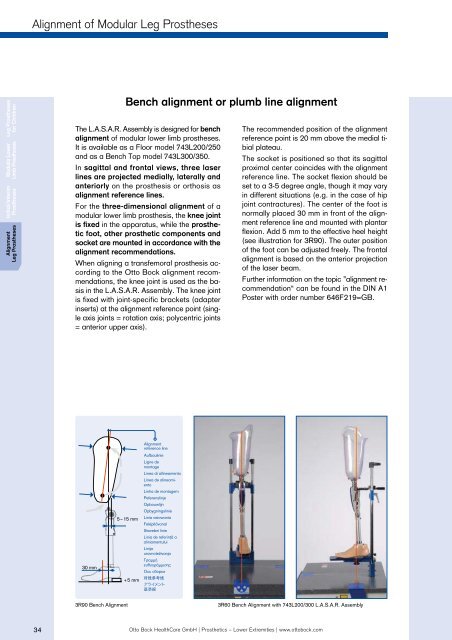
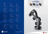
- Page 41: Alignment of Modular Leg Prostheses
- Page 45 and 46: System Height Four steps for checki
- Page 47 and 48: System Height Four steps for checki
- Page 49 and 50: EasySelect 3 steps to an optimal pr
- Page 51 and 52: MOBIS® MOBIS® Simply more quality
- Page 53 and 54: MOBIS® The Otto Bock Mobility Syst
- Page 55 and 56: MOBIS® Transfemoral / TF Hip disar
- Page 57 and 58: Component Combinations: Hip - Knee
- Page 59 and 60: Modular Prosthetic Feet Modular Pro
- Page 61 and 62: Selection Aid Feet for special dema
- Page 63 and 64: Feet for Mobility Grades 1 + 2 Feet
- Page 65 and 66: Geriatric Feet / Mobility Grade 1 P
- Page 67 and 68: Single Axis Feet / Mobility Grade 1
- Page 69 and 70: Single Axis Feet / Mobility Grade 1
- Page 71 and 72: SACH* Feet / Mobility Grades 1 + 2
- Page 73 and 74: SACH* Feet / Mobility Grades 1 + 2
- Page 75 and 76: SACH* Feet / Mobility Grades 1 + 2
- Page 77 and 78: Dynamic Feet / Mobility Grades 1 +
- Page 79 and 80: Greissinger plus / Mobility Grades
- Page 81 and 82: Dynamic Motion / Mobility Grades 2
- Page 83 and 84: Trias / Mobility Grades 2 + 3 Trias
- Page 85 and 86: Feet for Mobility Grades 3 + 4 Feet
- Page 87 and 88: C-Walk® / Mobility Grades 3 + 4 C-
- Page 89 and 90: Axtion® / Mobility Grades 3 + 4 Ax
- Page 91 and 92: Pylon Feet Pylon Feet Pylon feet st
- Page 93 and 94:
Axtion® DP / Mobility Grades 3 + 4
- Page 95 and 96:
Advantage DP2 / Mobility Grades 3 +
- Page 97 and 98:
Accessories for Pylon Feet / Mobili
- Page 99 and 100:
Pylon Feet / Mobility Grades 3 + 4
- Page 101 and 102:
Feet for Limited Clearance Feet for
- Page 103 and 104:
Chopart / Mobility Grades 3 + 4 Cho
- Page 105 and 106:
ProSymes / Mobility Grades 2 + 3 Pr
- Page 107 and 108:
Lo Rider / Mobility Grades 3 + 4 Ac
- Page 109 and 110:
Sports Feet Prosthetic Feet Sport F
- Page 111 and 112:
Sprinter Sprinter The 1E90 Sprinter
- Page 113 and 114:
Modular Adapters Modular Adapters T
- Page 115 and 116:
Tube Adapters 30 mm Tube Adapter St
- Page 117 and 118:
Tube Clamp Adapters 30 mm Tube Clam
- Page 119 and 120:
Tube Clamp Adapters 30 mm Tube Clam
- Page 121 and 122:
Tube Clamp Adapters 34 mm Tube Clam
- Page 123 and 124:
Double Adapter and Connection Adapt
- Page 125 and 126:
Special Adapters Pyramid Adapter wi
- Page 127 and 128:
Lamination Anchors Lamination Ancho
- Page 129 and 130:
Lamination Anchors Lamination Ancho
- Page 131 and 132:
Socket Adapters Socket Adapter with
- Page 133 and 134:
Socket Attachment Blocks Socket Att
- Page 135 and 136:
Modular Transtibial and Transfemora
- Page 137 and 138:
Modular Transtibial and Transfemora
- Page 139 and 140:
Functional Adapters Adapter Functio
- Page 141 and 142:
Rotation Adapters Models Two models
- Page 143 and 144:
Torsion Adapters Models Four models
- Page 145 and 146:
DeltaTwist® DeltaTwist® The loss
- Page 147 and 148:
DeltaTwist® Rotation segments (uni
- Page 149 and 150:
Modular Knee Joints Modular Knee Jo
- Page 151 and 152:
Modular Knee Joints Mechanical Knee
- Page 153 and 154:
Mobility Grade 1 3R33 / 3R17 Modula
- Page 155 and 156:
Mobility Grades 1 + 2 3R36 / 3R20 O
- Page 157 and 158:
Mobility Grades 1 + 2 / 2 + 3 3R90
- Page 159 and 160:
Mobility Grades 2 + 3 The strengths
- Page 161 and 162:
Mobility Grades 2 + 3 3R60 - EBS* -
- Page 163 and 164:
Mobility Grades 2 + 3 Other advanta
- Page 165 and 166:
Mobility Grades 3 + 4 EBS pro Knee
- Page 167 and 168:
Mobility Grades 3 + 4 Other feature
- Page 169 and 170:
Mobility Grades 3 + 4 3R80 - New Ge
- Page 171 and 172:
Mobility Grades 3 + 4 3R80 Aluminum
- Page 173 and 174:
Mobility Grades 3 + 4 The flexion a
- Page 175 and 176:
Mobility Grade 1 Modular Knee Joint
- Page 177 and 178:
Mobility Grades 3 + 4 3R46 Titanium
- Page 179 and 180:
C-Leg® Product Line C-Leg® Produc
- Page 181 and 182:
C-Leg® C-Leg® Knee Joint with Wir
- Page 183 and 184:
C-Leg®compact C-Leg®compact Knee
- Page 185 and 186:
C-Soft and BionicLink C-Soft 4X180
- Page 187 and 188:
System Overview of the C-Leg® Prod
- Page 189 and 190:
C-Leg® Product Line: Warranty and
- Page 191 and 192:
Modular Hip Joints Modular Hip Join
- Page 193 and 194:
Modular Hip Joints 7E7 Aluminum Mod
- Page 195 and 196:
Socket Technologies Socket Technolo
- Page 197 and 198:
Silicone Liners Silicone Liner The
- Page 199 and 200:
Polyurethane Liners Polyurethane-Li
- Page 201 and 202:
Polyurethane Liners AKquire-Liner D
- Page 203 and 204:
Custom Liners Custom Liners Otto Bo
- Page 205 and 206:
Accessories for Liners 719S7 Specia
- Page 207 and 208:
Harmony® System Harmony® System T
- Page 209 and 210:
Harmony® System Overview for Harmo
- Page 211 and 212:
Harmony® e-pulse Features & Benefi
- Page 213 and 214:
Harmony® Function Accessories Acce
- Page 215 and 216:
Harmony® Function Accessories Harm
- Page 217 and 218:
Knee and Thigh Sleeves VASS Knee Sl
- Page 219 and 220:
Shuttle Lock Systems Shuttle Locks
- Page 221 and 222:
Shuttle Lock Systems Important: Som
- Page 223 and 224:
Vacuum Assisted Socket System Singl
- Page 225 and 226:
Vacuum Assisted Socket System Vacuu
- Page 227 and 228:
Vacuum Assisted Socket System Valve
- Page 229 and 230:
Derma Seal Residual Limb Socks Derm
- Page 231 and 232:
Derma Seal Residual Limb Socks Derm
- Page 233 and 234:
Residual Limb Socks CT Function Soc
- Page 235 and 236:
Residual Limb Socks Residual Limb S
- Page 237 and 238:
Compression Shrinker Socks Compress
- Page 239 and 240:
Accessories for Socket Technology P
- Page 241 and 242:
Cosmetic Covers Cosmetic Covers The
- Page 243 and 244:
Foam Covers Please use also the Foa
- Page 245 and 246:
Foam Covers Please use also the Foa
- Page 247 and 248:
Foam Covers Foam cover for hip disa
- Page 249 and 250:
Aesthetic Refinement Surface Techni
- Page 251 and 252:
SoftTouch Stockings SoftTouch Stock
- Page 253 and 254:
Accessories for Modular Lower Limb
- Page 255 and 256:
Accessories for Modular Lower Limb
- Page 257 and 258:
Exoskeletal Leg Prostheses Exoskele
- Page 259 and 260:
Foot Components Foot Components Ott
- Page 261 and 262:
1G6, SACH* and Dynamic Feet Accesso
- Page 263 and 264:
Single Axis Feet Single components
- Page 265 and 266:
Greissinger Foot Pedilan® Sole For
- Page 267 and 268:
Pirogoff Foot Pirogoff Foot Recomme
- Page 269 and 270:
Single Axis Knee-Calf Component wit
- Page 271 and 272:
Long Knee-Calf Component 3P33 Popla
- Page 273 and 274:
Knee-Calf Component 3K9 Plastic 1 K
- Page 275 and 276:
Socket Blocks Socket Blocks Otto Bl
- Page 277 and 278:
Company Firma Straße Street City/
- Page 279 and 280:
General Order Form Fax to the addre
- Page 281 and 282:
Page 2 of 2 C-Leg®compact / C-Leg
- Page 283 and 284:
Polyurethane Custom Liner Shape Plu
- Page 285 and 286:
Polyurethane Custom TEC Liner Shape
- Page 287 and 288:
Otto Bock Silicone Gel Custom Liner
- Page 289 and 290:
Page 1 of 3 (required) Prosthetic F
- Page 291 and 292:
Page 3 of 3 Modular Foot System Cho
- Page 293 and 294:
Page 2 of 2 Sports Prosthesis Feet
- Page 295 and 296:
Customized Foam Covers Fax to the a
- Page 297 and 298:
Glossary Glossary G Greissinger Foo
- Page 299 and 300:
Otto Bock HealthCare GmbH | Prosthe
- Page 301 and 302:
Index Index Article no. Page Articl
- Page 303 and 304:
Index Index Article no. Page Articl
- Page 305 and 306:
Notes
- Page 307 and 308:
Notes
- Page 309 and 310:
© DiskArt 1988 © DiskArt 1988 ©