(NCT) Manual 2010 - Road Safety Authority
(NCT) Manual 2010 - Road Safety Authority
(NCT) Manual 2010 - Road Safety Authority
You also want an ePaper? Increase the reach of your titles
YUMPU automatically turns print PDFs into web optimized ePapers that Google loves.
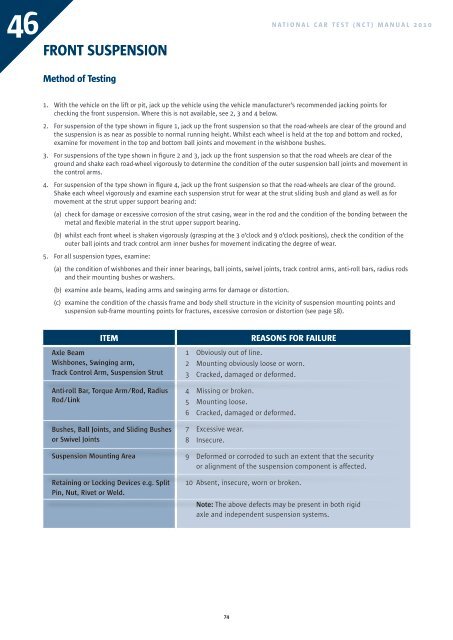
46<br />
FRONT SUSPENSION<br />
NATIONAL CAR TEST (<strong>NCT</strong>) MANUAL <strong>2010</strong><br />
Method of Testing<br />
1. With the vehicle on the lift or pit, jack up the vehicle using the vehicle manufacturer’s recommended jacking points for<br />
checking the front suspension. Where this is not available, see 2, 3 and 4 below.<br />
2. For suspension of the type shown in figure 1, jack up the front suspension so that the road-wheels are clear of the ground and<br />
the suspension is as near as possible to normal running height. Whilst each wheel is held at the top and bottom and rocked,<br />
examine for movement in the top and bottom ball joints and movement in the wishbone bushes.<br />
3. For suspensions of the type shown in figure 2 and 3, jack up the front suspension so that the road wheels are clear of the<br />
ground and shake each road-wheel vigorously to determine the condition of the outer suspension ball joints and movement in<br />
the control arms.<br />
4. For suspension of the type shown in figure 4, jack up the front suspension so that the road-wheels are clear of the ground.<br />
Shake each wheel vigorously and examine each suspension strut for wear at the strut sliding bush and gland as well as for<br />
movement at the strut upper support bearing and:<br />
(a) check for damage or excessive corrosion of the strut casing, wear in the rod and the condition of the bonding between the<br />
metal and flexible material in the strut upper support bearing.<br />
(b) whilst each front wheel is shaken vigorously (grasping at the 3 o’clock and 9 o’clock positions), check the condition of the<br />
outer ball joints and track control arm inner bushes for movement indicating the degree of wear.<br />
5. For all suspension types, examine:<br />
(a) the condition of wishbones and their inner bearings, ball joints, swivel joints, track control arms, anti-roll bars, radius rods<br />
and their mounting bushes or washers.<br />
(b) examine axle beams, leading arms and swinging arms for damage or distortion.<br />
(c) examine the condition of the chassis frame and body shell structure in the vicinity of suspension mounting points and<br />
suspension sub-frame mounting points for fractures, excessive corrosion or distortion (see page 58).<br />
ITEM<br />
Axle Beam<br />
Wishbones, Swinging arm,<br />
Track Control Arm, Suspension Strut<br />
Anti-roll Bar, Torque Arm/Rod, Radius<br />
Rod/Link<br />
Bushes, Ball Joints, and Sliding Bushes<br />
or Swivel Joints<br />
Suspension Mounting Area<br />
Retaining or Locking Devices e.g. Split<br />
Pin, Nut, Rivet or Weld.<br />
REASONS FOR FAILURE<br />
1 Obviously out of line.<br />
2 Mounting obviously loose or worn.<br />
3 Cracked, damaged or deformed.<br />
4 Missing or broken.<br />
5 Mounting loose.<br />
6 Cracked, damaged or deformed.<br />
7 Excessive wear.<br />
8 Insecure.<br />
9 Deformed or corroded to such an extent that the security<br />
or alignment of the suspension component is affected.<br />
10 Absent, insecure, worn or broken.<br />
Note: The above defects may be present in both rigid<br />
axle and independent suspension systems.<br />
74


