Manual Verification Tool IMP - Inheco
Manual Verification Tool IMP - Inheco
Manual Verification Tool IMP - Inheco

You also want an ePaper? Increase the reach of your titles
YUMPU automatically turns print PDFs into web optimized ePapers that Google loves.
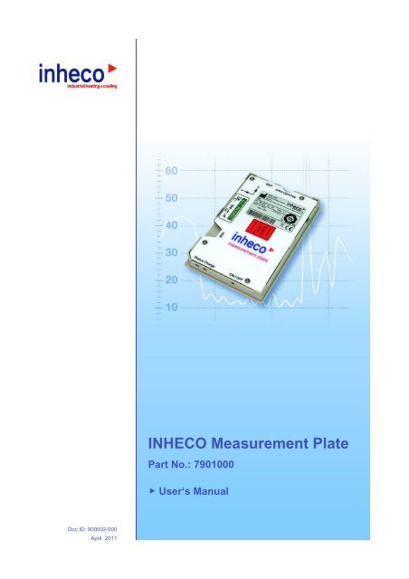
INHECO Measurement Plate<br />
Part No.: 7901000<br />
User‘s <strong>Manual</strong><br />
Doc ID: 900002-000<br />
April 2011
INHECO Industrial Heating and Cooling GmbH reserves the right to modify their<br />
products for quality improvement. Please note that such modifications may not be<br />
documented in this manual.<br />
This manual and the information herein have been assembled with due diligence.<br />
INHECO GmbH does not assume liability for any misprints or cases of damage resulting<br />
from misprints in this manual. If there are any uncertainties, please feel free to contact us.<br />
The brand and product names within this manual are registered trademarks and belong<br />
to the respective titleholders.
TABLE OF CONTENTS<br />
<strong>IMP</strong>ORTANT NOTES . . . . . . . . . . . . . . . . . . . . . . . . . . . . . . . . . . . . . . . . . . . . . . . . . . . . . . . . . . 4<br />
General Information . . . . . . . . . . . . . . . . . . . . . . . . . . . . . . . . . . . . . . . . . . . . . . . . . . . . . . . . . . . 4<br />
Warranty . . . . . . . . . . . . . . . . . . . . . . . . . . . . . . . . . . . . . . . . . . . . . . . . . . . . . . . . . . . . . . . . . . . . 5<br />
How to contact INHECO . . . . . . . . . . . . . . . . . . . . . . . . . . . . . . . . . . . . . . . . . . . . . . . . . . . . . . . . 5<br />
PRODUCT DESCRIPTION . . . . . . . . . . . . . . . . . . . . . . . . . . . . . . . . . . . . . . . . . . . . . . . . . . . . . 6<br />
Intended use . . . . . . . . . . . . . . . . . . . . . . . . . . . . . . . . . . . . . . . . . . . . . . . . . . . . . . . . . . . . . . . . . 6<br />
Components . . . . . . . . . . . . . . . . . . . . . . . . . . . . . . . . . . . . . . . . . . . . . . . . . . . . . . . . . . . . . . . . . 6<br />
Functional Elements . . . . . . . . . . . . . . . . . . . . . . . . . . . . . . . . . . . . . . . . . . . . . . . . . . . . . . . . . . . 7<br />
Labels . . . . . . . . . . . . . . . . . . . . . . . . . . . . . . . . . . . . . . . . . . . . . . . . . . . . . . . . . . . . . . . . . . . . . . 8<br />
Technical Data . . . . . . . . . . . . . . . . . . . . . . . . . . . . . . . . . . . . . . . . . . . . . . . . . . . . . . . . . . . . . . . 9<br />
Battery Lifetime and Runtime . . . . . . . . . . . . . . . . . . . . . . . . . . . . . . . . . . . . . . . . . . . . . . . . . . . 10<br />
Battery Charging . . . . . . . . . . . . . . . . . . . . . . . . . . . . . . . . . . . . . . . . . . . . . . . . . . . . . . . . . . . . 10<br />
Status LED . . . . . . . . . . . . . . . . . . . . . . . . . . . . . . . . . . . . . . . . . . . . . . . . . . . . . . . . . . . . . . . . . 11<br />
SAFETY INSTRUCTIONS . . . . . . . . . . . . . . . . . . . . . . . . . . . . . . . . . . . . . . . . . . . . . . . . . . . . . 12<br />
Product-specific Risks . . . . . . . . . . . . . . . . . . . . . . . . . . . . . . . . . . . . . . . . . . . . . . . . . . . . . . . . 12<br />
Technical Alterations . . . . . . . . . . . . . . . . . . . . . . . . . . . . . . . . . . . . . . . . . . . . . . . . . . . . . . . . . 12<br />
Malfunctions . . . . . . . . . . . . . . . . . . . . . . . . . . . . . . . . . . . . . . . . . . . . . . . . . . . . . . . . . . . . . . . . 12<br />
SOFTWARE INSTALLATION . . . . . . . . . . . . . . . . . . . . . . . . . . . . . . . . . . . . . . . . . . . . . . . . . . . 13<br />
System Requirements . . . . . . . . . . . . . . . . . . . . . . . . . . . . . . . . . . . . . . . . . . . . . . . . . . . . . . . . 13<br />
Windows Vista and Windows 7 . . . . . . . . . . . . . . . . . . . . . . . . . . . . . . . . . . . . . . . . . . . . . . . . . 14<br />
Windows XP . . . . . . . . . . . . . . . . . . . . . . . . . . . . . . . . . . . . . . . . . . . . . . . . . . . . . . . . . . . . . . . . 16<br />
Start <strong>IMP</strong>-Server Software . . . . . . . . . . . . . . . . . . . . . . . . . . . . . . . . . . . . . . . . . . . . . . . . . . . . . 20<br />
Uninstall <strong>IMP</strong> Server Software . . . . . . . . . . . . . . . . . . . . . . . . . . . . . . . . . . . . . . . . . . . . . . . . . . 21<br />
DAILY USE . . . . . . . . . . . . . . . . . . . . . . . . . . . . . . . . . . . . . . . . . . . . . . . . . . . . . . . . . . . . . . . . . 22<br />
Collect Measurement Data . . . . . . . . . . . . . . . . . . . . . . . . . . . . . . . . . . . . . . . . . . . . . . . . . . . . . 22<br />
Abort Measurement . . . . . . . . . . . . . . . . . . . . . . . . . . . . . . . . . . . . . . . . . . . . . . . . . . . . . . . . . . 23<br />
Load Measured Data from the <strong>IMP</strong> Unit . . . . . . . . . . . . . . . . . . . . . . . . . . . . . . . . . . . . . . . . . . . 23<br />
Save Measured Data . . . . . . . . . . . . . . . . . . . . . . . . . . . . . . . . . . . . . . . . . . . . . . . . . . . . . . . . . 23<br />
Retrieve Stored Measurement Data . . . . . . . . . . . . . . . . . . . . . . . . . . . . . . . . . . . . . . . . . . . . . . 23<br />
Print Measurement Data . . . . . . . . . . . . . . . . . . . . . . . . . . . . . . . . . . . . . . . . . . . . . . . . . . . . . . 23<br />
Export Measurement Data . . . . . . . . . . . . . . . . . . . . . . . . . . . . . . . . . . . . . . . . . . . . . . . . . . . . . 24<br />
Test of Temperature and Humidity Sensors . . . . . . . . . . . . . . . . . . . . . . . . . . . . . . . . . . . . . . . . 24<br />
Test Shake Sensors . . . . . . . . . . . . . . . . . . . . . . . . . . . . . . . . . . . . . . . . . . . . . . . . . . . . . . . . . . 24<br />
Charging the Battery . . . . . . . . . . . . . . . . . . . . . . . . . . . . . . . . . . . . . . . . . . . . . . . . . . . . . . . . . 24<br />
Turn off the <strong>IMP</strong> Unit . . . . . . . . . . . . . . . . . . . . . . . . . . . . . . . . . . . . . . . . . . . . . . . . . . . . . . . . . 25<br />
USER INTERFACE . . . . . . . . . . . . . . . . . . . . . . . . . . . . . . . . . . . . . . . . . . . . . . . . . . . . . . . . . . 26<br />
Menu „File“ . . . . . . . . . . . . . . . . . . . . . . . . . . . . . . . . . . . . . . . . . . . . . . . . . . . . . . . . . . . . . . . . . 26<br />
Menu „<strong>IMP</strong>“ . . . . . . . . . . . . . . . . . . . . . . . . . . . . . . . . . . . . . . . . . . . . . . . . . . . . . . . . . . . . . . . . . 27<br />
Screen „Configure“ . . . . . . . . . . . . . . . . . . . . . . . . . . . . . . . . . . . . . . . . . . . . . . . . . . . . . . . . . . . 27<br />
Screen „Evaluate“ . . . . . . . . . . . . . . . . . . . . . . . . . . . . . . . . . . . . . . . . . . . . . . . . . . . . . . . . . . . . 32<br />
Screen „Real-time View“ . . . . . . . . . . . . . . . . . . . . . . . . . . . . . . . . . . . . . . . . . . . . . . . . . . . . . . 37<br />
Time and Date Settings . . . . . . . . . . . . . . . . . . . . . . . . . . . . . . . . . . . . . . . . . . . . . . . . . . . . . . . 39<br />
<strong>IMP</strong> Unit Sounds . . . . . . . . . . . . . . . . . . . . . . . . . . . . . . . . . . . . . . . . . . . . . . . . . . . . . . . . . . . . 40<br />
<strong>IMP</strong> Unit Info . . . . . . . . . . . . . . . . . . . . . . . . . . . . . . . . . . . . . . . . . . . . . . . . . . . . . . . . . . . . . . . . 40<br />
Menu Settings . . . . . . . . . . . . . . . . . . . . . . . . . . . . . . . . . . . . . . . . . . . . . . . . . . . . . . . . . . . . . . 40<br />
Menu Info . . . . . . . . . . . . . . . . . . . . . . . . . . . . . . . . . . . . . . . . . . . . . . . . . . . . . . . . . . . . . . . . . . 46<br />
Sensor Positions and Shake Directions . . . . . . . . . . . . . . . . . . . . . . . . . . . . . . . . . . . . . . . . . . . 47<br />
MAINTENANCE . . . . . . . . . . . . . . . . . . . . . . . . . . . . . . . . . . . . . . . . . . . . . . . . . . . . . . . . . . . . . 48<br />
Decontamination and Cleaning . . . . . . . . . . . . . . . . . . . . . . . . . . . . . . . . . . . . . . . . . . . . . . . . . 48<br />
Calibration . . . . . . . . . . . . . . . . . . . . . . . . . . . . . . . . . . . . . . . . . . . . . . . . . . . . . . . . . . . . . . . . . 48<br />
Transportation and Storage . . . . . . . . . . . . . . . . . . . . . . . . . . . . . . . . . . . . . . . . . . . . . . . . . . . . 48<br />
Repair . . . . . . . . . . . . . . . . . . . . . . . . . . . . . . . . . . . . . . . . . . . . . . . . . . . . . . . . . . . . . . . . . . . . . 48<br />
Spare Parts . . . . . . . . . . . . . . . . . . . . . . . . . . . . . . . . . . . . . . . . . . . . . . . . . . . . . . . . . . . . . . . . 48<br />
Software Updates . . . . . . . . . . . . . . . . . . . . . . . . . . . . . . . . . . . . . . . . . . . . . . . . . . . . . . . . . . . . 48<br />
Disposal . . . . . . . . . . . . . . . . . . . . . . . . . . . . . . . . . . . . . . . . . . . . . . . . . . . . . . . . . . . . . . . . . . . 49<br />
Appendix . . . . . . . . . . . . . . . . . . . . . . . . . . . . . . . . . . . . . . . . . . . . . . . . . . . . . . . . . . . . . . . . . . . 50<br />
EC - Declaration of Conformity . . . . . . . . . . . . . . . . . . . . . . . . . . . . . . . . . . . . . . . . . . . . . . . . . . 50<br />
INHECO 3
1 <strong>IMP</strong>ORTANT NOTES<br />
1.1 General Information<br />
Read the user instructions completely. The instructions for use explain the intended use<br />
of the INHECO Measurement Plate (<strong>IMP</strong> Unit). In case of failure to observe the manual's<br />
instructions, injury or product damage cannot be excluded.<br />
Missing or insufficient knowledge of the manual leads to loss of liability against INHECO<br />
GmbH.<br />
This manual is part of the <strong>IMP</strong> Unit and must be retained until the Unit is disposed and<br />
passed on to the new user when the Unit is sold or lent.<br />
The <strong>IMP</strong> Unit meets the acknowledged rules of technology and complies with today's<br />
standards.<br />
They must be followed in order to ensure safe handling of the unit.<br />
Security-related warnings in this manual are classified into three hazard levels:<br />
- The signal word WARNING indicates hazards which - without precautionary measures<br />
- can result in serious injury or even death.<br />
- The signal word CAUTION is given to indicate hazards which - without precautionary<br />
measures - can result in minor to moderate injuries or could disturb functioning.<br />
- The signal word NOTE stands for the general precautionary measures that are to be<br />
observed to avoid damaging the device when using it.<br />
Please contact the manufacturer in case you do not understand something within this<br />
manual.<br />
Your opinion about this manual provides us with valuable insights on how we can serve<br />
you better. Please do not hesitate to direct your comments to us:<br />
➜ How to contact INHECO, page 5.<br />
INHECO 4
1.2 Warranty<br />
Two years from date of shipment. Any damage caused by operating the <strong>IMP</strong> Unit outside<br />
the specifications and guidelines will lead to the loss of warranty. A broken seal at the<br />
screwing will also lead to the loss of warranty.<br />
1.3 How to contact INHECO<br />
INHECO GmbH<br />
Address Fraunhoferstr. 11<br />
82152 Martinsried<br />
Germany<br />
Telephone - Sales +49 89 / 899593-101<br />
Fax +49 89 / 899593-499<br />
E-Mail – Sales<br />
sales@inheco.com<br />
E-Mail – Technical Hotline<br />
techhotline@inheco.com<br />
Website<br />
www.inheco.com<br />
INHECO 5
2 PRODUCT DESCRIPTION<br />
2.1 Intended use<br />
The <strong>IMP</strong> Unit is designed specifically for use in Life Science and In Vitro Diagnostics. The<br />
<strong>IMP</strong> Unit is designed to verify temperature and shake settings of laboratory equipment.<br />
When using the <strong>IMP</strong> Unit in a Biosafety Laboratory Environment, the user of the <strong>IMP</strong> Unit<br />
is responsible for labeling the device according to the WHO Laboratory Biosafety <strong>Manual</strong><br />
(ISBN 92 4154650 6). The user is furthermore responsible for operating the <strong>IMP</strong> Unit<br />
depending on the biosafety level regulations according to the WHO Laboratory Biosafety<br />
<strong>Manual</strong>.<br />
2.2 Components<br />
Figure 1 presents a survey over the components included in the delivery.<br />
6<br />
4<br />
5<br />
1<br />
2<br />
3<br />
Fig. 1: Components<br />
(1) <strong>IMP</strong> Unit<br />
(2) USB Memory Stick<br />
(contains Software and <strong>Manual</strong>s)<br />
(3) USB Cable<br />
(4) Battery Charger<br />
(incl. Adapter Euro, GB and US)<br />
(5) Case<br />
(6) Calibration Certificate<br />
INHECO 6
2.3 Functional Elements<br />
Figure 2 introduces the terminology of the <strong>IMP</strong> Unit's functional elements.<br />
7<br />
8<br />
13<br />
9<br />
10 11 12<br />
Fig. 2: Functional Elements<br />
(7) Micro SD-Card Slot<br />
(8) USB Interface<br />
(9) IrDA Interface<br />
(10) Status LED<br />
(11) Battery Charge LED<br />
(12) ON/OFF Switch<br />
(13) Calibration Mark<br />
INHECO 7
2.4 Labels<br />
The labels on the <strong>IMP</strong> Unit and the Battery Charger contain important technical indica -<br />
tions. The labels must not be removed. If a label has become illegible or falls off, it has to<br />
be replaced by a corresponding new label with matching information. New labels can be<br />
ordered from INHECO.<br />
14<br />
13<br />
17<br />
15<br />
16<br />
Fig. 3: Labels<br />
13<br />
14<br />
Calibration mark<br />
Identification plate<br />
15<br />
16<br />
Identification plate<br />
Identification plate<br />
17<br />
Sealing<br />
INHECO 8
2.5 Technical Data<br />
<strong>IMP</strong> Unit<br />
Dimensions Length 128 mm 5.04 inch<br />
Width 86 mm 3.39 inch<br />
Height 15 mm 0.59 inch<br />
Weight (excluding cables) 100 g 0.273 lbs<br />
Input Voltage (USB-Connector) 5 Vdc, ±10%<br />
Input Current<br />
0.2 A<br />
Fuse<br />
internal<br />
Interface USB 1.1 or 2.0<br />
Micro-SD-Card 512 MB to 2 GB<br />
IrDA<br />
Protection Category IP 20<br />
Temperature Sensors<br />
10 digital sensors<br />
Shaker Sensor (3 axis) max: ±6g<br />
Humidity Sensor<br />
0-100% rel. humidity<br />
Battery Charger<br />
Input Voltage<br />
100 to 240 V/AC<br />
Output Voltage<br />
5 Vdc<br />
Input Current<br />
0.4 A<br />
Output Current<br />
1.6 A<br />
Safety Class 2<br />
Power Frequency<br />
47 to 63 Hz<br />
Fuse<br />
internal, resettable<br />
Environmental Conditions<br />
Max. Operation Height 2000 m 6562 ft<br />
Tolerable Relative Humidity Operation 100 %, not condensing<br />
Battery charging 80 %, not condensing<br />
Transportation and storage 80 %, not condensing<br />
Temperature Operation +4 to +60°C +41 to +140°F<br />
Battery charging 0 to +40°C +32 to +104°F<br />
Transportation and storage -10 to +60°C +14 to +140°F<br />
Temperature precision 1) Temperature precision ±0.1°C<br />
Temperature accuracy ±0.1°C<br />
Movement precision 2) Frequence precision ±0.5 Hz<br />
Frequence accuracy ±5 %<br />
1) Calibration in water bath. May vary depending on ambient conditions, target temperature and measured device.<br />
2) Measured with the same <strong>IMP</strong>.<br />
INHECO 9
2.6 Battery Lifetime and Runtime<br />
At 23°C ± 5°C [73.4°F ± 9°F], the lifetime of the Li/Po battery lasts for at least 500 char -<br />
ging cycles. After that, the battery capacity can decrease to 60% of its original capacity.<br />
It is advisable to avoid unnecessarily long use of the <strong>IMP</strong> Unit at high temperatures during<br />
measurement.<br />
The runtime of the <strong>IMP</strong> Unit depends on the charging level of the battery and the temper -<br />
ature during measurement. The following chart shows the relationship between temper -<br />
ature and runtime.<br />
2.7 Battery Charging<br />
To charge the internal battery of the <strong>IMP</strong> Unit, connect the Unit to the power supply. The<br />
battery must be charged via the power supply. Do not charge the battery via the USB in -<br />
terface of a computer. During charging, the charge LED indicates constant green light.<br />
The LED blinks green when the charging process has finished.<br />
If the ambient temperature exceeds +40°C [+104°F], charging will stop automatically and<br />
the charge LED is blinking red.<br />
In case of a battery charger malfunction the charge LED is shining red.<br />
A nearly full discharge of the battery, e.g. after storing the <strong>IMP</strong> Unit for a long time with<br />
empty battery, causes a malfunction of the charge LED. After connecting the <strong>IMP</strong> Unit to<br />
charge the battery, the LED does not light. During a time of approx. 3 hours the <strong>IMP</strong> Unit<br />
is testing and conditioning the battery. When the charging process starts, the LED indica -<br />
tor turns back to constant green.<br />
INHECO 10
2.8 Status LED<br />
Color Type of flashing Description<br />
1s 2s 3s<br />
off<br />
<strong>IMP</strong> Unit is off<br />
green<br />
<strong>IMP</strong> Unit is on<br />
blue<br />
<strong>IMP</strong> Unit is receiving or sending a message<br />
green Measurement is initialized. Measurement will start af -<br />
ter delay time is expired.<br />
red<br />
Measurement is initialized, waiting to press the ON/<br />
OFF button.<br />
yellow<br />
ON/OFF is getting pressed.<br />
red ON/OFF button pressed for more then 5 seconds -<br />
blinks red just before switching off<br />
red<br />
Temperature measurement is running<br />
red<br />
Acceleration measurement is running<br />
yellow<br />
Measurement completed<br />
Color Timing Description<br />
2s 4s 6s<br />
yl, gn, r<br />
ON/OFF Button getting pressed.<br />
Releasing the ON/OFF Button during yellow:<br />
no action<br />
Releasing the ON/OFF Button during green:<br />
Measurement will start after delay time is expired.<br />
Releasing the ON/OFF Button during red: <strong>IMP</strong> Unit is<br />
switched off<br />
INHECO 11
3 SAFETY INSTRUCTIONS<br />
3.1 Product-specific Risks<br />
WARNING<br />
Follow the safety instructions given below in order to eliminate danger for user and<br />
device.<br />
- The <strong>IMP</strong> Unit and its accessory must not come into contact with water or chemicals.<br />
- The device must not be used in environments with risk of explosion.<br />
- Never open the housing of the net adapter or the <strong>IMP</strong> Unit. There is no maintenance<br />
work within the units to be done by the user.<br />
- Burning Hazard: Do not touch the Glass/Ceramic Plate at the bottom side after<br />
measuring. You could seriously burn your skin. The material‘s temperature can reach<br />
up to 60°C (140°F) depending on the measuring temperature! It takes a while to cool<br />
off after the unit has been used. Only touch the plate when it is cooled off.<br />
- The device must not be used if the <strong>IMP</strong> Unit, the power adapter housing or the power<br />
cable show visible signs of damage.<br />
- Original power supply and cables provided by INHECO have to be used to guarantee<br />
safe and proper operation.<br />
- Make sure that the electrical specifications on the label at the rear panel of the battery<br />
charger meet your local situation.<br />
- Always make sure that the unit is disconnected from the wall power outlet during<br />
measurement.<br />
- Never connect or remove the power plug with wet hands.<br />
3.2 Technical Alterations<br />
- Do not alter the product. Any modification or change which is not approved by the<br />
manufacturer, leads to the loss of guaranty.<br />
- The original parts are especially designed for the <strong>IMP</strong> Unit. Parts provided by other<br />
suppliers are not tested and can impair the functionality of the <strong>IMP</strong> Unit.<br />
- For damages which may occur due to the usage of non original parts, liability is<br />
excluded by INHECO GmbH.<br />
3.3 Malfunctions<br />
- In case of a malfunction, switch off and disconnect the <strong>IMP</strong> Unit immediately.<br />
Make sure to inform the authorized person in charge.<br />
INHECO 12
4 SOFTWARE INSTALLATION<br />
The following sections list the technical requirements and the stages of action for install -<br />
ing the <strong>IMP</strong> Server software. Please follow the instructions in the given order, depending<br />
on the used operating system. Ignoring the correct order may cause complications during<br />
installation. In case you have deviated from the correct process, we suggest you to dein -<br />
stall the <strong>IMP</strong> Server software and to re-install it a second time.<br />
4.1 System Requirements<br />
- Operating system: Windows XP, Windows Vista or Windows 7<br />
- Free USB port (USB 1.1 or 2.0)<br />
- Minimal display resolution: 800 x 600 pixel<br />
INHECO 13
4.2 Windows Vista and Windows 7<br />
NOTE<br />
Do not connect the <strong>IMP</strong> Unit to the computer before the installation routine asks you to<br />
do so.<br />
4.2.1 Installation<br />
• Connect the accompanying USB Memory Stick to the PC and open the following file:<br />
<strong>IMP</strong>Server_Setup_x.x.x_Vista7<br />
The installation will start automatically.<br />
• Follow the instructions in the dialogues given below.<br />
Additional dialogues could appear, depending on Windows configuration, user rights<br />
and firewall. For questions about these, please contact your administrator.<br />
INHECO 14
After the software and driver installation is completed, you can connect the <strong>IMP</strong> Unit to<br />
the PC. When connecting, the pre-installed driver will be loaded automatically.<br />
Afterwards, the following Windows status message will appear at the lower right:<br />
Then, the <strong>IMP</strong> Unit is given a free COM port by the operating system automatically.<br />
Before initialising the program, the connected COM port has to be known (cf. ➜ Tab<br />
„Connection“, page 41).<br />
Then please continue with ➜ Start <strong>IMP</strong>-Server Software, page 20.<br />
INHECO 15
4.3 Windows XP<br />
NOTE<br />
Do not connect the <strong>IMP</strong> Unit to the computer before the installation routine asks you to<br />
do so.<br />
4.3.1 Installation<br />
• Connect the USB Memory Stick to the PC and open the following file:<br />
<strong>IMP</strong>Server_Setup_x.x.x_XP. The installation will start automatically.<br />
• Follow the instructions in the dialogs given below.<br />
Additional dialogs could appear, depending on Windows configuration, user rights and<br />
firewall. For questions about these, please contact your administrator.<br />
INHECO 16
INHECO 17
After the software and driver installation is completed, you can connect the <strong>IMP</strong> Unit to<br />
the PC. Windows will ask you now to install the driver.<br />
• Connect the <strong>IMP</strong> Unit to the PC via USB cable.<br />
The following dialog box will open.<br />
.<br />
• Make sure that Install the software automatically (Recommended) is activated and<br />
click on the Next button.<br />
.<br />
INHECO 18
• Click on the button Continue Anyway.<br />
The following dialog box will open.<br />
.<br />
• Click on the button Finish.<br />
Afterwards, the following Windows status message will appear at the lower right:<br />
Then the <strong>IMP</strong> Unit is given a free COM port by the operating system automatically.<br />
Please note that the correct COM port is set in the <strong>IMP</strong> Server Software<br />
(for further information cf. ➜ Tab „Connection“, page 41).<br />
Please continue with ➜ Start <strong>IMP</strong>-Server Software, page 20.<br />
INHECO 19
4.4 Start <strong>IMP</strong>-Server Software<br />
• Make sure that the <strong>IMP</strong> Unit is connected.<br />
• Open the software by double-clicking on the icon shown here.<br />
After the installation, this icon appears on the desktop or under<br />
Start > All Programs > <strong>Inheco</strong> > <strong>IMP</strong>Server.<br />
The following screen is shown:<br />
If the COM-Port cannot be identified (e.g. at initial installation or after modification of<br />
connected hardware), an error message is issued indicating that the COM port is not<br />
found.<br />
In this case, make sure that the <strong>IMP</strong> Unit is correctly connected and assign the COM-Port<br />
➜ Tab „Connection“, page 41.<br />
If the internal time settings of the <strong>IMP</strong> Unit and the computer's time settings do not corre -<br />
spond, a further dialog box will appear after connecting the Unit<br />
➜ Time and Date Settings, page 39.<br />
INHECO 20
4.5 Uninstall <strong>IMP</strong> Server Software<br />
NOTE<br />
The <strong>IMP</strong> Unit must be disconnected from the computer before deinstalling the<br />
<strong>IMP</strong>-Server.<br />
• Click on Start > All Programs in the taskbar.<br />
• Select <strong>IMP</strong> Server.<br />
• Select Uninstall.<br />
• Follow the instructions in the dialogue boxes.<br />
INHECO 21
5 DAILY USE<br />
➜ page 40<br />
➜ page 28<br />
➜ page 29<br />
➜ page 30 ➜ page 31<br />
In this chapter, you will find a description of the most frequent working processes with<br />
the <strong>IMP</strong> Unit. The screen is divided in several areas that will be explained in detail in<br />
the following sections. The red text bubbles list the corresponding page for each sec -<br />
tion.<br />
5.1 Collect Measurement Data<br />
In the following, a typical measurement procedure with the <strong>IMP</strong> Unit is given.<br />
• Connect the <strong>IMP</strong> Unit to the PC via USB cable.<br />
• Start the <strong>IMP</strong> Server ➜ Start <strong>IMP</strong>-Server Software, page 20.<br />
• Select <strong>IMP</strong> > Configure.<br />
• Select the required conditions for starting the measurement data acquisition under<br />
Start Conditions.<br />
• Select in the checkboxes if you wish to measure Temperature / Humidity and/or<br />
Shaking.<br />
• Set the required parameters for the measurement you wish to run:<br />
➜ Section „Temperature / Humidity“, page 30<br />
➜ Section „Shaking“, page 31<br />
• If necessary, you can enter a comment concerning the measurement in the the Notes<br />
area.<br />
• Enter your initials into the field Tester Initials (2-3 letters).<br />
Without tester initials the measurement cannot start.<br />
• Click on the button Start.<br />
• Disconnect the <strong>IMP</strong> Unit from the computer.<br />
• Place the <strong>IMP</strong> Unit at the measuring location.<br />
NOTE<br />
The <strong>IMP</strong> Unit may only be operated in a flat and even position.<br />
INHECO 22
After the selected start delay, the measurement starts. If you selected a manual start,<br />
keep the ON/OFF button pressed for 1-2 seconds with an unpointed object (e.g. a pen<br />
or pencil), until the status LED lights green.<br />
During measurement the status LED is flashing red ➜ Status LED, page 11.<br />
The termination of the measurement is indicated by an acoustic signal ➜ <strong>IMP</strong> Unit<br />
Sounds, page 40, and blue light flashing on the status LED ➜ Status LED, page 11.<br />
5.2 Abort Measurement<br />
If you don't wish to continue with an ongoing measurement, you can cancel it easily by<br />
overwriting it with a new one ➜ Status LED, page 11.<br />
It can also be stopped by switching the <strong>IMP</strong> Unit off or by reading the data previously<br />
recorded ➜ Turn off the <strong>IMP</strong> Unit, page 25.<br />
5.3 Load Measured Data from the <strong>IMP</strong> Unit<br />
After completing the measurement, the data stored in the <strong>IMP</strong> Unit can be loaded as<br />
follows:<br />
• Connect the <strong>IMP</strong> Unit to the PC via USB cable.<br />
• Start the <strong>IMP</strong> Server ➜ Start <strong>IMP</strong>-Server Software, page 20.<br />
• Select <strong>IMP</strong> > Evaluate.<br />
• Click on the button Load measured data<br />
While loading, the dialog with the number of measuring points to be loaded will appear.<br />
After the loading process, the dialog box will close and the area<br />
Evaluate > Summary will display a summary of the collected data.<br />
5.4 Save Measured Data<br />
• Select File > Save File.<br />
• Enter a filename and select the target file location.<br />
• Click on the button Save.<br />
The measurement incl. all data and diagrams will be saved; it can be retrieved at a<br />
later date.<br />
5.5 Retrieve Stored Measurement Data<br />
For the retrieval of stored data, the <strong>IMP</strong> Unit does not have to be connected to the PC.<br />
• Double-click with the left mouse button on the <strong>IMP</strong> File you wish to view.<br />
The stored data collection is on display.<br />
5.6 Print Measurement Data<br />
When printing measurement data, you can select different settings (only the summary or<br />
together with charts) to be printed ➜ Tab „Format“, page 42.<br />
• Select File > Print Protocol.<br />
• Click on the button Print.<br />
• Select printer and required settings in the printing dialog.<br />
The protocol consists of 1 or 2 pages.<br />
INHECO 23
5.7 Export Measurement Data<br />
• Select File > Export to csv-File.<br />
• Enter a filename and select the target file location.<br />
• Click on the button Save.<br />
The measurement will be saved as csv file (i.e. comma-separated values) which can<br />
be opened with standard software, e.g. Microsoft Excel or a text editor.<br />
5.8 Test of Temperature and Humidity Sensors<br />
The sensors can be checked easily and quickly with a plausibility check under the menu<br />
item Real-Time view :<br />
• Connect the <strong>IMP</strong> Unit to the PC via USB cable.<br />
• Start the <strong>IMP</strong> Server ➜ Start <strong>IMP</strong>-Server Software, page 20.<br />
• Select <strong>IMP</strong> > Real-Time view.<br />
Real-Time view will open and the tab Temperature / Humidity is pre-selected.<br />
The online measurement will start automatically.<br />
• Check if every single one of 11 sensors (10 temperature sensors and 1 humidity<br />
sensor) is being recorded and the values of the temperature sensors differ from each<br />
other only within a plausible range.<br />
The legend on the right hand side lists all sensors. You can select them one by one by<br />
individual checkboxes. The sensors' positions can be displayed under the menu item<br />
Info > Sensor Positions ➜ Sensor Positions and Shake Directions, page 47.<br />
5.9 Test Shake Sensors<br />
The sensors' funcionality can be checked easily and quickly<br />
under the menu item Real-Time view:<br />
• Connect the <strong>IMP</strong> Unit to the PC via USB cable.<br />
• Open the <strong>IMP</strong> Server.<br />
• Select <strong>IMP</strong> > Real-Time view.<br />
Real-Time view will open and the tab Temperature / Humidity is pre-selected.<br />
• Select the tab Inclination.<br />
• Put the <strong>IMP</strong> Unit to rest on each of its six sides and wait each time, until the display<br />
shows a stabilized measuring. For reasons of gravity, each of the sensors has to<br />
measure an acceleration of 1g. This is shown by the fact that a value indicates +1g<br />
resp. -1g.<br />
Is this the case in all six directions, the shake sensors perform correctly.<br />
5.10 Charging the Battery<br />
To make sure that an ongoing measurement does not stop for lack of power capacity in<br />
the <strong>IMP</strong>, you should always check the state of charge before running a measurement.<br />
Pay attention to the information on the battery status ➜ <strong>IMP</strong> Unit Info, page 40 display.<br />
Charging:<br />
• Connect the country-specific adapter to the Battery Charger.<br />
During charging, the charge LED shows permanent green light. When charging is<br />
over, the LED is flashing green.<br />
Note that charging the <strong>IMP</strong> via computer will be interrupted during energy-saving<br />
periods (Snooze or sleeping mode).<br />
Therefore, charging by mains plug is suggested.<br />
INHECO 24
5.11 Turn off the <strong>IMP</strong> Unit<br />
• Keep the ON/OFF button of the <strong>IMP</strong> Unit pressed with an unpointed object (e.g. a pen)<br />
for at least five seconds, until the status LED lights red.<br />
After releasing the switch, the status LED blinks red for another two seconds and then<br />
the <strong>IMP</strong> Unit switches off.<br />
INHECO 25
6 USER INTERFACE<br />
In the following sections, menus and screens of the <strong>IMP</strong> Server software are explained in<br />
systematic order. The sections serve as a reference and provide details on the software's<br />
operating elements.<br />
6.1 Menu „File“<br />
New <strong>IMP</strong> connec -<br />
tion<br />
Open File<br />
Recent Files<br />
Save File<br />
Export to csv-File<br />
Print Preview<br />
Print Protocol<br />
Exit<br />
If the <strong>IMP</strong> Unit was not connected to the computer when starting the soft -<br />
ware, or the connection has been cut temporarily, you can connect it<br />
using this menu item.<br />
To retrieve stored measurement values.<br />
To show a list of 9 files previously opened.<br />
To save actually called data.<br />
To export actually measured values (incl. all data for evaluation) to a csv<br />
file. This can be opened with standard software, e.g. Microsoft Excel or<br />
a text editor.<br />
To show a print preview of the measured data set presently shown. The<br />
first screen displays the header, <strong>IMP</strong> information and summary, the<br />
second one temperature, humidity and/or shake charts.<br />
You can only see charts in the preview and print them, if the item with<br />
details under Settings > Options is activated ➜ Tab „Connection“,<br />
page 41.<br />
To print the measurement presently called. The first screen displays the<br />
header, <strong>IMP</strong> information and summary, the second one temperature,<br />
humidity and/or shake charts.<br />
Charts are only included in the print, if you have activated the function<br />
with details under Settings > Options ➜ Tab „Connection“, page 41.<br />
To close the <strong>IMP</strong> Server.<br />
INHECO 26
6.2 Menu „<strong>IMP</strong>“<br />
Configure<br />
To set the measurement parameters and start<br />
measuring.<br />
➜ Screen<br />
„Configure“, page 27<br />
Evaluate To load and evaluate measurements. ➜ Screen<br />
„Evaluate“, page 32<br />
Real-time view<br />
Time and Date<br />
Settings...<br />
Turn on <strong>IMP</strong><br />
Sounds<br />
Show <strong>IMP</strong> Info<br />
Real-time view is to check the functionality of<br />
temperature, humidity and shake sensors<br />
quickly and easily.<br />
To configure date and time settings and to<br />
handle time differences between <strong>IMP</strong> Unit and<br />
PC.<br />
To turn on or off the sounds of the <strong>IMP</strong> repor -<br />
ting the end of a measurement or a low state<br />
of charge.<br />
Displays the <strong>IMP</strong> Unit Info about the actually<br />
connected <strong>IMP</strong>, its time and date settings and<br />
state of charge.<br />
➜ Screen „Real-time<br />
View“, page 37<br />
➜ Time and Date<br />
Settings, page 39<br />
➜ <strong>IMP</strong> Unit Sounds,<br />
page 40<br />
➜ <strong>IMP</strong> Unit Info,<br />
page 40<br />
6.3 Screen „Configure“<br />
• Select <strong>IMP</strong> > Configure (available only if an <strong>IMP</strong> Unit is connected).<br />
The following screen is displayed.<br />
➜ page 40<br />
➜ page 28<br />
➜ page 29<br />
➜ page 30 ➜ page 31<br />
The screen is divided in several areas that will be explained in detail in the following<br />
sections. The red text bubbles list the corresponding page for each section.<br />
INHECO 27
6.3.1 Section „Configure Measuring“<br />
Presettings<br />
Radio buttons to set temperature and shaking conditions of a<br />
measurement.<br />
None To reload the settings of the last measure -<br />
ment from the connected <strong>IMP</strong><br />
User Settings 1<br />
User Settings 2<br />
...<br />
User Settings 10<br />
To select from user-specific settings with indi -<br />
vidual measurement conditions. Settings are<br />
saved for subsequent use<br />
Start Conditions ➜ Section „Start Conditions“, page 29<br />
Temperature / Humidity ➜ Section „Temperature / Humidity“, page 30<br />
Shaking ➜ Section „Shaking“, page 31<br />
Notes<br />
Tester Initials<br />
Start<br />
The tester can enter notes up to 50 characters. These notes are<br />
saved during the measurement process and will be part of the pro -<br />
tocol.<br />
To identify the person performing the measurement. Two or three<br />
characters have to be entered before the measurement can be<br />
started.<br />
If the settings are complete, this button needs to be pressed starting<br />
the measurement according to the settings made in the Start Conditions<br />
➜ Screen „Configure“, page 27.<br />
INHECO 28
6.3.2 Section „Start Conditions“<br />
In this section, different ways to start an <strong>IMP</strong> measurement can be selected.<br />
In ... seconds After pressing the button Configure and start, the run starts after the se -<br />
lected number of seconds. Values between 1 and 999 seconds (about 16<br />
minutes) can be entered.<br />
... seconds after<br />
pressing<br />
ON/OFF switch<br />
On Time: ...<br />
On target<br />
temperature<br />
1) Not yet available<br />
The measurement starts n seconds after the ON/OFF switch of the <strong>IMP</strong><br />
Unit has been pressed for 1-2 seconds. Values between 1 and 999 sec -<br />
onds (about 16 minutes) can be entered.<br />
The measurement starts at the entered time 1) . It refers to the intern time<br />
of the <strong>IMP</strong> Unit, which can be seen in the <strong>IMP</strong> Info ➜ Menu Info, page 46.<br />
The measurement starts when the entered target temperature has been<br />
achieved 1) .<br />
INHECO 29
6.3.3 Section „Temperature / Humidity“<br />
In this area, you can select the settings for temperature and humidity during measure -<br />
ment.<br />
Checkbox<br />
Measure<br />
points<br />
Meauring<br />
interval<br />
Total<br />
measuring time<br />
To activate the temperature and humidity measurement.<br />
Use the slide control to set the number of measuring points. The number<br />
is displayed in the box above the slide control.<br />
Use the slide control to set the interval (in seconds) between the measure<br />
points. The number is displayed in the box above the slide control.<br />
The total measuring time is the result of the chosen measurement points<br />
and intervals.<br />
INHECO 30
6.3.4 Section „Shaking“<br />
In this section, the settings of the shake measurement can be selected.<br />
Checkbox<br />
Frequency (range)<br />
Amplitude (range)<br />
Total measuring time<br />
To activate the shake measurement.<br />
Use the slide control to set the measuring range for the expected<br />
shake frequency.<br />
Use the slide control to set the measuring range for the expected<br />
shake amplitude.<br />
The total measuring time is calculated from the frequency range.<br />
INHECO 31
6.4 Screen „Evaluate“<br />
• Select <strong>IMP</strong> > Evaluate<br />
The screen Evaluate is used for importing and viewing actual measurement data in the<br />
<strong>IMP</strong> Unit or for viewing data stored in PC files. It can be selected via Menu > <strong>IMP</strong> > Evaluate.<br />
Initially, the summary is displayed. It gives an overview of the measurement results<br />
and additional information, such as starting and ending time, comments etc.<br />
In the Temperature section at the top left, the starting and ending time of the measure -<br />
ment and the number of measuring points are shown. Further down, details on the mean<br />
values, standard deviation and minimum/maximum temperatures are given. Here, the<br />
values of all sensors are combined. The individual values of the 10 temperature sensors<br />
are visible on the right hand side of the Temperature section.<br />
In the Shaking section, information on the measured frequency and maximum amplitude<br />
of movements in x and y directions and the mean radius is displayed.<br />
In the Humidity section, you can see the average value - with standard deviation - as well<br />
as minimum and maximum values.<br />
In the field Notes, the notes entered before starting the measurement and, next to it, the<br />
tester initials are displayed. Moreover, the present time and date are indicated.<br />
Details on temperature, humidity and shaking can be viewed by selecting the relevant tab.<br />
By clicking on the button Load Measurement, data currently saved in the <strong>IMP</strong> can be<br />
read.<br />
INHECO 32
6.4.1 Tab „Temperature / Humidity details“<br />
The Temperature/Humidity diagram shows the chronological course of all measured val -<br />
ues of the 10 temperature sensors and the humidity sensor (gray, thicker line).<br />
To zoom in, you can select a<br />
rectangular part of the chart by<br />
the left mouse button.<br />
The chosen extract will be<br />
displayed in a chart-filling format<br />
after releasing the mouse button.<br />
In the context menu (right mouse<br />
button), there is the item<br />
Un-Zoom.<br />
By activating this, the chart gets<br />
back to its original size.<br />
The zoom factor can be modified<br />
via mouse wheel.<br />
NOTE<br />
The temperature is shown in degree Celsius (°C). Shifting to Fahrenheit (°F) is possible<br />
in Settings > Options > Units.<br />
On the right side of the chart, you can see the legend. This legend identifies all 10 tem -<br />
perature sensors and the humidity sensor (Hum) with their matching display colours in the<br />
chart. By clicking the checkboxes, they can be selected or deselected individually.<br />
The sensor positions can be seen under the menu item Info > Sensor Positions or on<br />
page 47 in this manual.<br />
At the bottom left, there is a slide control to define the number of values that may form a<br />
moving average. In the sample chart, the set value is „1“. The standard settings are to be<br />
selected in Settings > Options... ➜ Tab „Connection“, page 41.<br />
INHECO 33
At the top left, you can select other display features. These are summarized in the<br />
following table:<br />
Normal View<br />
First time derivative<br />
Second time derivative<br />
Integral of the function<br />
Average and sensors‘ deviation from mean value<br />
The context menu of the chart provides additional features for the measurement data<br />
processing:<br />
• Right mouse-click on a temperature and humidity chart.<br />
The following context menu is shown.<br />
Copy<br />
Copy Values to<br />
Clipboard...<br />
Save Image As...<br />
Page Setup...<br />
Print...<br />
Use section to<br />
evaluate...<br />
Crop measure<br />
data<br />
Show Point<br />
Values<br />
Show Zoom<br />
Area Values<br />
Un-Zoom<br />
Undo All Zoom/<br />
Pan<br />
Set Scale to<br />
Default<br />
To copy the diagram to the clipboard.<br />
To copy the temperature values to the clipboard.<br />
A dialog is opened to select if the values are to be saved at the beginning<br />
or at the end of the selected section or both.<br />
Moreover, you can define how measured values should be separated<br />
from each other (separator).<br />
To save the diagram as image file (emf file) to a user-defined location.<br />
To specify format settings for printing the chart.<br />
To print the chart.<br />
Customer-specific check of the measurement results. 1)<br />
To crop measured data to the currently selected section or zoomed focus.<br />
This action cannot be undone.<br />
If this function is activated, you can view the measurement points‘ relevant<br />
time, temperature and humidity values on mouseover.<br />
To define the zoomed area of the chart exactly, its numerical values can<br />
be indicated here.<br />
To undo the last zoom or shifting action.<br />
To undo all zoom or shifting actions so far.<br />
This will set the most appropriate zoom or display area for the actual chart.<br />
1) On customer's demand<br />
INHECO 34
6.4.2 Tab „Shaking details“<br />
The Shaking area shows three diagrams.<br />
In the chart Shake figure the shake movement is shown as figure (locus curve). Here,<br />
shape and regularity of the shake movement can be evaluated in its x and y directions.<br />
The chart Time response shows the amplitude of movement components in both axes on<br />
a timeline. The red line stands for the x axis movement, the green one for the y axis.<br />
In the chart Frequency response you can see the components‘ range of the shaking<br />
movement. Again the red line stands for the x direction, green for the y direction.<br />
To zoom in, you can select a rectangular part of the chart by the left mouse button.<br />
The chosen extract will be displayed in a chart-filling format after releasing the mouse<br />
button.<br />
In the context menu (right mouse button), there is a function Un-Zoom.<br />
By activating this, the chart gets back to its original size. The size of the image can be<br />
modified by clicking the mousewheel on the respective chart.<br />
The context menu of the charts provides other functions for processing the measured<br />
data:<br />
• Right mouseclick on a Shake chart.<br />
The following context menu is shown.<br />
Copy<br />
To copy the right-clicked chart to the clipboard.<br />
Save Image As... To save the right-clicked chart as image file (emf file) to a user-defined lo -<br />
cation.<br />
Page Setup...<br />
Print...<br />
To specify format settings for printing the chart.<br />
To print the right-clicked chart.<br />
INHECO 35
Show Point<br />
Values<br />
Un-Zoom<br />
Undo All Zoom/<br />
Pan<br />
Set Scale to<br />
Default<br />
Is this feature enabled, placing the cursor on a measurement point will<br />
show corresponding values in x and y axis.<br />
It has to be activated for each chart individually.<br />
To undo the last zoom or shifting action.<br />
To undo all zoom or shifting actions so far.<br />
This will set the most appropriate zoom or display area for the actual chart.<br />
This feature can be applied, for example, if a chart shows only a part of<br />
the measured values and you wish to view the entire measuring range.<br />
INHECO 36
6.5 Screen „Real-time View“<br />
Real-time view helps to check the functionality of temperature, humidity and shake sen -<br />
sors quickly and easily.<br />
6.5.1 Tab „Temperature / Humidity“<br />
• Select <strong>IMP</strong> > Real-time view (available only if an <strong>IMP</strong> Unit is connected).<br />
• Select the tab Temperature / Humidity.<br />
The following screen is displayed.<br />
The sample chart shows the temperature scale on the left side and the humidity scale on<br />
the right side. The x axis displays the time in seconds during measurement. The time unit<br />
in Real-Time view is invariable.<br />
To zoom in, you can select a rect -<br />
angular part of the chart by the left<br />
mouse button.<br />
The chosen extract will be dis -<br />
played after releasing the mouse<br />
button in a chart filling format.<br />
In the context menu, there is the<br />
item Un-Zoom.<br />
By activating this, the chart gets<br />
back to its original size. The zoom<br />
factor can be modified via mouse<br />
wheel.<br />
On the right side of the chart, you can see the legend. This legend identifies all 10 tem -<br />
perature sensors and the humidity sensor (Hum) with their matching display colours in the<br />
chart. By clicking the checkboxes, they can be selected or deselected individually.<br />
In the field below the legend, you can select the display's time slot in seconds.<br />
To balance short-term fluctuations and to improve the display in the chart, a moving<br />
average may be formed from a arbitrary number of values.<br />
In Real-Time view, the number of values can be modified only under<br />
Settings > Options > Other ➜ Tab „Other“, page 45.<br />
INHECO 37
6.5.2 Tab „Inclination“<br />
• Select <strong>IMP</strong> > Real-time view (available only if an <strong>IMP</strong> Unit is connected).<br />
• Select the tab Inclination.<br />
The following screen is displayed.<br />
On the left side, the force actually acting on the sensors is shown. Is the <strong>IMP</strong> Unit<br />
positioned on its underside (e.g. like image right), so gravity acts on the z sensor with<br />
-1.0g.<br />
Since no force is acting on x and y sensors in resting position, the chart shows exact<br />
vertical, perpendicular position (red dot).<br />
Further information ➜ Test Shake Sensors, page 24.<br />
INHECO 38
6.6 Time and Date Settings<br />
• Select <strong>IMP</strong> > Time and Date Settings... (available only if an <strong>IMP</strong> Unit is connected).<br />
Following dialogs can be selected by the relevant tab.<br />
Check<br />
To indicate a potential time difference between <strong>IMP</strong> Unit and computer. Chose from<br />
the possibilities offered to handle the situation.<br />
The actual time difference is shown below the radio buttons.<br />
If time difference to <strong>IMP</strong><br />
greater ... minutes<br />
To specify a time difference for operating one of the fol -<br />
lowing options.<br />
auto update <strong>IMP</strong> time Is this option enabled and the pre-selected time differ -<br />
ence has been exceeded, the <strong>IMP</strong> Server will synchro -<br />
nize time automatically to the PC time setting when it is<br />
connected. Time data belonging to measurements<br />
stored in the <strong>IMP</strong> is not affected.<br />
ask user (show this<br />
window)<br />
Is this option enabled and the pre-selected time differ -<br />
ence has been exceeded, the user will be asked upon<br />
connection of the <strong>IMP</strong> by opening this dialog<br />
-for further proceeding<br />
and<br />
-manual modification of time setting is possible<br />
do nothing<br />
If the time difference between <strong>IMP</strong> Unit and computer is<br />
insignificant and can be ignored, this is the right option.<br />
Time /<br />
Date<br />
Indicates time / date settings.<br />
PC<br />
PC time / date. For comparison only (no data input).<br />
<strong>IMP</strong><br />
Sync <strong>IMP</strong> to PC<br />
Done/<br />
Set <strong>IMP</strong> date / time<br />
<strong>IMP</strong> Unit time / date for manual entry.<br />
Synchronizes the <strong>IMP</strong> Unit on the PC‘s time / date.<br />
Time or date settings entered manually can be saved<br />
by clicking this button.<br />
INHECO 39
6.7 <strong>IMP</strong> Unit Sounds<br />
The <strong>IMP</strong> Unit emits the following sound signals:<br />
Sound timing<br />
2min<br />
Description<br />
Measurement terminated.<br />
Battery charge state very low, <strong>IMP</strong> will switch off<br />
automatically after approx. 30 minutes.<br />
<strong>IMP</strong> sounds are activated on default. Sounds can be switched on and off under the menu<br />
item „<strong>IMP</strong>“.<br />
6.8 <strong>IMP</strong> Unit Info<br />
This area shows specific information on <strong>IMP</strong>-Hardware, battery status, date and time of<br />
the <strong>IMP</strong> Unit.<br />
• Select <strong>IMP</strong> > Show <strong>IMP</strong> Info (available only if an <strong>IMP</strong> Unit is connected).<br />
The following area is displayed on the main screen.<br />
Serial Number<br />
Bootstrap<br />
Version<br />
Application<br />
Version<br />
Calibration<br />
Mark<br />
Date<br />
Time<br />
Battery Status<br />
Displays the serial number of the connected <strong>IMP</strong> Unit.<br />
In case of questions or problems with the <strong>IMP</strong> Unit, please state these<br />
version numbers.<br />
To display the last calibration date of the <strong>IMP</strong> Unit. For detailed informa -<br />
tion see calibration certificate contained in the shipment.<br />
To display the internal date and time of the <strong>IMP</strong> Unit. Please note that<br />
time and date settings may be different from PC settings ➜ Time and<br />
Date Settings, page 39.<br />
The color of this button (green, yellow or red) displays the state of<br />
charge of the <strong>IMP</strong> internal battery:<br />
Red: less than 40 % of the battery capacity<br />
Yellow: 40 % - 60 %<br />
Green: 60 % - 100 %<br />
6.9 Menu Settings<br />
Options... Connection ➜ Tab „Connection“, page 41<br />
Format ➜ Tab „Format“, page 42<br />
Units ➜ Tab „Units“, page 43<br />
Behavior ➜ Tab „Behavior“, page 44<br />
Other ➜ Tab „Other“, page 45<br />
Service Menu The service menu is password protected and for service staff only.<br />
INHECO 40
6.9.1 Tab „Connection“<br />
• Select Settings > Options... > Connection<br />
The following dialog is displayed.<br />
<strong>IMP</strong> hardware is<br />
connected to<br />
COM-Port<br />
Autodetect <strong>IMP</strong>s<br />
To show a list of available COM ports.<br />
Set the correct COM port of your <strong>IMP</strong> Unit here.<br />
Scan all COM ports for connected <strong>IMP</strong> Units.<br />
Note: Other PC-connected USB devices may produce unexpected<br />
reactions to the scanning process.<br />
At program start and in daily use of the <strong>IMP</strong> Unit, the assigned COM port should be<br />
known.<br />
Otherwise, you can use the following procedure in order to identify the assigned COM<br />
port.<br />
COM port identification<br />
• Connect the <strong>IMP</strong> Unit via USB cable to the PC.<br />
• Click on Start in the taskbar.<br />
• Enter the following character string into the search field:<br />
devmgmt.msc<br />
• Press Enter.<br />
The device manager is displayed.<br />
• Select the subitem Ports (COM & LPT):<br />
The <strong>IMP</strong> Unit should be found in the list of assigned ports.<br />
Behind the <strong>IMP</strong> Units name, you can see the connected COM port.<br />
It is important to note the COM port for future operations; then the device manager may<br />
be closed.<br />
INHECO 41
6.9.2 Tab „Format“<br />
• Select Settings > Options... > Connection<br />
The following dialog is displayed.<br />
Date Format long Date is shown in long form.<br />
Example: Monday, April 04, 2011<br />
long<br />
Date is shown in short form (MM/DD/YYYY).<br />
Example: 04/04/2011<br />
Time Format long Long form: Seconds are displayed.<br />
long<br />
Short form: Seconds are not displayed.<br />
Print Protocol with Details Printout of measurement summary includes charts.<br />
with Details<br />
Charts are not included.<br />
INHECO 42
6.9.3 Tab „Units“<br />
• Select Settings > Options... > Units<br />
The following dialog is displayed.<br />
Temperature<br />
Unit<br />
°C / °F The temperature is indicated in °F.<br />
°C / °F The temperature is indicated in °C.<br />
Shaking Unit Hz / rpm Shake frequency is indicated in revolutions per<br />
minute [rpm].<br />
Hz / rpm<br />
Shake frequency is indicated in Hertz [Hz].<br />
Time Units Auto The timeline of the charts shows the relative time<br />
Seconds<br />
Minutes<br />
Hours<br />
that passed since the start. You can chose whether<br />
the time unit will be adjusted automatically or<br />
manually.<br />
Absolute<br />
The timeline of the charts shows the absolute time.<br />
INHECO 43
6.9.4 Tab „Behavior“<br />
• Select Settings > Options... > Behavior<br />
The following dialog is displayed.<br />
Show <strong>IMP</strong>-Info never <strong>IMP</strong>-Info is not indicated.<br />
never <strong>IMP</strong>-Info is displayed when an <strong>IMP</strong> Unit is connect -<br />
ed.<br />
Minimize to Tray Minimizing reduces the <strong>IMP</strong> program window to an<br />
<strong>IMP</strong> icon in the system tray.<br />
Measurement<br />
Order<br />
to Tray<br />
shake first<br />
shake first<br />
Minimizing reduces the <strong>IMP</strong> program window to an<br />
<strong>IMP</strong> icon in the taskbar.<br />
Temperature and humidity are measured after the<br />
shaking.<br />
Temperature and humidity are measured before<br />
the shaking.<br />
INHECO 44
6.9.5 Tab „Other“<br />
• Select Settings > Options... > Other<br />
The following dialog is displayed.<br />
Moving average<br />
of<br />
Determines the number of values for averaging. The average helps to<br />
get a better chart display.<br />
The value „1“ is set as default. With this setting, there is no averaging;<br />
measured values are displayed without the mean value<br />
➜ Tab „Other“, page 45.<br />
Moving average<br />
The following sample measuring will illustrate the enhanced visualization based on a<br />
moving average. The number of values for averaging is displayed in the red frame.<br />
Without moving average:<br />
INHECO 45
Moving average of 20 values:<br />
NOTE<br />
Excessive averaging leads to chronological distortion of the measurement signal.<br />
6.10 Menu Info<br />
Help<br />
To pop up a short instruction for using the <strong>IMP</strong> Unit.<br />
Sensor positions Shows the location of the temperature<br />
sensors on the <strong>IMP</strong> Unit.<br />
Shake directions To display the coordinate system un -<br />
derlying the evaluation of the shake<br />
measurement.<br />
➜ Sensor Positions and<br />
Shake Directions, page 47<br />
The coordinate system is also printed<br />
on the <strong>IMP</strong> Unit's top.<br />
About<br />
Gives information about the software<br />
version and copyright.<br />
INHECO 46
6.11 Sensor Positions and Shake Directions<br />
These menu items give a survey of the temperature sensors' positions and of the coordi -<br />
nate system which lies at the base of the evaluation.<br />
• Select Info > Sensor positions bzw. Select Info > Shake directions<br />
Following overviews are displayed.<br />
INHECO 47
7 MAINTENANCE<br />
7.1 Decontamination and Cleaning<br />
CAUTION<br />
During cleaning and decontamination, the <strong>IMP</strong> Unit has to be disconnected from the wall<br />
outlet.<br />
NOTE<br />
Make sure that no liquid enters the inside of the <strong>IMP</strong> Unit.<br />
The <strong>IMP</strong> Unit can be decontaminated by disinfection with formaldehyde or ethylene oxide<br />
gas.<br />
For cleaning the surface of the <strong>IMP</strong> Unit, ethanol (70 %) can be used.<br />
7.2 Calibration<br />
For proper thermal and shaker performance of the <strong>IMP</strong> Unit and the connected devices,<br />
it is recommended to re-calibrate the <strong>IMP</strong> once a year. Depending on the application,<br />
shorter calibration intervals may be required. Re-calibration should be done by accredited<br />
calibration laboratories only. Re-calibration by a calibration laboratory can be done via<br />
INHECO. INHECO offers firmware updates free of charge with each re-calibration via<br />
INHECO. The <strong>IMP</strong> unit initially comes only with a temperature calibration certification.<br />
Shaker calibration can be ordered separately.<br />
7.3 Transportation and Storage<br />
It is recommended to keep the original packaging and <strong>IMP</strong> Protection Case. The <strong>IMP</strong> Unit<br />
may only be transported and stored in its protection case with all accessories.<br />
7.4 Repair<br />
The <strong>IMP</strong> Unit must be repaired by INHECO only.<br />
INHECO will only accept decontaminated <strong>IMP</strong> Units ➜ Decontamination and Cleaning,<br />
page 48, returned in the original packing and <strong>IMP</strong> Protection Case, for repair, re-calibra -<br />
tion, firmware update, or other maintenance.<br />
Please ask sales@inheco.com for the return procedure before you return an <strong>IMP</strong> unit to<br />
INHECO.<br />
Devices exposed to biosafety level 3 and 4 environments will not be accepted by INHECO<br />
for return.<br />
7.5 Spare Parts<br />
Spare Parts for the <strong>IMP</strong> Unit must be ordered from INHECO.<br />
7.6 Software Updates<br />
For updates of the <strong>IMP</strong> Server software, contact: sales@inheco.com ➜ How to contact<br />
INHECO, page 5. INHECO offers software updates free of charge with each re-calibra -<br />
tion via INHECO.<br />
INHECO 48
7.7 Disposal<br />
The Unit has to be disposed of in accordance with environmental and biosafety directives.<br />
You have to arrange for correct electric waste disposal following actual safety regulations<br />
for your country.<br />
The <strong>IMP</strong> Unit is RoHS and WEEE compliant.<br />
INHECO 49
Appendix<br />
EC - Declaration of Conformity<br />
EC - Declaration of Conformity<br />
in accordance with Directive 2006/95/EC, 93/68ECC and 2004/108/EC<br />
Product:<br />
INHECO Measurement Plate (<strong>IMP</strong>)<br />
Part No: 7901000<br />
Standards (Safety): IEC/EN 61010-1: 2001<br />
CAN/CSA 22.2 No 61010-1: 2004<br />
UL 61010-1:2004<br />
IEC/EN 61010-2-101: 2002<br />
CAN/CSA 22.2 No 61010-2-101: 2004<br />
Standards (EMC):<br />
EN55011:2007 +A2:2007<br />
EN 60601-1-2:2007-12<br />
EN 61000-3-2:2006<br />
EN 61000-3-3:1995 +A1:2001 +A2:2005<br />
EN 61000-4-1:2007<br />
EN 61000-4-2:1995 +A1:1998 +A2:2001<br />
EN 61000-4-3:2006 +A1:2008<br />
EN 61000-4-4:2004<br />
EN 61000-4-6:2007 + Corrigendum 2007-08<br />
EN 61000-4-8:1993<br />
EN 61000-4-11:2004<br />
EN 61326-1:2006<br />
IEC/CISPR 11:2003 +A1:2004, +A:2006<br />
IEC 60601-1-2:2007 modified<br />
IEC 61000-3-2:2005<br />
IEC 61000-3-3:1994 +A1:2001 +A2:2005<br />
IEC 61000-4-1:2006<br />
IEC 61000-4-2:1995 +A1:1998 +A2:2000<br />
IEC 61000-4-3:2006 +A1:2007<br />
IEC 61000-4-4:2004<br />
IEC 61000-4-6:2003 +A1:2004 +A2:2006<br />
IEC 61000-4-8:1993 +A1:2000<br />
IEC 61000-4-11:2004<br />
IEC 61326-1:2005<br />
This product complies with the essential requirements of the Low Voltage Directive 2006/95/EC and<br />
EMC directive 2004/108/EC, when used for its intended purpose.<br />
Manufacturer address: INHECO Industrial Heating and Cooling GmbH<br />
Fraunhoferstr. 11<br />
82152 Martinsried<br />
Germany<br />
Phone, Fax: Tel.: +49 (0) 89 899 593 -100<br />
Fax: +49 (0) 89 899 593 -499<br />
Martinsried, February 21th, 2011<br />
Place and date of issue<br />
Günter Tenzler, Managing Director<br />
TD_C3_11-02-21_7901000 EC-Declaration of Conformity_02.docx<br />
INHECO 50