Marley Sustainable Drainage Rainwater Harvesting Kits ... - BHL.co.uk
Marley Sustainable Drainage Rainwater Harvesting Kits ... - BHL.co.uk
Marley Sustainable Drainage Rainwater Harvesting Kits ... - BHL.co.uk
Create successful ePaper yourself
Turn your PDF publications into a flip-book with our unique Google optimized e-Paper software.
RAINWATER HARVESTING KITS - INSTALLATION MANUAL<br />
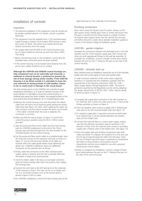
Installation of <strong>co</strong>ntrols<br />
Important :<br />
• The electrical installation of this equipment must be carried out<br />
by suitably qualified persons. If in doubt, <strong>co</strong>nsult a qualified<br />
electrician.<br />
• This equipment must be supplied from a 13A switched power<br />
supply through a residual circuit breaker (RCD) having a rated<br />
trip current of 30mA. The switch must isolate the live and<br />
neutral <strong>co</strong>nnections from the supply.<br />
• The supply cable from the RCD to the <strong>co</strong>ntrol housing must<br />
be of a type suitable for external use and must have a 240V,<br />
13A rating.<br />
• Before <strong>co</strong>mmencing work on the installation, ensure that the<br />
intended mains <strong>co</strong>nnection point has been isolated.<br />
• If the <strong>co</strong>ntrol housing is to be located some distance from the<br />
service duct, cables should be run in <strong>co</strong>nduit.<br />
Although the USW100 and USW200 <strong>co</strong>ntrol housings are<br />
fully waterproof and can be externally wall mounted, a<br />
sheltered or internal location is preferred to prevent the<br />
risk of frost damage during winter months. If the USW100<br />
housing is to be fitted outside it is advisable to leave the<br />
unit switched on during periods of <strong>co</strong>ld weather. Failure<br />
to do so <strong>co</strong>uld result in damage to the circuit board.<br />
The level sensing system on the USW200 unit is sensitive to large<br />
temperature fluctuations, so in order to maintain accuracy of the<br />
visual indicator it is advisable to locate the <strong>co</strong>ntrol housing in a<br />
sheltered area away from direct sunlight. Any exposed sections of the<br />
level sensing tube should ideally be run in insulated Equator pipe.<br />
a) Remove the <strong>co</strong>ntrol housing <strong>co</strong>ver and dis<strong>co</strong>nnect the ribbon<br />
cable from the fascia circuit board by gently pulling the brown<br />
<strong>co</strong>llar back (See figure 12). Note: when replacing the cable, the<br />
silver <strong>co</strong>ntacts must face down towards the fascia circuit board<br />
- if the cable is twisted when the <strong>co</strong>ver is replaced, the<br />
<strong>co</strong>nnection is in<strong>co</strong>rrect.<br />
b) Mark and drill the wall as shown on figure 12 and fix the<br />
<strong>co</strong>ntrol housing in position using the No.6 x 30mm screws<br />
provided.<br />
c) Tape the pump and float switch cables (and the level sensing<br />
tube for USW200 installations) to the end of the 15mm<br />
Equator pipe and feed through from the inlet chamber to the<br />
intended location for the <strong>co</strong>ntrol housing.<br />
d) Cut the pump and float switch cables to a suitable length, bare<br />
the ends and <strong>co</strong>nnect to the respective terminals as shown on<br />
figure 12. Ensure that the outer sheaths of all cables are<br />
inserted within the cable glands before hand tightening the<br />
gland nuts. USW200 installations require an additional<br />
<strong>co</strong>nnection to the solenoid valve as shown<br />
e) Finally, make the <strong>co</strong>nnection to the 240V switched mains<br />
supply, leaving it isolated until the tank is partially filled and<br />
the system is ready to be <strong>co</strong>mmissioned.<br />
f) Insert the ribbon cable in the fascia circuit board <strong>co</strong>nnector,<br />
push the brown locking <strong>co</strong>llar back into position, then replace<br />
the housing <strong>co</strong>ver.<br />
g) Connect the vent tube to the left hand port on the underside<br />
of the housing as shown. The tube can be cut to length and<br />
run to a <strong>co</strong>nvenient location such as the services pipe to<br />
prevent ingress of dirt or water.<br />
h) For USW200 installations, <strong>co</strong>nnect the level sensing tube to the<br />
right hand port on the underside of the housing.<br />
Plumbing <strong>co</strong>nnections<br />
Note: when using the Equator push fit system, always cut the<br />
pipe square using a <strong>Marley</strong> pipe cutter or similar and ensure that<br />
the pipe is inserted into the fitting socket to a depth of 25mm.<br />
An Equator pipe support sleeve must be inserted into the pipe<br />
end before the joint is made. More detailed installation guidance<br />
is given in the Equator Design & Installation guide.<br />
USW100 – garden irrigation<br />
Complete the <strong>co</strong>nnection between the discharge hose in the inlet<br />
chamber and the 15mm Equator supply pipe, then <strong>co</strong>nnect the<br />
other end with appropriate fittings to the wall tap assembly. To<br />
<strong>co</strong>mplete the installation, <strong>co</strong>nnect a length of 4mm bore tubing<br />
between the port on the ‘T’ fitting to the port on the side of the<br />
<strong>co</strong>ntrol housing.<br />
USW200 – domestic back up<br />
Note: domestic back up installations require the use of a loft mounted<br />
header tank with a dual supply of mains and recycled water.<br />
In order to prevent pollution of the mains water supply by<br />
backflow it is essential that the installation <strong>co</strong>mplies with the<br />
requirements of the Statutory Instrument 1999, No 1148 – ‘<br />
Water Supply (Water Fittings) Regulations 1999’. The level of<br />
protection specified by the Regulations can be met by adopting<br />
the design requirements of BS EN 13077: 2003, relevant details<br />
of which are given in figure 13.<br />
a) Complete the supply pipe <strong>co</strong>nnection in the inlet chamber as<br />
for USW100, then <strong>co</strong>nnect the other end to the ‘Y’ filter of the<br />
fittings assembly as shown on figure 3<br />
b) From the isolation valve <strong>co</strong>nnect a supply with a Torbeck type<br />
inlet valve to the loft mounted header tank (See figure 13)<br />
c) If a separate supply pipe is required to provide recycled water<br />
to an external tap, it can be inserted between the isolation<br />
valve and the header tank<br />
d) Connect the solenoid valve to a mains water supply, making<br />
sure that the electrical <strong>co</strong>nnection tags are pointing in the<br />
direction of flow. From the solenoid valve <strong>co</strong>nnect a se<strong>co</strong>ndary<br />
supply with a Torbeck valve to the header tank. (See figure 13)<br />
e) Once the supply, feed and overflow <strong>co</strong>nnections have been<br />
made and tested, fit a Byelaw 50 insulation kit to the tank and<br />
lid and lag all exposed pipework within the loft space. Note:<br />
the use of Torbeck type inlet valves is preferred to <strong>co</strong>nventional<br />
ball valves as they provide a more positive shut-off<br />
characteristic and are more suitable for use with a pressure<br />
based pump <strong>co</strong>ntrol system.<br />
f) Finally, to <strong>co</strong>mplete the installation, <strong>co</strong>nnect a length of 4mm<br />
bore tubing between the port on the ‘T’ fitting to the port on<br />
the side of the <strong>co</strong>ntrol housing.<br />
12


