Marley Sustainable Drainage Rainwater Harvesting Kits ... - BHL.co.uk
Marley Sustainable Drainage Rainwater Harvesting Kits ... - BHL.co.uk
Marley Sustainable Drainage Rainwater Harvesting Kits ... - BHL.co.uk

You also want an ePaper? Increase the reach of your titles
YUMPU automatically turns print PDFs into web optimized ePapers that Google loves.
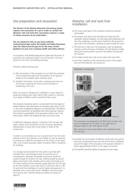
RAINWATER HARVESTING KITS - INSTALLATION MANUAL<br />
Site preparation and excavation<br />
The fitment of the <strong>Marley</strong> <strong>Rainwater</strong> <strong>Harvesting</strong> system<br />
requires the excavation of a pit in order to <strong>co</strong>ntain the<br />
Waterloc cells and tank liner. Excavation requires a range<br />
of safety measures to be undertaken.<br />
You are advised to refer to your local authority<br />
environmental dept and/or the Health and Safety Executives<br />
web site: http://www.hse.gov.<strong>uk</strong> for the most current<br />
guidance (or your own <strong>co</strong>mpany health and safety adviser)<br />
In ac<strong>co</strong>rdance with Building Regulations Approved Document H,<br />
excavations for soakaway systems must be located a minimum<br />
distance of 5m from any building boundary.<br />
Therefore, before starting work:<br />
Waterloc cell and tank liner<br />
installation<br />
a) The <strong>co</strong>arse sand base of the excavation should be tamped<br />
and levelled.<br />
b) The bottom and sides of the excavation are lined with the<br />
geotextile material supplied, one strip being laid lengthways and<br />
the other widthways. Lay the excess material on the ground on<br />
each side of the excavation, allowing an equal overlap all round.<br />
c) The tank liner is laid out in the excavation, over the geotextile<br />
material, and the first layer of Waterloc HD cells (black) installed,<br />
leaving the centre position vacant for the bottom housing and<br />
riser sections.<br />
d) The edges should abut and <strong>co</strong>rners align with each other.<br />
e) Lock them together at the intersecting <strong>co</strong>rners of the upper<br />
face with the Waterloc cell <strong>co</strong>nnectors.<br />
Waterloc <strong>co</strong>nnectors<br />
a) Plan the location of the excavation to suit both the proximity<br />
of the building boundary and the elevation of the ground<br />
relative to the available water <strong>co</strong>llection point.<br />
b) Establish the location of any other underground services to<br />
the site by <strong>co</strong>ntacting the various service providers or<br />
<strong>co</strong>nducting a CAT scan.<br />
Note: the system is designed for installation in areas subject to<br />
pedestrian loading only. Light vehicle traffic requires a minimum<br />
<strong>co</strong>ver depth of 900mm which would limit filter access.<br />
Figure 4<br />
The rainwater harvesting system is <strong>co</strong>nstructed from three layers of<br />
<strong>Marley</strong> Waterloc cells and requires an excavation plan area of 2.4m<br />
x 1.8m, with an additional allowance of approximately 150-200mm<br />
around the perimeter for backfilling with <strong>co</strong>arse granular material.<br />
The minimum overall depth of the excavation needs to be 2.15m,<br />
which allows 100mm for levelling the base with <strong>co</strong>arse sand.<br />
If additional soakaway capacity is required in the top layer, the<br />
upper volume of the excavation can be increased, typically by<br />
adding blocks of three cells to the length or width of the<br />
<strong>co</strong>nstruction.<br />
In order to ac<strong>co</strong>mmodate any rise in ground level from the water<br />
<strong>co</strong>llection point, the inspection <strong>co</strong>ver height can also be adjusted<br />
to provide up to 850mm soil depth over the surface of the upper<br />
cells. (2.5m overall excavation depth, including 100mm allowance<br />
for levelling)<br />
It is strongly re<strong>co</strong>mmended that the system is only fed with<br />
rainwater from roof drainage outlets to avoid the risk of<br />
<strong>co</strong>ntamination. <strong>Rainwater</strong> downpipe <strong>co</strong>nnections should be<br />
routed through the 250mm silt trap, UG60 provided to prevent<br />
debris entering the inlet chamber and to reduce the build up of<br />
silt. When setting out the rainwater supply pipe from the silt trap<br />
to the inlet chamber, ensure that there is a minimum fall of 1:80.<br />
To assist with the installation of <strong>co</strong>ntrol cables and pipework it is<br />
advisable to fit a long radius bend, UBL488 to the service pipe<br />
from ground level. General setting out details are shown on<br />
figure 6.<br />
Figure 5<br />
The <strong>co</strong>nnectors are designed to be fitted ‘back to back’ and<br />
can be <strong>co</strong>nfigured for use either on an upper face or<br />
between layers of cells. (See figures 4 & 5)<br />
NB: <strong>co</strong>nnectors must not be fitted to the underside of the<br />
first cell layer.<br />
f) Assemble the se<strong>co</strong>nd layer of Waterloc (blue) cells and pull the<br />
tank liner and geotextile taut over the vertical faces, backfilling<br />
around the edges of the excavation with granular material to<br />
within approximately 150mm of the upper cell surface.<br />
g) The backfill should be lightly <strong>co</strong>mpacted at each stage.<br />
6