
You also want an ePaper? Increase the reach of your titles
YUMPU automatically turns print PDFs into web optimized ePapers that Google loves.
<strong>Delcom</strong> <strong>Products</strong> <strong>Inc</strong>.<br />
USBIOHID Datasheet<br />
Revision 8 – 04/12/2010<br />
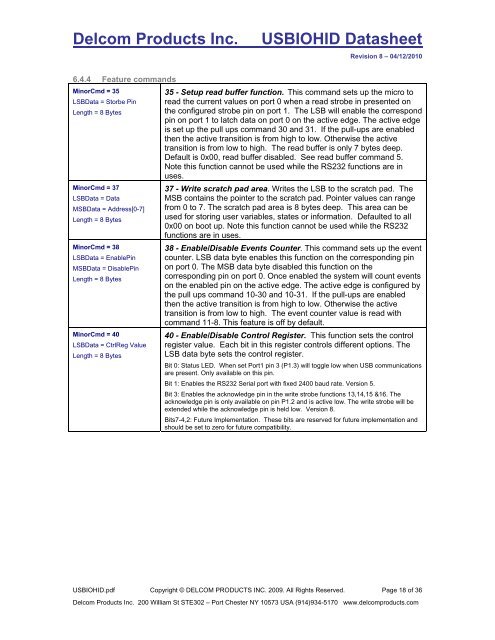
6.4.4 Feature commands<br />
MinorCmd = 35<br />
LSBData = Storbe Pin<br />
Length = 8 Bytes<br />
MinorCmd = 37<br />
LSBData = Data<br />
MSBData = Address[0-7]<br />
Length = 8 Bytes<br />
MinorCmd = 38<br />
LSBData = EnablePin<br />
MSBData = DisablePin<br />
Length = 8 Bytes<br />
MinorCmd = 40<br />
LSBData = CtrlReg Value<br />
Length = 8 Bytes<br />
35 - Setup read buffer function. This command sets up the micro to<br />
read the current values on port 0 when a read strobe in presented on<br />
the configured strobe pin on port 1. The LSB will enable the correspond<br />
pin on port 1 to latch data on port 0 on the active edge. The active edge<br />
is set up the pull ups command 30 and 31. If the pull-ups are enabled<br />
then the active transition is from high to low. Otherwise the active<br />
transition is from low to high. The read buffer is only 7 bytes deep.<br />
Default is 0x00, read buffer disabled. See read buffer command 5.<br />
Note this function cannot be used while the RS232 functions are in<br />
uses.<br />
37 - Write scratch pad area. Writes the LSB to the scratch pad. The<br />
MSB contains the pointer to the scratch pad. Pointer values can range<br />
from 0 to 7. The scratch pad area is 8 bytes deep. This area can be<br />
used for storing user variables, states or information. Defaulted to all<br />
0x00 on boot up. Note this function cannot be used while the RS232<br />
functions are in uses.<br />
38 - Enable/Disable Events Counter. This command sets up the event<br />
counter. LSB data byte enables this function on the corresponding pin<br />
on port 0. The MSB data byte disabled this function on the<br />
corresponding pin on port 0. Once enabled the system will count events<br />
on the enabled pin on the active edge. The active edge is configured by<br />
the pull ups command 10-30 and 10-31. If the pull-ups are enabled<br />
then the active transition is from high to low. Otherwise the active<br />
transition is from low to high. The event counter value is read with<br />
command 11-8. This feature is off by default.<br />
40 - Enable/Disable Control Register. This function sets the control<br />
register value. Each bit in this register controls different options. The<br />
LSB data byte sets the control register.<br />
Bit 0: Status LED. When set Port1 pin 3 (P1.3) will toggle low when USB communications<br />
are present. Only available on this pin.<br />
Bit 1: Enables the RS232 Serial port with fixed 2400 baud rate. Version 5.<br />
Bit 3: Enables the acknowledge pin in the write strobe functions 13,14,15 &16. The<br />
acknowledge pin is only available on pin P1.2 and is active low. The write strobe will be<br />
extended while the acknowledge pin is held low. Version 8.<br />
Bits7-4,2: Future Implementation. These bits are reserved for future implementation and<br />
should be set to zero for future compatibility.<br />
USBIOHID.pdf Copyright © DELCOM PRODUCTS INC. 2009. All Rights Reserved. Page 18 of 36<br />
<strong>Delcom</strong> <strong>Products</strong> <strong>Inc</strong>. 200 William St STE302 – Port Chester NY 10573 USA (914)934-5170 www.delcomproducts.com