Accusetter Manual - BC MacDonald & Co.
Accusetter Manual - BC MacDonald & Co.
Accusetter Manual - BC MacDonald & Co.

Create successful ePaper yourself
Turn your PDF publications into a flip-book with our unique Google optimized e-Paper software.
Support: 800-875-7243<br />
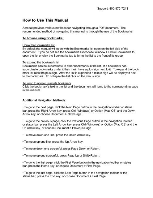
How to Use This <strong>Manual</strong><br />
Acrobat provides various methods for navigating through a PDF document. The<br />
recommended method of navigating this manual is through the use of the Bookmarks.<br />
To browse using Bookmarks:<br />
Show the Bookmarks list.<br />
By default the manual will open with the Bookmarks list open on the left side of the<br />
document. If you do not see the bookmarks list choose Window > Show Bookmarks to<br />
open the list or click the Bookmarks tab to bring the list to the front of its group.<br />
To expand the bookmark list<br />
Bookmarks can be subordinate to other bookmarks in the list. If a bookmark has<br />
subordinate bookmarks under it then it will have a plus sign next to it. To expand the book<br />
mark list click the plus sign. After the list is expanded a minus sign will be displayed next<br />
to the bookmark. To collapse the list click on the minus sign.<br />
To jump to a topic using its bookmark<br />
Click the bookmark’s text in the list and the document will jump to the corresponding page<br />
in the manual.<br />
Additional Navigation Methods:<br />
• To go to the next page, click the Next Page button in the navigation toolbar or status<br />
bar, press the Right Arrow key, press Ctrl (Windows) or Option (Mac OS) and the Down<br />
Arrow key, or choose Document > Next Page.<br />
• To go to the previous page, click the Previous Page button in the navigation toolbar<br />
or status bar, press the Left Arrow key, press Ctrl (Windows) or Option (Mac OS) and the<br />
Up Arrow key, or choose Document > Previous Page.<br />
• To move down one line, press the Down Arrow key.<br />
• To move up one line, press the Up Arrow key.<br />
• To move down one screenful, press Page Down or Return.<br />
• To move up one screenful, press Page Up or Shift+Return.<br />
• To go to the first page, click the First Page button in the navigation toolbar or status<br />
bar, press the Home key, or choose Document > First Page.<br />
• To go to the last page, click the Last Page button in the navigation toolbar or the<br />
status bar, press the End key, or choose Document > Last Page.
Accu-Setter II User’s <strong>Manual</strong><br />
GAGES<br />
Edmunds
Table of <strong>Co</strong>ntents<br />
Preface<br />
<strong>Manual</strong> Revision History<br />
Trademark Information<br />
i<br />
i<br />
Introduction<br />
Summary & Features 1-1<br />
Document <strong>Co</strong>nventions 1-2<br />
Anti-Static Precautions 1-2<br />
Glossary of Terms 1-3<br />
Quick Start Guide 1-6<br />
Programming Reference Guide 1-7<br />
System Description<br />
Number References 2-1<br />
Specifications 2-2<br />
Spare Parts 2-2<br />
Overall Unit 2-3<br />
Front Panel 2-4<br />
Rear Panel 2-6<br />
Rear Panel Pin Assignments 2-8<br />
Input/Output Pin Assignments 2-8<br />
RS-232C 2-10<br />
E9310, (2) Channel LVDT Signal <strong>Co</strong>nditioning Module 2-11<br />
E9320, (4) Channel LVDT Signal <strong>Co</strong>nditioning Module 2-12<br />
E9330, (1) Channel A/E Signal <strong>Co</strong>nditioning Module 2-13<br />
E9340, (2) Channel A/E Signal <strong>Co</strong>nditioning Module 2-14<br />
Filter Regulator Assembly 2-15<br />
Basic Operation<br />
Setup & Operation Summary 3-1<br />
Unpacking & Setting Up 3-2<br />
Single Unit Setup 3-2<br />
Multiple Unit Setup 3-5<br />
Signal <strong>Co</strong>nditioning Module Setup 3-6<br />
Signal <strong>Co</strong>nditioning Module Auto Recognition 3-6<br />
Programming 3-7<br />
Programming Guide 3-9<br />
Gaging Formulas 3-10<br />
Single Check Programming 3-15<br />
Multiple Check Programming 3-22<br />
Multiple Fixture Programming 3-31<br />
System Programming 3-39<br />
Inputs Setup 3-45<br />
Setting A/E Mag & Zero 3-45<br />
Setting LVDTs 3-47
Calibration 3-48<br />
Single Check 3-48<br />
Multiple Check 3-50<br />
Multiple Fixture 3-52<br />
Gage Operation 3-54<br />
Single Check Measurement 3-54<br />
Multiple Check or Multiple Fixture Measurement 3-56<br />
Offloading Gage Results 3-58<br />
Advanced Operation<br />
A/E Module Setup 4-1<br />
Output Jumpers 4-2<br />
Module Installation 4-3<br />
A/E Maintenance 4-4<br />
LVDT Module Setup 4-6<br />
Jumper Settings 4-7<br />
Inputs/Outputs 4-7<br />
Attenuation 4-9<br />
Module Installation 4-10<br />
Obsolete Signal <strong>Co</strong>nditioning Modules 4-11<br />
External Device <strong>Co</strong>mmunication 4-12<br />
RS232 4-12<br />
Input/Output Board 4-22<br />
Description 4-22<br />
Typical I/O connections 4-23<br />
Auto Air Shutoff (Optional) 4-25<br />
Troubleshooting 4-28<br />
Index 5-1<br />
Warranty Information 6-1<br />
Service & Support Information 6-1
Table of Figures<br />
Figure 1.1 - Programming Reference Guide 1-7<br />
Figure 2.1 - Overall Basic unit 2-3<br />
Figure 2.2 - Front Panel 2-5<br />
Figure 2.3 - Rear Panel 2-7<br />
Figure 2.4 - I/O Pins 2-8<br />
Figure 2.5 - I/O <strong>Co</strong>nnections 2-9<br />
Figure 2.6 - RS232C Pins 2-10<br />
Figure 2.7 - E9310, (2) Ch. LVDT Module 2-11<br />
Figure 2.8 - E9320, (4) Ch. LVDT Module 2-12<br />
Figure 2.9 - E9330, (1) Ch. A/E Module 2-13<br />
Figure 2.10 - E9340, (2) Ch. A/E Module 2-14<br />
Figure 2.11 - Supply Air Filter/Regulator 2-15<br />
Figure 3.1 - Base Feet 3-3<br />
Figure 3.2 - Filter Regulator Mounting 3-3<br />
Figure 3.3 - Air <strong>Co</strong>nnections 3-4<br />
Figure 4.1 - A/E Modules, E9330 & E9340 4-1<br />
Figure 4.2 - Output Pin Jumpers 4-2<br />
Figure 4.3 - A/E Block 4-5<br />
Figure 4.4 - LVDT Modules, E9310 & E9320 4-6<br />
Figure 4.5 - I/O Jumpers 4-8<br />
Figure 4.6 - Attenuation Jumpers 4-9<br />
Figure 4.7 - RS232C Pins 4-12<br />
Figure 4.8 - Typical I/O <strong>Co</strong>nnections 4-23
Preface<br />
<strong>Manual</strong> Revision History<br />
Revision Change Date<br />
0 Original Issue 6/3/04<br />
Trademark Information<br />
“<strong>Accusetter</strong>” is a registered trademark of Edmunds Gages<br />
i
Introduction<br />
1.0 Summary and Features<br />
The Edmunds Gages <strong>Accusetter</strong> II offers many sophisticated features and benefits for<br />
durable and robust shop floor operation.<br />
The <strong>Accusetter</strong> II is a microprocessor based gaging column that combines a 101 discrete<br />
tri-color LED bargraph display for easy visual monitoring of dimensional measurement<br />
characteristics, with an eight digit alpha numeric display for precise size readings and<br />
operator prompting messages. Illuminated range indicators identify which of the eight<br />
inch or eight millimeter ranges have been selected. The tri-color LED bargraph conveys<br />
both measurement size and status. A single rotary entry switch and six dedicated<br />
pushbuttons provide all of the operator control functions.<br />
The unit is housed in a heavy duty reinforced aluminum case with a module bay for<br />
interchangeable plug in modules which will accommodate Edmunds LVDT type gaging<br />
probes or Edmunds and nearly all major brands of air tooling. The rear panel of the<br />
column contains two female DB25 connectors which provide 6 channels for input/output<br />
bussing of analog signals. These connectors also provide various control/status signals<br />
for the I/O accessory board. An RS-232C connector allows output of gage results to a<br />
data collector. The <strong>Accusetter</strong> II will operate at any supply line voltage between 100<br />
VAC to 240 VAC at either 50 or 60 HZ. An additional receptacle is provided for power<br />
jumper cord connections for multiple column applications. The serial number with<br />
revision letter is identified at the top of the rear panel of the <strong>Accusetter</strong> II.<br />
The <strong>Accusetter</strong> II’s powerful microprocessor allows the user tremendous flexibility in<br />
tailoring the column to match the gaging requirement. Each dimension can be<br />
functionally displayed as a deviation from nominal, absolute size, +peak, -peak, TIR or<br />
class functions. The automatic mastering provides precise calibration without the usual<br />
need of precisely adjusting trim pots and knobs. The user is provided with three distinct<br />
application gaging programs to choose from. The single check program simplifies the<br />
operation of the <strong>Accusetter</strong> II to allow only a single check measurement. The multiple<br />
check program is <strong>Accusetter</strong> II’s unique “4 in 1” feature that allows the user to configure<br />
up to four dimensional checks to be gaged simultaneously in one column. In the multiple<br />
fixture program, an enhanced single check measurement is available for up to four<br />
separate gages. Whenever power is first turned on to the <strong>Accusetter</strong> II, the display will<br />
scroll the software version and the present application program and the module ID.<br />
1-1
1.1 Document <strong>Co</strong>nventions<br />
RUN = Shortcut Programming Key<br />
“INCH” = Alphanumeric Display<br />
1.2 Anti-Static Precautions<br />
When working inside the <strong>Accusetter</strong> II cabinet or handling signal conditioning modules<br />
use caution to protect against damage from static electricity. Use of an anti-static wrist<br />
band or other grounding procedures are recommended.<br />
Power to the column must be turned off prior to installing or removing a signal<br />
conditioning module.<br />
1-2
1.3 Glossary of Terms<br />
Absolute displays the check size as the actual part size.<br />
An A/E (Air to Electric) transducer converts changes in pneumatic pressure into an<br />
electrical signal.<br />
+APPROACH (or -APPROACH) are optional user defined programmable values<br />
approaching the max and min part limits.<br />
AVG (Average) is a function that returns the average check reading.<br />
Bypass is a function that displays a live input reading<br />
A part Check is an input or combination of inputs expressed with a gaging mode to<br />
exhibit a part characteristic.<br />
Calibration is a procedure used to automatically set the magnification and zero shift for<br />
a check by comparing actual gage readings to known certified sizes of a master or<br />
masters.<br />
Deviation displays how much a check size deviates from the nominal size as a variation.<br />
A gaging Formula allows the user to add, subtract, multiply, or divide inputs from<br />
transducers A, B, C, and D.<br />
A Function defines how an input or check will be displayed on the readout. Function<br />
options are Bypass, Average, +Peak, -Peak, TIR, and TOL Check.<br />
The Gain setting on the A/E signal conditioning module sets the amplification factor of<br />
an input signal to a usable value that can be interpreted by the readout device<br />
A Gage is a mechanical device used to measure part characteristics.<br />
Gage Readings are the input values obtained during the gage cycle.<br />
A High Level Signal is an amplified +/-2.5VDC signal that reflects the number of bars<br />
illuminated on the bargraph display.<br />
An Input is the assigned name given to a signal that is to be utilized in a gaging formula.<br />
In LIVE RDG (Live Reading) mode the input signal is directly displayed on the<br />
alphanumeric and bargraph displays in real time.<br />
A Low Level Signal is the raw unamplified voltage from an LVDT or A/E transducer.<br />
1-3
An LVDT (Linear Variable Differential Transformer) is an electromechanical<br />
transducer that converts the linear motion of its contact tip to an AC voltage which can be<br />
interpreted by a readout device.<br />
Magnification is the enlargement of an input signal to a usable value that can be<br />
interpreted by the readout device.<br />
A Maximum (MAX) Master is a precision replica of the gaged part manufactured to the<br />
upper specification limit of the part features, inspected and certified to size, for use in the<br />
calibration of the gage.<br />
A Minimum (MIN) Master is a precision replica of the gaged part manufactured to the<br />
lower specification limit of the part features, inspected and certified to size, for use in the<br />
calibration of the gage.<br />
A Multiple Check Program allows the user to program up to four dimensional checks to<br />
be gaged simultaneously in one column. All checks must use the same range.<br />
A Multiple Fixture Program allows the user to program the <strong>Accusetter</strong> II with up to<br />
four separate gages each consisting of a single check. The gages can use different ranges.<br />
A Multiplier is part of the check formula. The input reading is multiplied by the this<br />
factor. It is determined by the number of probes used to perform the measurement or to<br />
correct any ratio that may be introduced by any contact arms or tooling.<br />
Polarity is the signed value (+ or -) applied to the magnification of an input to determine<br />
the direction of the input value change.<br />
In +PEAK (or -PEAK) modes the largest (or smallest) size reading since the last reset is<br />
displayed.<br />
Range is the full scale value of the bargraph display.<br />
An R & R is a statistical study performed on a gage to determine the gages repeatability<br />
and reproducibility.<br />
Repeatability is the measurement variation of a gage when used by one operator or<br />
under one set of environmental conditions.<br />
Reproducibility is the variation in measurement averages of a gage when used by more<br />
than one operator or under varying environmental conditions.<br />
The Resolution of a gage is the smallest significant digit of the measurement data that is<br />
displayed.<br />
In Run Mode the user can perform the actual part measurements.<br />
1-4
A Signal <strong>Co</strong>nditioner is a circuit board that modulates and amplifies the LVDT or A/E<br />
signal used by the readout device.<br />
A Single Check Program allows the user to program the <strong>Accusetter</strong> II for one<br />
dimensional check.<br />
In Setup Mode the user can program the required variables for the par checks and<br />
transducers.<br />
In TIR (Total Indicator Reading) mode the difference between the largest and smallest<br />
readings measured is displayed.<br />
TOL Check is a check function that displays the average reading measured when the<br />
check is within the programmed tolerance limits and displays the +Peak or -Peak<br />
readings when the check result is outside the programmed tolerance limits.<br />
A Zero (or Mean) Master is a precision replica of the gaged part manufactured to the<br />
nominal dimensions of the part features and calibrated to size for use in the calibration of<br />
the gage.<br />
A Zero adjustment knob allows operator to drive the displayed readout value to a<br />
desired setting within a limited range.<br />
1-5
1.4 Quick Start Guide<br />
The following steps must be taken to prepare the <strong>Accusetter</strong> II for operation.<br />
1) Unpack and setup the unit.<br />
• Rotate the front foot 90° from its shipping position.<br />
• For air gaging applications, rotate the rear foot 180° from its shipping position and<br />
install the filter regulator assembly. <strong>Co</strong>nnect 60 psi min supply air to the filter<br />
regulator assembly<br />
Note: See "Basic Operations, Unpacking & Setup" for additional information, page 3-1<br />
2) Setup and install the signal conditioning module if it was not installed before<br />
shipment and connect the gage tooling.<br />
Power to the column must be turned off prior to installing or removing a signal<br />
conditioning module.<br />
• Check that the jumpers and switches on the LVDT or A/E signal conditioning board<br />
to be used are properly setup for the application to be run.<br />
• Install the signal conditioning module into the lower bay and secure with the two<br />
thumb screws on the front panel.<br />
• Plug in the LVDT(s) or airline from the gaging fixture to the signal conditioning<br />
module.<br />
Note: See the "Advanced Operation, Module Setup" section for additional information,<br />
page 4-1.<br />
3) Program <strong>Accusetter</strong> II for the application.<br />
• Plug the power cord into the rear of the unit and to a 100 VAC to 240 VAC 50/60 Hz<br />
power supply. Turn the unit on using the on/off switch on the rear of the unit.<br />
• Using the programming keys and the enter button program the variables such as<br />
range, scale, and limits for the application.<br />
Note: See the "Basic Operation, Programming" for additional information, page 3-7<br />
4) Set up magnification and zero for the air inputs.<br />
• Using the masters for the gage tooling and the mag and zero adjustments on the signal<br />
conditioning module setup the air input(s).<br />
Note: See "Basic Operation, Input Setup" for additional information, page 3-40<br />
5) Master the gage using Calibration mode.<br />
Note: See "Basic Operation, Calibration" for additional information, page 3-43<br />
6) Select Run mode and the unit is ready for gaging.<br />
1-6
Programming Reference Guide<br />
The following reference guide briefly outlines the functions of the programming buttons<br />
for the <strong>Accusetter</strong> II.<br />
Figure 1.1<br />
Note: RANGE shortcut key is inactive for air applications.<br />
NOTE: If the RANGE is changed the master sizes and part limits must also<br />
be reprogrammed.<br />
1-7
System Description<br />
2.0 Number References<br />
<strong>Co</strong>mponent<br />
Edmunds Gages Number<br />
Basic <strong>Accusetter</strong> II Unit<br />
E9300<br />
(2) Channel LVDT Signal <strong>Co</strong>nditioning Module E9310<br />
(4) Channel LVDT Signal <strong>Co</strong>nditioning Module E9320<br />
(1) Channel A/E Signal <strong>Co</strong>nditioning Module E9330<br />
(2) Channel A/E Signal <strong>Co</strong>nditioning Module E9340<br />
Power Cable 4550111<br />
Air Filter/Regulator Assembly 5801302<br />
Interface Cable 4550200<br />
Printer Cable 5809060<br />
Power Jumper Cable 4550120<br />
I/O Accessory Board 5911013<br />
Send Data Foot Switch* 5911100<br />
TIR Reset Foot Switch* 5911101<br />
Auto Air Shutoff Kit (Optional) 5913250<br />
Includes: Valve Assembly 5911200<br />
Shutoff Cable* 5911018<br />
*Note: Foot switch and air shutoff cables must be plugged into the "In/Out B" port.<br />
A new <strong>Accusetter</strong> II will be supplied with an E9310, E9320, E9330, or E9340 signal<br />
conditioning module, however the <strong>Accusetter</strong> II is compatible with the obsolete<br />
signal conditioning modules listed below:<br />
Obsolete Signal <strong>Co</strong>nditioning Modules<br />
Edmunds Gages Number<br />
(2) Channel LVDT Signal <strong>Co</strong>nditioning Module E9010<br />
(4) Channel LVDT Signal <strong>Co</strong>nditioning Module E9020<br />
(1) Channel A/E Signal <strong>Co</strong>nditioning Module E9030<br />
(1) Channel A/E Signal <strong>Co</strong>nditioning Module E9031<br />
(2) Channel A/E Signal <strong>Co</strong>nditioning Module E9040<br />
(2) Channel A/E Signal <strong>Co</strong>nditioning Module E9041<br />
Power to the column must be turned off prior to installing or removing a signal<br />
conditioning module.<br />
2-1
2.1 Specifications<br />
Overall Dimensions 21.25” x 2.50” x 9.00”<br />
Power Requirements<br />
100 VAC to 240 VAC 50/60 Hz<br />
Power <strong>Co</strong>nsumption<br />
12 Watts @ 120 VAC, 100 mA<br />
Air Requirements (E9330 or E9340 Module Only)<br />
Pressure<br />
60 psi<br />
Flow Rate<br />
1.6 scfm/air tooling nozzle<br />
Environmental Operating <strong>Co</strong>nditions<br />
Max Temperature<br />
50°C/120°F<br />
2.2 Recommended Spare Parts<br />
Below is a list of recommended spare parts for the <strong>Accusetter</strong> II. These items may be<br />
ordered separately from Edmunds Gages, they are not included with the basic unit.<br />
Part Edmunds Gages P/N Qty.<br />
Basic Unit<br />
10 Amp Fuse 4190135 2<br />
Limit Pointer Assembly 5809508-BM 2<br />
E9310 & E9320 LVDT Modules<br />
2 Position Shunt, .100 Spacing 4570117 1<br />
E9330, (1) Ch. A/E Module<br />
A/E Block 3101500 1<br />
Needle Valve Assembly 3101045 1<br />
O-Ring, Restriction Screw 5900026 1<br />
O-Ring, Body 5900027 1<br />
Bias Restrictor Assembly 3101188-B 1<br />
Filter Disc 3101130-B 2<br />
Bias Restrictor O-Ring 5900026 2<br />
Transducer O-Ring 5900043 2<br />
Air Filter Replacement Element SMC #KT-AF2000-5B 1<br />
2 Position Shunt, .100 Spacing 4570117 1<br />
E9340, (2) Ch. A/E Module<br />
A/E Block 3101510 1<br />
Needle Valve Assembly 3101045 2<br />
O-Ring, Restriction Screw 5900026 2<br />
O-Ring, Body 5900027 2<br />
Bias Restrictor Assembly 3101188-B 1<br />
Filter Disc 3101130-B 2<br />
Bias Restrictor O-Ring 5900026 2<br />
Transducer O-Ring 5900043 4<br />
Air Filter Replacement Element SMC #KT-AF2000-5B 1<br />
2 Position Shunt, .100 Spacing 4570117 1<br />
2-2
2.3 Overall E9300Unit<br />
Figure 2.1 - <strong>Accusetter</strong> II Basic Unit - E9300<br />
2-3
2.4 Front Panel<br />
The <strong>Accusetter</strong> II front panel consists of the following items:<br />
Bargraph display - The 10 inch, 101 point, three color LED bargraph display is the<br />
primary readout for the <strong>Accusetter</strong> II. When over and under limits are programmed, the<br />
bargraph will change colors to visually indicate over or under (red), approaching part<br />
limits (yellow), or good parts (green).<br />
Range Annunciators - Located next to the bargraph, the half scale indicators display the<br />
bargraph values for the various ranges.<br />
Adjustable Limit Pointers - Mechanically positioned limit indicators.<br />
Range Indicator - Displays the currently selected full scale range. Inch ranges are<br />
displayed in green. Metric ranges are displayed in amber.<br />
Range Options:<br />
Inch Metric<br />
.0002" .005mm<br />
.0005" .01mm<br />
.001" .02mm<br />
.002" .05mm<br />
.005" .10mm<br />
.010" .20mm<br />
.020" .50mm<br />
.050" 1.00mm<br />
Alphanumeric Display - During gaging operation the alphanumeric display provides a<br />
digital readout of the bargraph value. During programming the alphanumeric display<br />
shows information on the current programming selections.<br />
Programming Keys - Provide a shortcut to the various programmable options.<br />
Rotary Enter Button - The enter button can be either pressed or rotated and is used<br />
during the programming of the <strong>Accusetter</strong> II.<br />
2-4
Figure 2.2 - Front Panel<br />
2-5
2.5 Rear Panel<br />
The <strong>Accusetter</strong> II rear panel contains the following items:<br />
Serial Number - The Edmunds Gages serial number is listed at the top of the rear panel.<br />
Fuse Locator - <strong>Co</strong>ntains a 10 Amp fuse.<br />
Power Switch - Use to switch the unit on or off.<br />
Power <strong>Co</strong>nnector - Plug the power cable (Edmunds #4550111) into the power connector<br />
and connect to input line voltage from 100 to 240 VAC at 50 or 60 Hz. The <strong>Accusetter</strong><br />
II contains a universal power supply that will automatically adjust to any line voltage in<br />
the above range.<br />
Power Outlet Jumper - In a multiple <strong>Accusetter</strong> II setup, plug power jumper cables<br />
(Edmunds #4550120) from the power outlet jumper on one unit to the power connector<br />
on the next unit.<br />
RS-232C <strong>Co</strong>nnector - Use to output gage results to an external data collector.<br />
IN/OUT A (25 Pin) - Use to input/output parallel and analog signals from another<br />
<strong>Accusetter</strong> II or to an external device using interface cable, Edmunds #4550203. See<br />
figure 2-3 for pin assignments.<br />
IN/OUT B (25 Pin) - Use to input/output parallel and analog signals from another<br />
<strong>Accusetter</strong> II or to an external device using interface cable, Edmunds #4550203. See<br />
figure 2-3 for pin assignments.<br />
44 PSI Inlet - When the air to electric module is installed in the lower bay, an air hose<br />
fitting will extend out the 44 psi inlet port on the rear of the <strong>Accusetter</strong> II. An air line is<br />
connected to this fitting and to the outlet side of the air filter/regulator assembly.<br />
2-6
Figure 2.3 - Rear Panel<br />
2-7
2.6 Pin Assignments for Rear Panel connectors<br />
In/Out A, In/Out B (25 Pin Female DSUB)<br />
Figure 2.4 - I/O Pins<br />
Pin Number IN/OUT A Description IN/OUT B Description<br />
1 Analog Out 1 “<br />
2 Analog Out 2 “<br />
3 Analog Out 3 “<br />
4 Analog Out 4 “<br />
5 Analog Out 5 “<br />
6 Analog Out 6 “<br />
7 Air shut off present (Input) “<br />
8 Spare 1 (Input) “<br />
9 Air off (Output) “<br />
10 Spare 2 (Output) “<br />
11 AGND “<br />
12 Over Relay/Class Bit 0 (Output) “<br />
13 Good Relay/Class Bit 1 (Output) “<br />
14 Under Relay/Class Bit 2 (Output) “<br />
15 Hold (Input) “<br />
16 Status/Class Request (Input) “<br />
17 Footswitch (Send Data/Input) “<br />
18 NC +V (External Switch)<br />
19 Relay Output <strong>Co</strong>mmon “<br />
20 TIR Reset (Input) “<br />
21 +Approach/Class Bit 3 (Output) “<br />
22 -Approach/Class Bit 4 (Output) “<br />
23 Class Bit 5 (Output) “<br />
24 Isolated <strong>Co</strong>mmon “<br />
25 NC High Level Analog Out<br />
• NC = Not connected<br />
2-8
Typical IO <strong>Co</strong>nnections - I/O Board #5911013<br />
OUTPUT "SINKING"<br />
IO A/B<br />
IO A/B<br />
P13<br />
LOAD<br />
+24 VDC (+)<br />
LOAD<br />
P13<br />
CURRENT<br />
FLOW<br />
GOOD<br />
RELAY<br />
P19<br />
0 VDC (-)<br />
P19<br />
-<br />
24VDC<br />
Power Supply<br />
+<br />
OUTPUT "SOURCING"<br />
IO A/B<br />
IO A/B<br />
P13<br />
LOAD<br />
+24 VDC (+)<br />
P19<br />
CURRENT<br />
FLOW<br />
GOOD<br />
RELAY<br />
P19<br />
0 VDC (-)<br />
LOAD<br />
P13<br />
+<br />
24VDC<br />
Power Supply<br />
-<br />
Figure 2.5<br />
2-9
RS232C (9 Pin Female DSUB)<br />
Figure 2.6 - RS-232C Pins<br />
<strong>Accusetter</strong> II Cable External Device<br />
Pin 1 = Chassis Ground. ß----------------------------à Chassis Ground.<br />
Pin 2 = Receive (RXD) ß----------------------------à (TXD) Transmit.<br />
Pin 3 = Transmit (TXD) ß----------------------------à (RXD) Receive.<br />
Pin 5 = Signal Ground ß----------------------------à Signal Ground.<br />
Note: Pin2 and 3 are jumper selectable based upon the application.<br />
2-10
2.7 E9310 (2) Channel LVDT Signal <strong>Co</strong>nditioning Module<br />
The E9310 module is a two-channel signal conditioning amplifier for inductive type<br />
transducers such as LVDTs that converts the outputs of the transducers into a conditioned<br />
signal for the main controller board. The module is mounted in the lower bay of the<br />
<strong>Accusetter</strong> II.<br />
Input magnification must be set using jumpers allowing magnification reduction to be set<br />
to 10x for long range transducers or 1x for standard transducers.<br />
A jumper matrix on the board allows it to accept signals in or send signals out to the<br />
analog output connector. By placing the jumper pin for the desired signal line on one of<br />
the six buss lines, the signal can now be sent or received by any other units connected to<br />
the buss.<br />
Power to the column must be turned off prior to installing or removing a signal<br />
conditioning module.<br />
Refer to the Advanced Operation, LVDT Module Setup section for additional<br />
information on jumper settings.<br />
Figure 2.7 - E9310 (2) Channel LVDT Signal <strong>Co</strong>nditioning Module<br />
2-11
2.8 E9320 (4) Channel LVDT Signal <strong>Co</strong>nditioning Module<br />
The E9320 module is a four-channel signal conditioning amplifier for inductive type<br />
transducers such as LVDTs that converts the outputs of the transducers into a conditioned<br />
signal for the main controller board. The module is mounted in the lower bay of the<br />
<strong>Accusetter</strong> II.<br />
Input magnification must be set using jumpers allowing magnification reduction to be set<br />
to 10x for long range transducers or 1x for standard transducers.<br />
A jumper matrix on the board allows it to accept signals in or send signals out to the<br />
analog output connector. By placing the jumper pin for the desired signal line on one of<br />
the six buss lines, the signal can now be sent or received by any other units connected to<br />
the buss.<br />
Power to the column must be turned off prior to installing or removing a signal<br />
conditioning module.<br />
Refer to the Advanced Operation, LVDT Module Setup section for additional<br />
information on jumper settings.<br />
Figure 2.8 - E9320 (4) Channel LVDT Signal <strong>Co</strong>nditioning Module<br />
2-12
2.9 E9330 (1) Channel A/E Signal <strong>Co</strong>nditioning Module<br />
The E9330 module is a single channel air/electric amplifier which processes pneumatic<br />
information from the air tooling and delivers a conditioned signal to the controller board<br />
of the <strong>Accusetter</strong> II. The module is mounted in the lower bay of the <strong>Accusetter</strong> II.<br />
The A/E module also contains a ZERO adjustment knob and a MAG adjustment knob for<br />
initial input setup to accommodate the air tooling used..<br />
The air tooling is connected to the air fitting on the front panel of the module. The<br />
recommended length of air line from the module to the air tool is no more than six feet.<br />
A minimum of 60 psi air must be supplied to the filter/regulator assembly on the rear of<br />
the unit. The regulator is factory set to 44 psi.<br />
A jumper strip labeled "A OUT" provides the option to select a pin, 1 -6, to output a high<br />
level (+/-1.84VDC) signal to the I/O connectors.<br />
Power to the column must be turned off prior to installing or removing a signal<br />
conditioning module.<br />
Refer to the Advanced Operation, A/E Module Setup section for additional<br />
information on jumper settings and see Basic Operation, Setting A/E Mag & Zero<br />
for additional information on setting Mag and Zero for a particular application.<br />
Figure 2.9 - E9330 (1) Channel AE Signal <strong>Co</strong>nditioning Module<br />
2-13
2.10 E9340 (2) Channel A/E Signal <strong>Co</strong>nditioning Module<br />
The E9340 module is a two channel air/electric amplifier which processes pneumatic<br />
information from the air tooling and delivers a conditioned signal to the controller board<br />
of the <strong>Accusetter</strong> II. The module is mounted in the lower bay of the <strong>Accusetter</strong> II<br />
The A/E module also contains a ZERO adjustment knob and a MAG adjustment knob for<br />
each input for initial input setup to accommodate the air tooling used..<br />
The air tooling is connected to the air fitting on the front panel of the module. The<br />
recommended length of air line from the module to the air tool is no more than six feet.<br />
A minimum of 60 psi air must be supplied to the filter/regulator assembly on the rear of<br />
the unit. The regulator is factory set to 44 psi.<br />
A jumper strip labeled "A OUT" and "B OUT" provides the option to select a pin, 1 -6,<br />
to output a high level (+/-1.84VDC) signal(s) to the I/O connectors.<br />
Power to the column must be turned off prior to installing or removing a signal<br />
conditioning module.<br />
Refer to the Advanced Operation, A/E Module Setup section for additional<br />
information on jumper settings and see Basic Operation, Setting A/E Mag & Zero<br />
for additional information on setting Mag and Zero for a particular application.<br />
Figure 2.10 - E9340 (2) Channel AE Signal <strong>Co</strong>nditioning Module<br />
2-14
2.11 Supply Air Filter/Regulator Assembly<br />
Any unit supplied with an A/E signal conditioning module will also be supplied with a<br />
filter/regulator assembly. The assembly is mounted to the rear foot of the <strong>Accusetter</strong> II.<br />
The regulator is factory preset to 44psi and requires a clean, dry air supply at 60psi min.<br />
The regulator output is connected to a fitting on the A/E module that extends out of the<br />
44psi inlet port on the rear panel of the <strong>Accusetter</strong> II.<br />
Figure 2.11 - Supply Air Filter/Regulator<br />
2-15
Basic Operation<br />
3.0 Set up and Operation Summary<br />
The following steps must be taken to prepare the <strong>Accusetter</strong> II for operation.<br />
1) Unpack and setup the unit. See "Unpacking & Setup" below.<br />
2) Setup signal conditioning module jumpers and install module. See the "Advanced<br />
Operation" section.<br />
Power to the column must be turned off prior to installing or removing a signal<br />
conditioning module.<br />
3) Program <strong>Accusetter</strong> II for the application. See the "Programming" section below.<br />
4) Set up magnification and zero for the air gage input or inputs. See "Input Setup" below<br />
or set up the LVDT probes. See "Input Setup" below.<br />
5) Calibrate the gage(s). See "Calibration".<br />
6) Select Run mode and unit is ready for gaging. See "Operation".<br />
3-1
3.1 Unpacking & Setting Up<br />
Unpacking<br />
Ensure that the following items are received when the unit is unpacked:<br />
• Basic <strong>Accusetter</strong> II unit (E9300)<br />
• Signal <strong>Co</strong>nditioning Module (E9310 or E9320 air module or E9330 or E9340 electronic<br />
module)<br />
• Power Cable #4550111<br />
• Filter/Regulator (for air gaging modules E9310 or E9320 only) #5801302<br />
• Hose Assembly (for air gaging modules E9310 or E9320 only) #3101053-B<br />
Setup<br />
The <strong>Accusetter</strong> II can be used as a stand alone unit or as part of a multiple <strong>Accusetter</strong> II<br />
setup.<br />
Single <strong>Accusetter</strong> II Setup<br />
1) Turn the <strong>Accusetter</strong> II upside down and remove the front foot mounting screw.<br />
2) Rotate the front foot 90° from its shipping position so that it is perpendicular to the<br />
column and remount as shown below.<br />
3) If air gaging is to be used, remove the two mounting screws for the rear mounting<br />
bracket and rotate the rear foot 180° from its shipping position so that the air<br />
filter/regulator assembly can be mounted as shown in figure 3.1.<br />
4) Turn the unit right side up.<br />
5) For air gaging applications only, attach the air line from the filter/regulator assembly to<br />
the fitting extending from the rear of the column.<br />
6) Ensure the power switch on the rear of the column is turned “OFF”.<br />
7) Plug the power cord into the male electrical receptacle on the rear of the column.<br />
8) Plug the power cord into a power source between 100VAC and 240VAC at 50 or 60<br />
Hz.<br />
9) For air gaging applications only, connect a source of clean, dry air at 60 psi min to the<br />
air filter/regulator inlet. NOTE: The <strong>Accusetter</strong> II regulator is factory set to 44psi.<br />
10) <strong>Co</strong>nnect the gage tooling to be used to the signal conditioning module. For air gaging<br />
connect the air hose from the air plug, air ring, or air snap to the tooling port on the<br />
front of the A/E module. For electronic gaging connect the one or two LVDTs to<br />
inputs A and/or B on the front of the LVDT module.<br />
11) Turn on the <strong>Accusetter</strong> IIby turning the power switch on the rear of the unit to “ON”.<br />
3-2
Rear Mounting Bracket<br />
Front Mounting Foot<br />
Figure 3.1 - Base Feet<br />
Figure 3.2 - Filter/Regulator Mounting<br />
3-3
Figure 3.3 - Air <strong>Co</strong>nnections<br />
For Air Gaging Application Only<br />
3-4
Multiple <strong>Accusetter</strong> II Setup<br />
1) Turn the <strong>Accusetter</strong> II units upside down and remove the front foot mounting screws.<br />
2) Rotate the front foot 90° from its shipping position so that it is perpendicular to the<br />
column and remount as shown above. Up to three columns can be mounted on the<br />
same front foot.<br />
3) If air gaging is to be used, remove the two mounting screws for the rear foot and rotate<br />
the rear foot 180° from its shipping position so that the air filter/regulator assembly can<br />
be mounted as shown below. Repeat for all columns using air gaging.<br />
4) Turn the units right side up.<br />
5) For air gaging applications only, attach the air line from the filter/regulator assembly to<br />
the fitting extending from the rear of the column.<br />
6) Ensure the power switch on the rear of the column is turned “OFF”.<br />
7) Plug the power cord into the male electrical receptacle on the rear of one of the<br />
columns.<br />
8) Plug a power jumper cable (#4550120) from the power outlet on the rear of the column<br />
with the power cord to the male electrical receptacle on the next column. Repeat until<br />
all columns are connected with power jumper cables.<br />
9) Plug the power cord into a power source between 100VAC and 240VAC at 50 or 60<br />
Hz.<br />
10) For air gaging applications only, connect a source of clean, dry air at 60 psi min to all<br />
the air filter/regulator inlets.<br />
11) <strong>Co</strong>nnect the gage tooling to be used to the signal conditioning module. For air gaging<br />
connect the air hose(s) from the air plug, air ring, or air snap to the tooling port(s) on<br />
the front of the A/E module. For electronic gaging connect the LVDTs to the inputs on<br />
the front of the LVDT module.<br />
12) Turn on the <strong>Accusetter</strong> IIby turning the power switches on the rear of the units to<br />
“ON”.<br />
3-5
3.2 Signal <strong>Co</strong>nditioning Module Setup<br />
For LVDT modules E9310 & E9320 attenuation jumpers must be set to either 1x for<br />
standard transducers or 10x for long range transducers. Refer to the "Advanced<br />
Operations" section for additional information.<br />
For either an LVDT or A/E signal conditioning module a jumper matrix on the board<br />
allows it to accept signals in or send signals out to the analog output connector. Refer to the<br />
"Advanced Operations" section of the manual for additional information on setting these<br />
jumpers.<br />
Signal <strong>Co</strong>nditioning Module Auto Recognition<br />
When an E9310, E9320, E9330, or E9340 module is installed in the lower bay the<br />
<strong>Accusetter</strong> II will automatically detect the type of signal conditioning module installed and<br />
certain setup parameters will be programmed automatically based on the jumper settings on<br />
the module. This feature is not available on legacy signal conditioning modules.<br />
For an E9310 or E9320 module the following parameters will be detected:<br />
• Under the "Xducer" menu the Signal <strong>Co</strong>nditioning will be set to "Electric"<br />
• The position of the attenuation jumpers J5-J8 and J10 (1x or 10X) will be detected<br />
For an E9330 or E9340 module the following parameters will be detected:<br />
• Under the "Xducer" menu the Signal <strong>Co</strong>nditioning will be set to "Air"<br />
When the <strong>Accusetter</strong> II is powered on the module ID code of the currently installed module<br />
is displayed in the scroll of start up information. For the LVDT modules E9310 & E9320<br />
the ID code will also identify the status of the "J10" attenuation jumper (1x or 10x).<br />
Module<br />
ID <strong>Co</strong>de<br />
E9010, 20, 30, 40 Legacy Module<br />
FF<br />
(no module recognition)<br />
E9310, Jumper J10 = 1x E1<br />
E9310, Jumper J10 = 10x E2<br />
E9320, Jumper J10 = 1x E3<br />
E9320, Jumper J10 = 10x E4<br />
E9330<br />
E5<br />
E9340<br />
E6<br />
Power to the column must be turned off prior to installing or removing a signal<br />
conditioning module.<br />
3-6
3.3 Programming<br />
Choose The Proper Program For Your Application:<br />
1) Single-check — One feature is to be measured.<br />
2) Multiple check — Up to four features are to be measured using one gage or fixture.<br />
3) Multiple fixture — Up to four different gages may be used.<br />
How To Select The Type Program The First Time:<br />
1) Turn power on with toggle power switch in rear of unit, after the power cord has been<br />
hooked-up.<br />
2) Press RST button while "ACCUSETTER" is scrolling in the LED display.<br />
3) The display will read "CHG PRG?" (change program).<br />
4) Press the enter button and rotate until desired program is displayed, single check<br />
("SNGL CHK"), multiple check ("MPL CHK"), and multiple fixture ("MPL FXT").<br />
5) Press the ENTER button again to select the program you need.<br />
6) <strong>Accusetter</strong> will scroll "PERFORM ACCUSETTER SETUP" or the program<br />
description.<br />
a) If a different program type is being selected from that previously stored,<br />
"PERFORMING ACCUSETTER SETUP" will Scroll until the ENTER button is<br />
pressed. The Accu-Setter will then display "SETUP". <strong>Co</strong>ntinue with programming.<br />
b) If the same type program is being selected, the Accu-Setter software S/N version &<br />
program description will scroll and go automatically into the run mode after a (10)<br />
second delay. If the Accu-Setter displays the type of program you want, but has not<br />
been programmed for your application, you may need to change the program for<br />
your application. To do that, press enter button. The Accu-Setter will display<br />
"SETUP". <strong>Co</strong>ntinue with programming.<br />
3-7
How To Select A Stored Program From Part Database Memory<br />
If a program has already been stored in the memory, and you wish to use it:<br />
1) From Run mode, press the ENTER button and then rotate the ENTER button to display<br />
"PART DB".<br />
NOTE: This menu can also be accessed from the PART DB shortcut key<br />
2) Press the ENTER button.<br />
2) "PART #1" will display.<br />
3) Rotate the ENTER button to display desired part program.<br />
4) Press the ENTER button to select and load.<br />
5) "PART DB" will display.<br />
6) Press the RUN button, "CANCEL" will display.<br />
7) Rotate the ENTER button to display "SAVE".<br />
8) Press the ENTER button to save setup.<br />
9) Proceed to Calibration and Operation sections of this manual.<br />
How To Store A New Program In Part Database Memory<br />
NOTE: Prior to storing, a part name must be programmed for each new program or the<br />
database will store the default name, Part 1, for every program.<br />
NOTE: This operation can not be accessed from the PART DB shortcut key, it must be<br />
accessed through the System menu.<br />
1) From Run mode, press the ENTER button and then rotate the ENTER button to display<br />
"SYSTEM" and then press ENTER.<br />
2) Rotate the ENTER button to display "PART DB".<br />
3) Press the ENTER button. "PART #1" will display. Rotate the ENTER button to select<br />
the desired data base location.<br />
4) Press the ENTER button. "SELECT" will display.<br />
5) Rotate the ENTER button until "SAVE" is displayed and then press the ENTER button.<br />
6) Press the RUN button to return to run mode.<br />
How To Clear a Program In Part Database Memory<br />
NOTE: This operation can not be accessed from the PART DB shortcut key, it must be<br />
accessed through the System menu.<br />
1) From the Run mode, press the ENTER button and then rotate the ENTER button to<br />
display "SYSTEM" and press ENTER.<br />
2) Rotate the ENTER button to display "PART DB".<br />
3) Press the ENTER button. "PART #1" will display. Rotate the ENTER button to select<br />
the program to be cleared.<br />
4) Press the ENTER button. "SELECT" will display.<br />
5) Rotate the ENTER button until "CLEAR" is displayed and then press the ENTER<br />
button.<br />
6) Press the RUN button "CANCEL" will display.<br />
7) Rotate the ENTER button to display "SAVE" and press the ENTER button to confirm<br />
the program deletion.<br />
8) Press the RUN button to return to run mode.<br />
3-8
<strong>Accusetter</strong> II Programming Guide<br />
The <strong>Accusetter</strong> II system programming guide provides a convenient table for recording<br />
programming information.<br />
A brief explanation of the program guide follows:<br />
The top section of the programming guide lists the program type, signal conditioning<br />
information, scale, and input magnification and polarity. Any signals bussed in or out are<br />
also listed.<br />
The next section list the setup information for each check including check name, function,<br />
inputs, and range. The part limits for each check are also listed.<br />
3-9
Gaging Formulas<br />
The gaging formula under FUNCTION on the <strong>Accusetter</strong> II allows the user to add,<br />
subtract, multiply, or divide inputs from transducers A, B, C, and D. The <strong>Accusetter</strong> II<br />
requires a gaging formula for all applications programmed in the Multiple Check and<br />
Multiple Fixture programs.<br />
For air gaging applications, the gaging formula will always be 1.000 for Input A or Input B.<br />
For electronic gaging applications using LVDTs, the gaging formula will be dependent<br />
upon the specific gaging application.<br />
Gaging probes used within any system are strategically mounted to contact the work piece<br />
at specified locations to perform measurements. These probes, or their output values, must<br />
be combined in an algebraic fashion to provide the measurements desired.<br />
There are four elements required to developing a gaging formula. These include:<br />
1. Input definition.<br />
2. Polarity.<br />
3. Multiplier.<br />
4. Gaging Function.<br />
Input definition is simply identifying the probes or “inputs” to the readout that will be used<br />
to measure the part. As an example, let us use two opposing LVDT probes and assume that<br />
these are the first inputs connected to the readout. These will be identified as inputs 1A and<br />
1B.<br />
Polarity must be determined for the application at hand. For example, consider a gage with<br />
two probes measuring an outer diameter, the probe’s normal operation defines the polarity<br />
as (+) when the tip is depressed. Thus the polarity programmed in the <strong>Accusetter</strong> for each<br />
of our inputs for this example will be (+) plus. As the diameter grows, the probes are<br />
depressed providing positive readings indicating a larger part diameter.<br />
Next, we must apply a multiplier to the probes outputs that is dependant on the application.<br />
The multiplier is determined by the number of probes used to perform the measurement or<br />
to correct any ratio that may be introduced by any contact arms or tooling.<br />
3-10
An example of various multipliers as related to diameter measurement follows:<br />
3-11
The last consideration to complete the formula is the gaging function. See examples<br />
below:<br />
3-12
Multiple Check Formulas<br />
If the <strong>Accusetter</strong> is programmed for multiple check operation then the results of checks 1,<br />
2, and/or 3 can be combine algebraically. For an example of a multiple check application<br />
consider and air plug that measures a part ID at two elevations. The large diameter is<br />
measured with input A and displays the large diameter size as check #1. The small<br />
diameter is measured with input B and displays the small diameter size as check #2. To<br />
display the part taper check #3 can be defined as a multiple check to display the results of<br />
check #1 minus check #2.<br />
Check #1, Large Diameter<br />
Function = AVG<br />
Formula = A x (+)1.000<br />
Check #2, Small Diameter<br />
Function = AVG<br />
Formula = B x (+)1.000<br />
Check #3, Multiple Check, Taper<br />
Function = AVG<br />
Formula = CHK1 x (+)1.000 + CHK2 x (-)1.000<br />
3-13
Selecting Full Scale Value<br />
All Edmunds air tooling is marked with the full scale range it was intended to work with.<br />
Since overall range of air tooling is limited, our tooling is designed to operate on one scale<br />
only. Random switching of ranges may affect the performance and linearity of the tooling.<br />
Using tooling manufactured for a type of system other than Edmunds’ back-pressure bleed<br />
system may require trial and error to determine the optimum air amplification choice for<br />
the most stable and linear readings. The following chart may be helpful is selecting the<br />
proper magnifications.<br />
Marked Range Air Amplification<br />
.050” / 1mm Not for air use<br />
.020” / .5mm Not for air use<br />
.010” / .2mm Low<br />
.005” / .1mm Low<br />
.002” / .05mm Medium<br />
.001” / .02mm High<br />
.0005” / .01mm High<br />
.0002” / .005mm High<br />
3-14
PROGRAMMING - SINGLE CHECK MEASUREMENT<br />
3-15
PROGRAMMING - SINGLE CHECK MEASUREMENT<br />
3-16
PROGRAMMING - SINGLE CHECK MEASUREMENT<br />
Programming SETUP Options<br />
1) With the column in RUN mode, Press the ENTER button and then rotate the ENTER<br />
button until "SETUP" is displayed.<br />
2) Press the ENTER button.<br />
3) Rotate the ENTER button to select "XDUCER", "DEFINE" or "PART NAME" and<br />
then press the ENTER button.<br />
XDUCER Menu<br />
Signal <strong>Co</strong>nditioning<br />
(Note: These parameters will be automatically set by module<br />
recognition for E9310, E9320, E9330, or E9340 modules)<br />
1) Rotate the ENTER button until "SIG COND" is displayed and then press<br />
the ENTER button.<br />
2) Rotate the ENTER button to select "AIR" or "ELEC" and then press the<br />
ENTER button.<br />
a) If "ELEC" was selected then rotate the ENTER button to select<br />
"GAIN 1X" or "GAIN 10X" and then press the ENTER button to<br />
return to the Xducer menu.<br />
b) If "AIR" was selected then rotate the ENTER button to select LOW<br />
MAG, MED MAG, or HIGH MAG and then press ENTER to return<br />
to the Xducer menu.<br />
Scale<br />
1) Rotate the ENTER button until "SCALE" is displayed and then press the<br />
ENTER button.<br />
2) Rotate the ENTER button to select "INCH" or "METRIC".<br />
3) Press the ENTER button and the <strong>Accusetter</strong> will return to the Xducer<br />
menu and display "SCALE".<br />
3-17
PROGRAMMING - SINGLE CHECK MEASUREMENT<br />
Pol/Mag<br />
1) Rotate the ENTER button until "POL/MAG" is displayed and then press<br />
the ENTER button.<br />
2) Rotate the ENTER button to select "INPUT A" or "INPUT B" and then<br />
press the ENTER button. A numerical value with a polarity (+ or -)sign<br />
will be displayed.<br />
3) Enter the correct polarity and magnification. Refer to the <strong>Accusetter</strong><br />
program guide supplied with your gage.<br />
4) After setting the polarity and mag for one input press RST and then<br />
rotate the ENTER button to select the next input to be set up. Repeat<br />
steps 2 - 4.<br />
5) After programming all required inputs press RST until "XDUCER" is<br />
displayed. All Xducer options are now programmed.<br />
How To Enter Numerical Values and polarities<br />
Enter the correct numeral or polarity by pressing the enter button to move<br />
from one decimal place to another. To change numbers or polarity signs<br />
rotate the ENTER button left or right until desired number or sign is<br />
displayed.<br />
DEFINE Menu<br />
1) From Run mode press the ENTER button.<br />
2) Rotate the ENTER button to display "SETUP" and then press ENTER.<br />
3) Rotate the ENTER button to display "DEFINE" and then press ENTER.<br />
Function<br />
1) Rotate the ENTER button until "FUNCTION" is displayed and then<br />
press ENTER.<br />
2) Rotate the ENTER button to select from "BYPASS", "+PEAK", "-<br />
PEAK", or "TIR". Refer to the <strong>Accusetter</strong> program guide for the<br />
correct function for a given application.<br />
3) Press the ENTER button and the <strong>Accusetter</strong> will return to the DEFINE<br />
menu and display "FUNCTION".<br />
3-18
PROGRAMMING - SINGLE CHECK MEASUREMENT<br />
Range<br />
1) Rotate the ENTER button until "RANGE" is displayed and then press<br />
ENTER.<br />
2) Rotate the ENTER button until the desired full scale value is displayed<br />
and then press enter. Refer to the <strong>Accusetter</strong> program guide for the<br />
correct range for a given application. NOTE: If the scale option of the<br />
Xducer menu is set to INCH then only inch range options will be listed<br />
and if the scale option of the Xducer menu is set to METRIC only<br />
metric ranges will be listed.<br />
Note: .020”/.500mm or .050”/1.00mm ranges should be used for electronic<br />
applications only.<br />
3) After the desired range is displayed press the ENTER button.<br />
4) Rotate the ENTER button to select "DEVIATION" or "ABSOLUTE"<br />
and then press the ENTER button.<br />
5) If deviation was selected then the <strong>Accusetter</strong> will return to the define<br />
menu and display "RANGE". If Absolute was selected then use the<br />
ENTER button to program the nominal part size. After programming<br />
the nominal size press the RST button until "RANGE" is displayed.<br />
NOTE: If the RANGE is changed the master sizes and part limits must<br />
also be reprogrammed.<br />
Limits<br />
1) Rotate the ENTER button until "LIMITS" is displayed and then press<br />
the ENTER button.<br />
2) Rotate the ENTER button until "MAX" is displayed and then press the<br />
ENTER button.<br />
3) Rotate the ENTER button to drive the bargraph until the max limit is<br />
displayed and press the ENTER button.<br />
4) Rotate the ENTER button until "MIN" is displayed and then press the<br />
ENTER button.<br />
5) Rotate the ENTER button to drive the bargraph until the min limit is<br />
displayed and then press the RST button to display "LIMITS".<br />
3-19
PROGRAMMING - SINGLE CHECK MEASUREMENT<br />
Master<br />
This menu allows the operator to select which masters will be used to<br />
calibrate the gage and to program the correct master values. For example a<br />
two master system uses a MAX and MIN master while a single master<br />
system would use only the ZERO master. The auxiliary (AUX) master is<br />
used to calibrate a TIR check mastered with a single master. Refer to the<br />
<strong>Accusetter</strong> setup guide to determine what master or masters will be used to<br />
calibrate the gage and refer to the master calibration reports for the actual<br />
master values.<br />
1) Rotate the ENTER button until "MASTER" is displayed and then press<br />
the ENTER button.<br />
2) Rotate the ENTER button until "MAX", "MIN", "AUX", or "ZERO" is<br />
displayed and then press enter.<br />
3) Rotate the ENTER button to select "ON" or "OFF" and then press<br />
ENTER.<br />
NOTE: If the auxiliary master ("AUX") is turned "ON" then "MAX" and<br />
"MIN" are automatically turned "OFF" and if "MAX" or "MIN" is turned<br />
"ON" then "AUX" is automatically turned "OFF".<br />
4) If ON was selected then rotate the ENTER button to drive the bargraph<br />
to the master value listed on the master certification report and then<br />
press ENTER and return to step 2. If OFF was selected then return to<br />
step 2.<br />
5) After all required masters are programmed press RST to display<br />
"MASTER".<br />
Check Name<br />
1) Rotate the ENTER button to display "CHK NAME" and then press<br />
ENTER.<br />
2) "PART 1" will display. Press the ENTER button.<br />
3) The first character will flash. Rotate the ENTER button to change the<br />
character and then press ENTER to move to the next character. Press<br />
RST when done. The programmed name will display. Press RST again<br />
to return to the define menu.<br />
Part Names<br />
Note:The part name of the program can be renamed if desired to store in memory.<br />
1) From the Setup menu, rotate the ENTER button to display "PART NAME".<br />
2) Press the ENTER button. "PART 1" will display.<br />
3) Press the ENTER button. The first character will flash. To change, rotate the ENTER<br />
button left or right until desired character is displayed.<br />
4) Press the ENTER button to move to next character.<br />
5) Press the RST button once, when done. The programmed name will display.<br />
6) Press the RST button once.<br />
3-20
PROGRAMMING - SINGLE CHECK MEASUREMENT<br />
Saving the Program<br />
1) Press the RUN button. "CANCEL" will display.<br />
2) Rotate the ENTER button to display "SAVE" and then press the ENTER button to save<br />
the setup.<br />
3-21
PROGRAMMING - MULTIPLE CHECK MEASUREMENT<br />
3-22
PROGRAMMING - MULTIPLE CHECK MEASUREMENT<br />
3-23
PROGRAMMING - MULTIPLE CHECK MEASUREMENT<br />
Multiple Check Programming<br />
Programming SETUP Options<br />
1) With the column in RUN mode, Press the ENTER button and then rotate the ENTER<br />
button until "SETUP" is displayed.<br />
2) Press the ENTER button.<br />
3) Rotate the ENTER button to select "XDUCER", "DEFINE" or "PART NAME" and<br />
then press the ENTER button.<br />
XDUCER Menu<br />
Signal <strong>Co</strong>nditioning<br />
(Note: These parameters will be automatically set by module<br />
recognition for E9310, E9320, E9330, or E9340 modules)<br />
1) Rotate the ENTER button until SIG COND is displayed and then press<br />
the ENTER button.<br />
2) Rotate the ENTER button to select "AIR" or "ELEC" and then press the<br />
ENTER button.<br />
a) If "ELEC" was selected then rotate the ENTER button to select<br />
"GAIN 1X" or "GAIN 10X" and then press the ENTER button to<br />
return to the Xducer menu.<br />
b) If "AIR" was selected then rotate the ENTER button to select LOW<br />
MAG, MED MAG, or HIGH MAG and then press ENTER to return<br />
to the Xducer menu.<br />
Scale<br />
1) Rotate the ENTER button until SCALE is displayed and then press the<br />
ENTER button.<br />
2) Rotate the ENTER button to select "INCH" or "METRIC".<br />
3) Press the ENTER button and the <strong>Accusetter</strong> will return to the Xducer<br />
menu and display "SCALE".<br />
3-24
PROGRAMMING - MULTIPLE CHECK MEASUREMENT<br />
Pol/Mag<br />
1) Rotate the ENTER button until "POL/MAG" is displayed and then press<br />
the ENTER button.<br />
2) Rotate the ENTER button to select "INPUT A", "INPUT B", "INPUT<br />
C", or "INPUT D" and then press the ENTER button. A numerical value<br />
with a polarity (+ or -) sign will be displayed.<br />
3) Enter the correct polarity and magnification. Refer to the <strong>Accusetter</strong><br />
program guide for the correct value and polarity.<br />
4) After setting the polarity and mag for one input press RST and then<br />
rotate the ENTER button to select the next input to be set up. Repeat<br />
steps 2 - 4.<br />
5) After programming all required inputs press RST until XDUCER is<br />
displayed. All Xducer options are now programmed.<br />
How To Enter Numerical Values and polarities<br />
Enter the correct numeral or polarity by pressing the enter button to move from<br />
one decimal place to another. To change numbers or polarity signs rotate the<br />
ENTER button left or right until desired number or sign is displayed.<br />
DEFINE Menu<br />
# CHKS<br />
Use this menu to define the total number of checks to be programmed from 1 to 4.<br />
1) Rotate the ENTER button until "#CHKS" is displayed and then press ENTER.<br />
2) Rotate the ENTER button to select "#CHK=1", "#CHK=2", "#CHK=3", or<br />
"#CHK=4" and then press ENTER to return to the define menu.<br />
3-25
PROGRAMMING - MULTIPLE CHECK MEASUREMENT<br />
CHK 1, CHK 2, CHK 3, CHK 4<br />
Select the check that is to be set up by:<br />
1) Rotate the ENTER button until the desired check number is displayed and then<br />
press ENTER.<br />
2) For each check in the gage setup the FUNCTION, RANGE, LIMITS,<br />
MASTERS, and CHECK NAME per the following instructions.<br />
Function<br />
1) Rotate the ENTER button until "FUNCTION" is displayed and then<br />
press ENTER.<br />
2) Rotate the ENTER button to select from BYPASS, AVG, +PEAK, -<br />
PEAK, TOL CHK, or TIR. Refer to the <strong>Accusetter</strong> program guide for<br />
the correct function for a given application and then press ENTER.<br />
3) Rotate the ENTER button to select FORMULA or MPL CHK and then<br />
press ENTER.<br />
NOTE: Refer to the <strong>Accusetter</strong> setup guide for the gage formula or<br />
multiple check formula to be programmed for this check.<br />
Use the FORMULA menu if the check is a result of one or more gage<br />
inputs and use the MPL CHK formula if this check a combination of the<br />
results from two or more other checks.<br />
Formula<br />
1) Rotate the ENTER button to select input A, B, C, or D and then<br />
press ENTER.<br />
2) A numerical value with a polarity sign (+ or -) will display. Enter<br />
the correct magnification numeral. If this input is not being used,<br />
change number to 0. Enter the correct polarity by pressing the<br />
enter button to move to the + or - position and rotate enter button<br />
to select your choice.<br />
3) Press the RST button to return to the formula menu and rotate<br />
the ENTER button to select the next input, if any, used on the<br />
current check and repeat steps 1 - 2. When all inputs for the<br />
current check have been setup press the RST button until<br />
"FUNCTION" is displayed.<br />
3-26
PROGRAMMING - MULTIPLE CHECK MEASUREMENT<br />
MPL CHK<br />
1) Rotate the ENTER button to select "CHK 1", "CHK 2", or "CHK<br />
3" and then press ENTER.<br />
2) A numerical value with a polarity sign (+ or -) will display. Enter<br />
the correct magnification numeral. If this check is not being<br />
used, change number to 0. Enter the correct polarity by pressing<br />
the enter button to move to the + or - position and rotate enter<br />
button to select your choice.<br />
3) Press the RST button to return to "CHK X" and rotate the<br />
ENTER button to select the next check, if any, used on the<br />
current check and repeat steps 1 - 2. When all check for the<br />
current multiple check have been setup press the RST button<br />
until FUNCTION is displayed.<br />
Range<br />
1) Rotate the ENTER button until "RANGE" is displayed and then press<br />
ENTER.<br />
2) Rotate the ENTER button until the desired full scale value is displayed<br />
and then press enter. Refer to the <strong>Accusetter</strong> program guide for the<br />
correct range for a given application. NOTE: If the scale option of the<br />
Xducer menu is set to INCH then only inch range options will be listed<br />
and if the scale option of the Xducer menu is set to METRIC only<br />
metric ranges will be listed.<br />
Note: .020”/.500mm or .050”/1.00mm ranges should be used for electronic<br />
applications only.<br />
3) After the desired range is displayed press the ENTER button.<br />
4) Rotate the ENTER button to select "DEVIATN" or "ABSOLUTE" and<br />
then press the ENTER button.<br />
5) If "Deviation" was selected then the <strong>Accusetter</strong> will return to the define<br />
menu and display "RANGE". If "Absolute" was selected then use the<br />
ENTER button to program the nominal part size. After programming<br />
the nominal size press the RST button until RANGE is displayed.<br />
NOTE: If the RANGE is changed the master sizes and part limits must<br />
also be reprogrammed.<br />
3-27
PROGRAMMING - MULTIPLE CHECK MEASUREMENT<br />
Limits<br />
MAX, MIN, +APPR, -APPR<br />
1) Rotate the ENTER button until "LIMITS" is displayed and then<br />
press the ENTER button.<br />
2) Rotate the ENTER button until "MAX", "MIN", "+APPR", or" -<br />
APPR" is displayed and then press the ENTER button.<br />
3) Rotate the ENTER button to select whether the limit will be "ON" or<br />
"OFF" and then press ENTER.<br />
4) Rotate the ENTER button to drive the bargraph until the limit value<br />
is displayed and press the ENTER button.<br />
5) Repeat steps 2 - 4 for any limits that are required.<br />
CLASS<br />
1) Rotate the ENTER button until "LIMITS" is displayed and then<br />
press the ENTER button.<br />
2) Rotate the ENTER button until "CLASS" is displayed and then press<br />
ENTER.<br />
3) Rotate the ENTER button to select "EQUAL" or "SELECT" and<br />
then press ENTER.<br />
Note: If you chose "EQUAL", the Accu-Setter will automatically<br />
program the classes after the first class size is programmed. If you<br />
chose SELECT, the operator can program each class size<br />
independently.<br />
4) "QTY" with a numerical value will display. Rotate ENTER button<br />
until desired number of classes is displayed, 39 maximum, and press<br />
the ENTER button.<br />
5) "STRT. PT." will display. Rotate the ENTER button to set the<br />
starting point of first class and then press the ENTER button.<br />
6) "CLASS" with a numerical value will display. Rotate the ENTER<br />
button to set the ending point of the first class and then press the<br />
ENTER button.<br />
7) "CLASS 02" will display if more than one class has been selected.<br />
If EQUAL was selected in step 3 then the <strong>Accusetter</strong> will<br />
automatically program the remaining classes. If SELECT was<br />
chosen in step 3 then rotate the ENTER button to set the ending<br />
point of the next class, press ENTER and repeat until all classes<br />
have been programmed.<br />
8) Press the RST button until "LIMITS" is displayed to return to the<br />
define, checks menu.<br />
3-28
PROGRAMMING - MULTIPLE CHECK MEASUREMENT<br />
Master<br />
This menu allows the operator to select which masters will be used to<br />
calibrate the gage and to program the correct master values. For example a<br />
two master system uses a MAX and MIN master while a single master<br />
system would use only the ZERO master. The auxiliary (AUX) master is<br />
used to calibrate a TIR check mastered with a single master. Refer to the<br />
<strong>Accusetter</strong> setup guide to determine what master or masters will be used to<br />
calibrate the gage and refer to the master calibration reports for the actual<br />
master values.<br />
NOTE: If a check is programmed as a "Multiple Check" then master<br />
values do not need to be programmed and "MASTER" will not appear<br />
as a choice on the check setup menu.<br />
1) Rotate the ENTER button until "MASTER" is displayed and then press<br />
the ENTER button.<br />
2) Rotate the ENTER button until "MAX", "MIN", "AUX", or "ZERO" is<br />
displayed and then press enter.<br />
3) Rotate the ENTER button to select "ON" or "OFF" and then press<br />
ENTER.<br />
NOTE: If the auxiliary master ("AUX") is turned "ON" then "MAX"<br />
and "MIN" are automatically turned "OFF" and if "MAX" or "MIN"<br />
is turned "ON" then "AUX" is automatically turned "OFF".<br />
4) If "ON" was selected then rotate the ENTER button to drive the<br />
bargraph to the master value listed on the master certification report and<br />
then press ENTER and return to step 2. If "OFF" was selected then<br />
return to step 2.<br />
5) After all required masters are programmed press RST to return to the<br />
define menu.<br />
Check Name<br />
1) Rotate the ENTER button to display "CHK NAME" and then press<br />
ENTER.<br />
2) "PART 1" will display. Press the ENTER button.<br />
3) The first character will flash. Rotate the ENTER button to change the<br />
character and then press ENTER to move to the next character. Press<br />
RST when done. The programmed name will display. Press RST again<br />
to return to the define menu.<br />
Part Names<br />
Note:The part name of the program can be renamed if desired to store in memory.<br />
1) From the Setup menu, rotate the ENTER button to display "PART NAME".<br />
2) Press the ENTER button. "PART 1" will display.<br />
3) Press the ENTER button. The first character will flash. To change, rotate the ENTER<br />
button left or right until desired character is displayed.<br />
4) Press the ENTER button to move to next character.<br />
5) Press the RST button once, when done. The programmed name will display.<br />
6) Press the RST button once.<br />
3-29
PROGRAMMING - MULTIPLE CHECK MEASUREMENT<br />
Saving the Program<br />
1) Press the RUN button. "CANCEL" will display.<br />
2) Rotate the ENTER button to display "SAVE" and then press the ENTER button to save<br />
the setup.<br />
3-30
PROGRAMMING - MULTIPLE FIXTURE MEASUREMENT<br />
3-31
PROGRAMMING - MULTIPLE FIXTURE MEASUREMENT<br />
3-32
PROGRAMMING - MULTIPLE FIXTURE MEASUREMENT<br />
Multiple Fixture Programming<br />
Programming SETUP Options<br />
1) With the column in RUN mode, Press the ENTER button and then rotate the<br />
ENTER button until "SETUP" is displayed.<br />
2) Press the ENTER button.<br />
3) Rotate the ENTER button to select "XDUCER", "DEFINE" or "PART NAME" and<br />
then press the ENTER button.<br />
XDUCER Menu<br />
Signal <strong>Co</strong>nditioning<br />
(Note: These parameters will be automatically set by module<br />
recognition for E9310, E9320, E9330, or E9340 modules)<br />
1) Rotate the ENTER button until "SIG COND" is displayed and then press<br />
the ENTER button.<br />
2) Rotate the ENTER button to select "AIR" or "ELEC" and then press the<br />
ENTER button.<br />
a) If "ELEC" was selected then rotate the ENTER button to select<br />
"GAIN 1X" or "GAIN 10X" and then press the ENTER button to<br />
return to the Xducer menu.<br />
b) If "AIR" was selected then rotate the ENTER button to select LOW<br />
MAG, MED MAG, or HIGH MAG and then press ENTER to return<br />
to the Xducer menu.<br />
Scale<br />
1) Rotate the ENTER button until "SCALE" is displayed and then press the<br />
ENTER button.<br />
2) Rotate the ENTER button to select "INCH" or "METRIC".<br />
3) Press the ENTER button and the <strong>Accusetter</strong> will return to the Xducer<br />
menu and display "SCALE".<br />
3-33
PROGRAMMING - MULTIPLE FIXTURE MEASUREMENT<br />
Pol/Mag<br />
1) Rotate the ENTER button until "POL/MAG" is displayed and then press<br />
the ENTER button.<br />
2) Rotate the ENTER button to select INPUT A, INPUT B, INPUT C, or<br />
INPUT D and then press the ENTER button. A numerical value with a<br />
polarity (+ or -)sign will be displayed.<br />
3) Enter the correct polarity and magnification. Refer to the <strong>Accusetter</strong><br />
program guide for the correct value and polarity.<br />
4) After setting the polarity and mag for one input press RST and then<br />
rotate the ENTER button to select the next input to be set up. Repeat<br />
steps 2 - 4.<br />
5) After programming all required inputs press RST until XDUCER is<br />
displayed. All Xducer options are now programmed.<br />
How To Enter Numerical Values and polarities<br />
Enter the correct numeral or polarity by pressing the enter button to move from<br />
one decimal place to another. To change numbers or polarity signs rotate the<br />
ENTER button left or right until desired number or sign is displayed.<br />
DEFINE<br />
1) Rotate the ENTER button to display "DEFINE".<br />
2) Press the ENTER button. "# FXTS" will display.<br />
3) Press the ENTER button.<br />
5) Rotate the ENTER button to display the number of fixtures in your application.<br />
6) Press the ENTER button to select the correct number of checks. "#FXTS" will<br />
display.<br />
Defining Fixture 1<br />
1) Rotate the ENTER button to display "FXT 1".<br />
Select Function<br />
1) Press the ENTER button to display "FUNCTION".<br />
2) Press the ENTER button.<br />
3) Either "BYPASS", "+PEAK", "-PEAK", "TIR", "AVG", or "TOL CHK" will<br />
display. Rotate the ENTER button to display the proper function for your<br />
application.<br />
4) Press the ENTER button to select.<br />
Program Formula<br />
1) "FORMULA" will display.<br />
2) Press the ENTER button. "INPUT A" will display.<br />
3) Rotate the ENTER button to display the INPUT to be programmed for<br />
FIXTURE #1. You will have a choice of A, B, C, or D.<br />
4) Press the ENTER button. A numerical value with a polarity sign (+ or -) will<br />
display.<br />
5) Enter the correct magnification numeral. (As standard, 1 is the correct number.<br />
If this input is not being used, change number to 0).<br />
3-34
PROGRAMMING - MULTIPLE FIXTURE MEASUREMENT<br />
6) Enter the correct polarity by pressing the enter button to move to the + or -<br />
position and rotate ENTER button to select your choice. (As standard, it should<br />
be + polarity).<br />
7) Press RST button to display "INPUT A".<br />
8) If not using any other inputs, set numerical values for those not in use to 0 by<br />
using the same procedure described in steps 4. - 9.<br />
9) If other inputs need to be programmed, follow the same procedure described in<br />
steps 4. - 9.<br />
10) Press the RST button three times to display "FUNCTION".<br />
Select Range<br />
1) Rotate the ENTER button to display "RANGE".<br />
2) Press the enter button. Either one of 8 full scale ranges will display:<br />
a) .0002” / .005mm<br />
b) .0005” / .010mm<br />
c) .001” / .020mm<br />
d) .002” / .050mm<br />
e) .005” / .100mm<br />
f) .010” / .200mm<br />
g) .020” / .500mm<br />
h) .050” / 1.000mm<br />
Note: .020”/.500mm and .050”/1.00mm ranges should be used for electronic<br />
applications only.<br />
3) Rotate the enter button to display the range you need and then press the ENTER<br />
button to select.<br />
4) Either "DEVIATN" or "ABSOLUTE" will display.<br />
5) Rotate the ENTER button to display your choice and then press the ENTER<br />
button.<br />
a) If you choose DEVIATN, RANGE will display<br />
b) If you choose ABSOLUTE, enter the actual nominal size of the<br />
measurement.<br />
6) Press RST button three times to display "RANGE".<br />
NOTE: If the RANGE is changed the master sizes and part limits must<br />
also be reprogrammed.<br />
3-35
PROGRAMMING - MULTIPLE FIXTURE MEASUREMENT<br />
Select Limits<br />
1) Rotate the ENTER button to display LIMITS.<br />
2) Press the ENTER button.<br />
MAX/MIN<br />
1) "MAX" will display.<br />
2) Press the ENTER button. "ON" or "OFF" will display.<br />
3) Rotate the ENTER button to display ON and then press the ENTER button.<br />
4) Rotate the ENTER button until the maximum size or deviation is displayed.<br />
5) Position the upper mechanical pointer at that location on the bargraph display. To move<br />
the pointer, loosen the thumbscrew.<br />
6) Press the ENTER button. "MAX" will display.<br />
7) Rotate the ENTER button to display "MIN".<br />
8) Press the ENTER button. "ON" or "OFF" will display.<br />
9) Rotate the ENTER button to display "ON" and then press the ENTER button.<br />
10) Rotate the ENTER button until the minimum size or deviation is displayed.<br />
11) Position the lower mechanical pointer at that location on the bargraph display.<br />
12) Press the ENTER button.<br />
13) "MIN" will display.<br />
Approach (Optional)<br />
1) Rotate the ENTER button to display "+APPRCH".<br />
2) Press the ENTER button. "ON" or "OFF" will display.<br />
3) Rotate the ENTER button to display your choice. (Select ON if using this limit<br />
function. Select OFF if not using this limit function).<br />
4) Press the ENTER button.<br />
5) If ON, rotate the enter button until the +APPRCH size or deviation is displayed and<br />
then press the ENTER button.. "+ APPRCH" will display.<br />
6) Rotate the ENTER button to display "-APPRCH". Press the ENTER button "ON" or<br />
"OFF" will display.<br />
7) Rotate the ENTER button to display your choice. (Select ON if using this limit<br />
function. Select OFF if not using this limit function). Press the enter button to select.<br />
8) If ON, rotate the enter button to display the "-APPRCH" numerical value.<br />
9) Press the ENTER button. "- APPRCH" will display.<br />
3-36
PROGRAMMING - MULTIPLE FIXTURE MEASUREMENT<br />
Class (Optional)<br />
1) Rotate the ENTER button to display "CLASS" and press the ENTER button.<br />
"EQUAL" or "SELECT" will display.<br />
2) Rotate the ENTER button to display your choice and press the ENTER button to select.<br />
"QTY" with a numerical value will display.<br />
3) Rotate the ENTER button left or right until desired number of classes is displayed. (39<br />
maximum).<br />
4) Press the ENTER button. "STRT PT" will display.<br />
5) Rotate the ENTER button left or right to set the starting point of the first class.<br />
6) Press the ENTER button. "CLASS" with a numerical value will display.<br />
7) Rotate the ENTER button to set the ending point of the first class.<br />
8) Press the ENTER button to select. "CLASS 02" will display if more than one class has<br />
been selected. Note: If you chose EQUAL, the Accu-Setter will automatically program<br />
the remaining classes. If you chose SELECT, rotate the ENTER button to set the<br />
ending point of the next class. Press the enter button to select. The next class number<br />
will display. Repeat procedure until all classes are programmed.<br />
9) Either "SELECT" or "EQUAL" will display.<br />
10) Press the RST button twice until "LIMITS" is displayed.<br />
Master<br />
This menu allows the operator to select which masters will be used to calibrate the gage<br />
and to program the correct master values. For example a two master system uses a MAX<br />
and MIN master while a single master system would use only the ZERO master. The<br />
auxiliary (AUX) master is used to calibrate a TIR check mastered with a single master.<br />
Refer to the <strong>Accusetter</strong> setup guide to determine what master or masters will be used to<br />
calibrate the gage and refer to the master calibration reports for the actual master values.<br />
1) Rotate the ENTER button until "MASTER" is displayed and then press the ENTER<br />
button.<br />
2) Rotate the ENTER button until "MAX", "MIN", "AUX", or "ZERO" is displayed and<br />
then press enter.<br />
3) Rotate the ENTER button to select "ON" or "OFF" and then press ENTER.<br />
4) NOTE: If the auxiliary master ("AUX") is turned "ON" then "MAX" and "MIN" are<br />
automatically turned "OFF" and if "MAX" or "MIN" is turned "ON" then "AUX" is<br />
automatically turned "OFF".<br />
5) If "ON" was selected then rotate the ENTER button to drive the bargraph to the master<br />
value listed on the master certification report and then press ENTER and return to step<br />
2. If "OFF" was selected then return to step 2.<br />
6) After all required masters are programmed press RST to return to the define menu.<br />
3-37
PROGRAMMING - MULTIPLE FIXTURE MEASUREMENT<br />
Fixture Names<br />
1) Rotate the ENTER button to display check name.<br />
2) Press ENTER button. "FXT 1" will display.<br />
3) Press enter button. The first character will flash. To change, rotate ENTER button left<br />
or right until desired character displays.<br />
4) Press ENTER button to move to next character.<br />
5) Press the RST button twice when done. Fixture name will display.<br />
6) Press the RST button twice to display "FXT 1".<br />
Defining Fixture 2, 3, or 4<br />
1) Rotate the ENTER button to display FXT 2, 3, or 4 and follow the same programming<br />
procedure beginning with “Defining Fixture 1” section until all fixtures are<br />
programmed.<br />
Part Names<br />
Note:The part name of the program can be renamed if desired to store in memory.<br />
7) Press RST button three times to display "DEFINE".<br />
8) Rotate the ENTER button to display "PART NAME".<br />
9) Press the ENTER button. "PART 1" will display.<br />
10) Press the ENTER button. The first character will flash. To change, rotate the ENTER<br />
button left or right until desired character is displayed.<br />
11) Press the ENTER button to move to next character.<br />
12) Press the RST button once, when done. The programmed name will display.<br />
13) Press the RST button once. "NAMES" will display.<br />
Save Program<br />
1) Press the RUN button. "CANCEL" will display.<br />
2) Rotate the ENTER button to display "SAVE".<br />
3) Press the ENTER button to save setup.<br />
4) Proceed to the Programming — System section of this manual.<br />
3-38
PROGRAMMING - SYSTEM OPTIONS<br />
Programming SYSTEM Options<br />
This area of programming allows you to conduct Accu-Setter system tests, program<br />
information downloading (communication), passwords, check names, the auto reset timer,<br />
and part databases. If you will not be using any of these features, proceed to the Calibration<br />
section of this manual.<br />
To access the system menu use the following procedure:<br />
1) From Run mode, press the ENTER button and then rotate the ENTER button until<br />
"SYSTEM" is displayed.<br />
2) Press the ENTER button. If a password is required the <strong>Accusetter</strong> will prompt the<br />
operator to enter the password to access the system menu. If no password is<br />
programmed the <strong>Accusetter</strong> will proceed to the system menu.<br />
TESTS Menu<br />
Note: This is a hardware check. The alphanumeric display will prompt you through<br />
various tests.<br />
1) Rotate the ENTER button until "TESTS" is display and then press ENTER.<br />
2) The Accu-Setter version number will scroll across the alphanumeric display.<br />
Press the ENTER button.<br />
3) "RAM TESTS" will display. Cycle 1 - 9 will process automatically, the range<br />
LEDs will light up one at a time, the bargraph will cycle thru three colors, (red,<br />
green, yellow), and the alphanumeric display will cycle for light intensity and<br />
numerical values. After the automatic tests are completed "KEY TEST" will be<br />
displayed. Proceed with the key test as described below. If the key test is not<br />
performed the automatic test will repeat.<br />
4) Press any key, RUN, CAL, RST, INPUTS, RANGE, or PAR DB. IF the key is<br />
working properly then the key name will appear in the alphanumeric display.<br />
5) Press the RUN key. "CANCEL" will display. Press the ENTER button to exit<br />
the test sequence.<br />
3-39
PROGRAMMING - SYSTEM OPTIONS<br />
COMM Menu<br />
The communications menu allows the operator to program the <strong>Accusetter</strong> to download data<br />
to, or receive communications from, an external device and ,with multiple check or<br />
multiple fixture programs, to setup signals to buss to other columns. NOTE: See section<br />
4.4, <strong>Co</strong>mmunication in the Advanced Operation section of the manual for additional<br />
technical specification.<br />
External Device Setup<br />
1) Rotate the enter button to display "COMM" and then press ENTER.<br />
2) RS-232 will display. Press the ENTER button.<br />
3) Rotate the ENTER button to select "DEVICE" and then press ENTER.<br />
4) Rotate the ENTER button to select "NO COMM", "PRINTER", or "DATA<br />
COL" and then press ENTER.<br />
5) "DEVICE" will display. Rotate the ENTER button to display "BAUD" and<br />
then press ENTER.<br />
6) Rotate the ENTER button to select 600, 1200, 2400, 4800, 9600, or 19,200 and<br />
then press ENTER. NOTE: The default baud rate is 600.<br />
7) "BAUD" will display. Rotate the enter button to display "STATION" and then<br />
press ENTER.<br />
NOTE: If multiple columns are daisy chained by the RS-232C connector then<br />
communication to a specific column requires the identification of the column<br />
by station number. Use the following procedure to program the column<br />
"Station" number.<br />
8) "STAT" with a numerical value will display. Rotate the enter button to display<br />
desired station number, 0 to 9, to identify the column and then press ENTER.<br />
9) "STATION" will display. Press the RST button to return to the system menu,<br />
"COMM" will be displayed.<br />
3-40
PROGRAMMING - SYSTEM OPTIONS<br />
Buss In/Buss Out Setup<br />
Note: For multiple check and multiple fixture programs BUSS IN and BUSS OUT<br />
options are available, for column to column communications. These signal are used<br />
with the I/O "A" and "B" 25 pin connections.<br />
1) From the COMM menu rotate the enter button to display "BUS OUT" and then<br />
press ENTER.<br />
2) Rotate the ENTER button to select the name of the check or fixture to be bussed<br />
out and then press ENTER.<br />
3) "BUS OUT" will display. Rotate the enter button to display "BUS IN" and<br />
press the ENTER button.<br />
4) Rotate the ENTER button to select "INPUT C" or "INPUT D" and press the<br />
ENTER button.<br />
5) Rotate the ENTER button to select "AIR" if the signal to be bussed in is from an<br />
air gage or "ELEC" if the signal to be bussed in is from an electronic gage.<br />
6) Press the ENTER button.<br />
7) Press the RST button. If a second bussed in signal is to be set up repeat steps 4<br />
- 6.<br />
8) When all inputs have been setup press the RUN button.<br />
9) Rotate the ENTER button to display "SAVE" and then press ENTER to save the<br />
current setup.<br />
3-41
PROGRAMMING - SYSTEM OPTIONS<br />
SECURITY Menu<br />
1) Rotate the enter button to display "SECURITY" and then press the ENTER<br />
button.<br />
2) "MAST" with a numerical value will display. Note: Master password must be<br />
entered now to allow programming your own password. <strong>Co</strong>ntact Edmunds<br />
Gages if master password is unknown.<br />
3) Press the ENTER button after entering the master password.<br />
4) "PASS" with a numerical value will display. Enter your password number.<br />
Note: if no password is required, program 000.<br />
5) Press the ENTER button to return to the system menu, "SECURITY" will<br />
display.<br />
How To Enter Numerical Values<br />
Enter the correct numeral by pressing the enter button to move from one decimal<br />
place to another. To change numbers rotate enter button left or right until desired<br />
number is displayed.<br />
AUTO RST Menu<br />
If the gaging application uses a +PEAK, -PEAK, or TIR function the display will<br />
normally stay latched on the peak reading until the RST button is pressed. The auto<br />
reset option allows the operator to program a timer to automatically reset the<br />
display without hitting the RST button. To program the auto reset feature from the<br />
system menu:<br />
1) Rotate the enter button to display "AUTO RST" and then press ENTER.<br />
2) Rotate the enter button to select "ON" or "OFF" and then press the ENTER<br />
button.<br />
3) If OFF was selected then the <strong>Accusetter</strong> will return to the system menu and<br />
display "AUTO RST". If ON was selected then "DELAY" with a numeric<br />
value will be displayed.<br />
4) Rotate the ENTER button to display your choice of 0 - 10 seconds time delay.<br />
5) Press the ENTER button and ON will be displayed.<br />
6) Press the RST button to return to the system menu and "AUTO RST" will be<br />
displayed.<br />
3-42
PROGRAMMING - SYSTEM OPTIONS<br />
AUTO AIR Menu (Optional)<br />
If the optional automatic air shutoff is installed then this menu is available to<br />
program the time delay before air shutoff or to disable the auto air shutoff.<br />
See the Auto Air Shutoff in the Advanced Operation section 4.6 for more<br />
information.<br />
PART DB<br />
The part database menu allows the operator to select an existing program to load or<br />
save the current setup for future use<br />
1) Rotate the ENTER button to display "PART DB" or press the PART DB<br />
shortcut button.<br />
2) Press the ENTER button.<br />
3) "PART" and a number will be displayed.<br />
4) Rotate the ENTER button to display the desired setup number.<br />
5) Press the ENTER button.<br />
6) "SELECT" will display.<br />
7) Rotate the ENTER button to choose from "SAVE", "CLEAR", or "SELECT".<br />
8) Press the ENTER button.<br />
9) "PART" and a number will be displayed.<br />
10) Press the RST button once. "PART DB" will be displayed.<br />
RANGE<br />
If Range is "ON" then the range menu is accessible from the level 0 menu.<br />
1) From the System menu, rotate the ENTER button to select "RANGE OP" and<br />
then press ENTER.<br />
2) Rotate the ENTER button to select "ON" or "OFF" and then press ENTER.<br />
3) Press the RUN button.<br />
4) Rotate the ENTER button to select "SAVE" and then press ENTER.<br />
3-43
3.4 Input Setup<br />
Setting A/E Mag and Zero for Air Gage<br />
NOTE: Inputs MUST be setup from the Calibration, Inputs menu not in RUN mode.<br />
In Run mode the master corrections are applied. In Calibration mode the raw input<br />
readings are displayed.<br />
If the gage tooling is an airplug or air ring using an (1) channel or (2) channel A/E module<br />
use the following procedure to set zero and magnification for each input(s) using a set of<br />
max and min masters.<br />
1) Press the CAL button.<br />
2) Rotate the ENTER button until "INPUTS" is displayed and then press the ENTER<br />
button.<br />
3) Rotate the ENTER button to select the full scale value to be displayed on the bargraph<br />
and then press the ENTER button.<br />
4) Rotate the ENTER button to select an input, check, or fixture to display as a live<br />
reading on the bargraph. Note: The live input, check, or fixture readings are always<br />
displayed as deviations from nominal.<br />
5) Load the MAX master into gage position.<br />
6) Refer to the master calibration report to determine the master value of the MAX master.<br />
7) Adjust the ZERO knob on the signal conditioning module until the digital display reads<br />
the master value of the MAX master for the check being setup from the calibration<br />
report.<br />
8) Remove the MAX master and load the MIN master into gage position.<br />
9) Calculate the difference between the reading with the MIN master loaded and the<br />
reading with the MAX master from step 7.<br />
a) If the calculated difference is less than the actual difference between the MAX and<br />
MIN master values from the calibration sheet for the check being setup, the<br />
magnification needs to be increased. This is done by turning the mag knob<br />
clockwise.<br />
b) If the calculated difference is greater than the actual difference between the MAX and<br />
MIN master values from the calibration sheet for the check being setup, the<br />
magnification needs to be decreased. This is done by turning the mag knob counter<br />
clockwise.<br />
NOTE: Use a factor of 3X for adjusting the display readings. For example: If the<br />
displayed reading is +.0005 and the calibrated value is +.0001 the difference is .0004<br />
greater. Therefore, you turn the "MAG" knob counter clockwise so that the reading<br />
changes by .0012.<br />
IMPORTANT: THE DIRECTION YOU TURN THE MAG KNOB DETERMINES<br />
WHETHER YOU ARE INCREASING OR DECREASING THE<br />
MAGNIFICATION. YOU SHOULD BE CONCERNED WITH HOW MUCH THE<br />
DISPLAY CHANGES, NOT THE DIRECTION THE NUMBERS CHANGE!<br />
(<strong>Co</strong>nt)<br />
3-44
For example, for the above example after turning the mag knob the displayed reading<br />
may be (+.0005) + (.0012) = +.0017 or it could read (+.0005) - (.0012) = -.0007. This<br />
depends on the polarity of the check.<br />
10) After adjusting the mag knob, turn the zero knob in the same direction as the mag knob to<br />
adjust the displayed reading to equal the deviation of the MIN master value on the<br />
calibration sheet.<br />
11) Remove the MIN master and load the MAX master onto the gage.<br />
12) Repeat steps 5 through 12 until the displayed readings for the each master corresponds to<br />
the max and min master deviation values on the calibration sheet for the check being<br />
setup.<br />
3-45
Setting up LVDT Inputs<br />
Prior to calibrating the gage the LVDT inputs must be properly positioned in the tooling.<br />
Use the following procedure to setup each LVDT input.<br />
1) Press the CAL button.<br />
2) Rotate the ENTER button until "INPUTS" is displayed and then press ENTER.<br />
3) Rotate the ENTER button to select the desired full scale value to use for input setup<br />
and then press ENTER.<br />
4) Rotate the ENTER button until the input to be setup is displayed. The bargraph and<br />
alphanumeric display will show a live reading of the selected input.<br />
5) If the gage uses two masters for calibration load the MAX master into gage position. If<br />
the gage uses a single zero master for calibration load the ZERO master into gage<br />
position.<br />
6) Determine the target size that the LVDT will be set to using the known calibrated size<br />
of the master from the master certification report and the total number of probes used to<br />
measure the specific feature. Use the following chart as a guide, however,<br />
individual gage tooling varies depending on many factors and the actual target<br />
size may be different depending on the tooling configuration. Refer to<br />
documentation supplied with the gage tooling for additional information.<br />
Number of Probes Target Setup Size<br />
1 100% of master value<br />
2 50% of master value<br />
3 33% of master value<br />
4 25% of master value<br />
7) Loosen the clamping screw holding the LVDT in position and, while observing the<br />
bargraph display, reposition the LVDT until a value as close to the target setup size as<br />
possible is displayed.<br />
8) Tighten the clamp screw to secure the LVDT. NOTE: Do not over tighten the<br />
clamp screw.<br />
3-46
3.5 Calibration<br />
NOTE: Prior to performing the automatic calibration procedure, the Air to Electric or<br />
LVDT inputs need to be properly setup, see Input Setup.<br />
Single Check Application<br />
Two Master System<br />
1) Press the CAL button.<br />
2) Rotate the ENTER button until "MASTER" is displayed and then press ENTER. The<br />
check name will be displayed.<br />
3) Press the ENTER button. "INS MAX" will be displayed.<br />
4) Place the MAX master into gage position and press ENTER. "GAGE MAX" will be<br />
displayed.<br />
5) Press the ENTER button. The MAX master will be gaged and then the display will<br />
update to "INS MIN".<br />
6) Remove the MAX master, place the MIN master into gage position and press ENTER.<br />
"GAGE MIN" will be displayed.<br />
7) Press the ENTER button. The MIN master will be gaged and then the display will<br />
update to "MASTERED" if the calibration was successful. If the calibration was<br />
successful the gage is ready to measure parts, see Operation. Remove the MIN master<br />
and press RUN. If the calibration was not completed successfully then see the<br />
Troubleshooting section of this manual.<br />
Zero Master Systems<br />
1) Press the CAL button.<br />
2) Rotate the ENTER button until "MASTER" is displayed and then press ENTER. The<br />
check name will be displayed.<br />
3) Press the ENTER button. "INS ZERO" will be displayed.<br />
4) Place the ZERO master into gage position and press ENTER. "GAGE ZERO" will be<br />
displayed.<br />
5) Press the ENTER button. The ZERO master will be gaged and then the display will<br />
update to "MASTERED" if the calibration was successful. If the calibration was<br />
successful the gage is ready to measure parts, see Operation. Remove the ZERO<br />
master and press RUN. If the calibration was not completed successfully then see the<br />
Troubleshooting section of this manual.<br />
3-47
Auxiliary Master Systems<br />
1) Press the CAL button.<br />
2) Rotate the ENTER button until "MASTER" is displayed and then press ENTER. The<br />
check name will be displayed.<br />
3) Press the ENTER button. "INS AUX" will be displayed.<br />
4) Place the Auxiliary master into gage position and press ENTER. "GAGE AUX" will<br />
be displayed.<br />
5) Press the ENTER button and rotate the auxiliary master as required. The Auxiliary<br />
master will be gaged and then the display will update to "MASTERED" if the<br />
calibration was successful. If the calibration was successful the gage is ready to<br />
measure parts, see Operation. Remove the ZERO master and press RUN. If the<br />
calibration was not completed successfully then see the Troubleshooting section of this<br />
manual.<br />
3-48
Multiple Check Applications<br />
In a multiple check program the <strong>Accusetter</strong> II will automatically turn mastering "ON" for<br />
all checks with masters programmed when calibration mode is activated. During the<br />
calibration procedure the <strong>Accusetter</strong> will automatically detect which checks are returning<br />
valid results, that is the inputs are not off scale and a different max and min reading is<br />
detected, and will record the calibration results for those checks. If all of the checks are not<br />
calibrated then the <strong>Accusetter</strong> II will prompt the operator to continue the calibration<br />
procedure until all checks have been mastered or the operator presses the RUN button. If<br />
all checks have not been successfully mastered "NOT MAST" will display when the RUN<br />
button is pressed.<br />
Use the following procedure to perform the gage calibration:<br />
1) Press the CAL button.<br />
2) Rotate the ENTER button until "MASTER" is displayed and then press ENTER. "INS<br />
MAX" will be displayed.<br />
3) Place the MAX master(s) into gage position and press ENTER. "GAGE MAX" will be<br />
displayed.<br />
4) Press the ENTER button. The MAX master(s) will be gaged and then the display will<br />
update to "INS MIN".<br />
5) Remove the MAX master(s), place the MIN master(s) into gage position and press<br />
ENTER. "GAGE MIN" will be displayed.<br />
6) Press the ENTER button. The MIN master(s) will be gaged. If only some of the checks<br />
programmed with Max/Min masters were mastered then the <strong>Accusetter</strong> II will prompt<br />
the operator to "INS MAX" to continue the calibration sequence by mastering the<br />
remaining checks with Max/Min masters. Repeat steps 3 - 6 until all checks have been<br />
mastered. NOTE: By rotating the ENTER button when the <strong>Accusetter</strong> II prompts the<br />
operator to "INS MAX" the check numbers that still need to be calibrated will be<br />
displayed.<br />
7) If any checks are programmed with auxiliary masters, then "INS AUX" will be<br />
displayed. Load the auxiliary master into gage position.<br />
8) Press the ENTER button and "GAGE AUX" will be displayed.<br />
9) Rotate the auxiliary master as required and then press ENTER.<br />
10) The display will update to "MASTERED" if the calibration of all checks was<br />
completed successfully.<br />
a) If there are no ZERO masters programmed then the gage is ready to measure<br />
parts. Press RUN and see Operation. If there are ZERO masters programmed<br />
see Zero master calibration below.<br />
3-49
Zero Master Calibration<br />
1) From RUN mode, press the CAL button.<br />
2) Rotate the ENTER button until "ZERO" is displayed and then press ENTER. "INS<br />
ZERO" will be displayed.<br />
NOTE: All checks that are programmed with a ZERO master will be turned "ON"<br />
by default and will therefore be gaged at the same time. If the ZERO masters are to<br />
be gaged separately then the checks must be turned "OFF" manually from the "CHK<br />
SEL" menu.<br />
3) Place the ZERO master into gage position and press ENTER. "GAGE ZERO" will be<br />
displayed.<br />
4) Press the ENTER button. The ZERO master will be gaged and then the display will<br />
update to "MASTERED" if the calibration was successful. If the calibration was<br />
successful the gage is ready to measure parts, see Operation. Remove the ZERO<br />
master and press RUN. If the calibration was not completed successfully then see the<br />
Troubleshooting section of this manual.<br />
3-50
Multiple Fixture Application<br />
In a multiple fixture program the <strong>Accusetter</strong> II will automatically turn mastering "ON" for<br />
all checks with masters programmed when calibration mode is activated. During the<br />
calibration procedure the <strong>Accusetter</strong> will automatically detect which checks are returning<br />
valid results, that is the inputs are not off scale and a different max and min reading is<br />
detected, and will record the calibration results for those checks. If all of the checks are not<br />
calibrated then the <strong>Accusetter</strong> II will prompt the operator to continue the calibration<br />
procedure until all checks have been mastered or the operator presses the RUN button. If<br />
all checks have not been successfully mastered "NOT MAST" will display when the RUN<br />
button is pressed.<br />
Use the following procedure to perform the gage calibration:<br />
1) Press the CAL button.<br />
2) Rotate the ENTER button until "MASTER" is displayed and then press ENTER. "INS<br />
MAX" will be displayed.<br />
3) Place the MAX master(s) into gage position and press ENTER. "GAGE MAX" will be<br />
displayed.<br />
4) Press the ENTER button. The MAX master(s) will be gaged and then the display will<br />
update to "INS MIN".<br />
5) Remove the MAX master(s), place the MIN master(s) into gage position and press<br />
ENTER. "GAGE MIN" will be displayed.<br />
6) Press the ENTER button. The MIN master(s) will be gaged. If only some of the checks<br />
programmed with Max/Min masters were mastered then the <strong>Accusetter</strong> II will prompt<br />
the operator to "INS MAX" to continue the calibration sequence by mastering the<br />
remaining checks with Max/Min masters. Repeat steps 3 - 6 until all checks have been<br />
mastered. NOTE: By rotating the ENTER button when the <strong>Accusetter</strong> II prompts the<br />
operator to "INS MAX" the check numbers that still need to be calibrated will be<br />
displayed.<br />
7) If any checks are programmed with auxiliary masters, then "INS AUX" will be<br />
displayed. Load the auxiliary master into gage position.<br />
8) Press the ENTER button and "GAGE AUX" will be displayed.<br />
9) Rotate the auxiliary master as required and then press ENTER.<br />
10) The display will update to "MASTERED" if the calibration of all checks was<br />
completed successfully.<br />
b) If there are no ZERO masters programmed then the gage is ready to measure<br />
parts. Press RUN and see Operation. If there are ZERO masters programmed<br />
see Zero master calibration below.<br />
3-51
Zero Master Calibration<br />
1) From RUN mode, press the CAL button.<br />
2) Rotate the ENTER button until "ZERO" is displayed and then press ENTER. "INS<br />
ZERO" will be displayed.<br />
NOTE: All checks that are programmed with a ZERO master will be turned "ON"<br />
by default and will therefore be gaged at the same time. If the ZERO masters are to<br />
be gaged separately then the checks must be turned "OFF" manually from the "FIX<br />
SEL" menu.<br />
3) Place the ZERO master into gage position and press ENTER. "GAGE ZERO" will be<br />
displayed.<br />
4) Press the ENTER button. The ZERO master will be gaged and then the display will<br />
update to "MASTERED" if the calibration was successful. If the calibration was<br />
successful the gage is ready to measure parts, see Operation. Remove the ZERO<br />
master and press RUN. If the calibration was not completed successfully then see the<br />
Troubleshooting section of this manual.<br />
3-52
3.6 Operation<br />
Single Check Operation<br />
To place the <strong>Accusetter</strong> in Run mode for normal gaging operation press the RUN button.<br />
The operation of the <strong>Accusetter</strong> in Run mode is dependant on the function that is selected<br />
in the define, function menu. For a single check measurement the function options are<br />
Bypass, +Peak, -Peak, or TIR.<br />
If max and min limits are programmed then the bargraph display will change colors to<br />
indicate the part status. If the check result is within the programmed sizes then the<br />
bargraph will be green, if the check results is over the max limit or under the min limit the<br />
bargraph will be red. If approach limits are programmed the bargraph will be amber when<br />
check results are within the programmed approach limits.<br />
Bypass<br />
1) Place the part to be checked in gage position. The alphanumeric display and bargraph<br />
will display the actual live reading of the check results. NOTE: The part or gage can<br />
be repositioned to explore the part.<br />
+PEAK<br />
1) Place the part to be checked in gage position.<br />
2) Press RST.<br />
3) Rotate the part or reposition the gage depending on the particular application. The<br />
bargraph and alphanumeric displays will show the maximum reading since the RST<br />
button was pressed.<br />
For example to check the maximum diameter of a shaft:<br />
1) Place the part in an air ring connected to the <strong>Accusetter</strong> II .<br />
2) Press RST.<br />
3) Rotate the part through at least one revolution.<br />
4) Read the +PEAK value from the alphanumeric display or the bargraph.<br />
NOTE: The <strong>Accusetter</strong> can be programmed to automatically reset the display using AUTO<br />
RST menu. See System Programming Auto Reset.<br />
3-53
-PEAK<br />
1) Place the part to be checked in gage position.<br />
2) Press RST.<br />
3) Rotate the part or reposition the gage depending on the particular application. The<br />
bargraph and alphanumeric displays will show the minimum reading since the RST<br />
button was pressed.<br />
For example to check the maximum diameter of a hole:<br />
1) Place the part in an air plug connected to the <strong>Accusetter</strong> II .<br />
2) Press RST.<br />
3) Rotate the part through at least one revolution.<br />
4) Read the -PEAK value from the alphanumeric display or the bargraph.<br />
NOTE: The <strong>Accusetter</strong> can be programmed to automatically reset the display using AUTO<br />
RST menu. See System Programming Auto Reset.<br />
TIR<br />
1) Place the part to be checked in gage position.<br />
2) Press RST.<br />
3) Rotate the part or reposition the gage depending on the particular application. The<br />
bargraph and alphanumeric displays will show the difference between the maximum<br />
and minimum reading since the RST button was pressed.<br />
For example to check roundness of a hole:<br />
1) Place the part on an air plug connected to the <strong>Accusetter</strong> II .<br />
2) Press RST.<br />
3) Rotate the part through at least one revolution.<br />
4) Read the TIR value from the alphanumeric display or the bargraph.<br />
NOTE: The <strong>Accusetter</strong> can be programmed to automatically reset the display using AUTO<br />
RST menu. See System Programming Auto Reset.<br />
3-54
Multiple Check or Multiple Fixture Operations<br />
To place the <strong>Accusetter</strong> in Run mode for normal gaging operation press the RUN button.<br />
The operation of the <strong>Accusetter</strong> in Run mode is dependant on the function that is selected<br />
in the define, function menu. For a multiple check or multiple fixture measurement the<br />
function options are Bypass, Avg, +Peak, -Peak, TOL Check, or TIR.<br />
If two or more checks or fixtures are programmed in the <strong>Accusetter</strong> the operator can view<br />
the results of the various checks one at a time by rotating the ENTER button to select what<br />
check results to display on the bargraph and alphanumeric display.<br />
Bypass<br />
1) Place the part to be checked in gage position. The alphanumeric display and bargraph<br />
will display the actual live reading of the check results. NOTE: The part or gage can<br />
be repositioned to explore the part.<br />
2) Rotate the ENTER button to display the other checks or fixtures.<br />
Tolerance Check (TOL CHK)<br />
If the <strong>Accusetter</strong> is programmed for a TOL Check function the average reading measured<br />
will be displayed when within the programmed tolerance limits and +peak and -peak<br />
readings will be displayed when outside of the programmed tolerance limits.<br />
+PEAK<br />
1) Place the part to be checked in gage position.<br />
2) Press RST.<br />
3) Rotate the part or reposition the gage depending on the particular application. The<br />
bargraph and alphanumeric displays will show the maximum reading since the RST<br />
button was pressed.<br />
For example to check the maximum diameter of a shaft:<br />
1) Place the part in an air ring connected to the <strong>Accusetter</strong> II .<br />
2) Press RST.<br />
3) Rotate the part through at least one revolution.<br />
4) Read the +PEAK value from the alphanumeric display or the bargraph.<br />
NOTE: The <strong>Accusetter</strong> can be programmed to automatically reset the display using AUTO<br />
RST menu. See System Programming, Auto Reset.<br />
3-55
-PEAK<br />
1) Place the part to be checked in gage position.<br />
2) Press RST.<br />
3) Rotate the part or reposition the gage depending on the particular application. The<br />
bargraph and alphanumeric displays will show the minimum reading since the RST<br />
button was pressed.<br />
For example to check the maximum diameter of a hole:<br />
1) Place the part in an air plug connected to the <strong>Accusetter</strong> II .<br />
2) Press RST.<br />
3) Rotate the part through at least one revolution.<br />
4) Read the -PEAK value from the alphanumeric display or the bargraph.<br />
NOTE: The <strong>Accusetter</strong> can be programmed to automatically reset the display using AUTO<br />
RST menu. See System Programming, Auto Reset.<br />
TIR<br />
1) Place the part to be checked in gage position.<br />
2) Press RST.<br />
3) Rotate the part or reposition the gage depending on the particular application. The<br />
bargraph and alphanumeric displays will show the difference between the maximum<br />
and minimum reading since the RST button was pressed.<br />
For example to check roundness of a hole:<br />
1) Place the part on an air plug connected to the <strong>Accusetter</strong> II .<br />
2) Press RST.<br />
3) Rotate the part through at least one revolution.<br />
4) Read the TIR value from the alphanumeric display or the bargraph.<br />
NOTE: The <strong>Accusetter</strong> can be programmed to automatically reset the display using AUTO<br />
RST menu. See System Programming Auto Reset.<br />
3-56
Offloading Gage Results<br />
You may opt to offload the readings to a data collector, personal computer, or printer.<br />
NOTE: Prior to offloading data, the external device variables under the<br />
<strong>Co</strong>mmunication section of the system programming menu must be setup. See System<br />
Programming, External Device.<br />
If a printer is connected to the <strong>Accusetter</strong>:<br />
1) From the Run mode, press the ENTER button to display PRINT.<br />
2) Press the ENTER button again to send the results to the printer. The values of all<br />
defined checks will begin printing if using single check or multiple check program. If<br />
multiple fixture, only the displayed reading will be printed. Checks other than those<br />
being displayed, can be viewed or offloaded by rotating the enter button<br />
If a data collector or PC is connected to the <strong>Accusetter</strong>:<br />
1) From the Run mode, press the ENTER button to display "DATA COL" or "PC DATA".<br />
2) Press the ENTER button again to send the results to the data collector or PC.<br />
For data offloading the ENTER button function can also be performed remotely using the<br />
optional footswitch.<br />
The offloaded data consist of the check name, check results, scale, check status, and class<br />
(if applicable).<br />
3-57
Advanced Operation<br />
4.0 A/E Signal <strong>Co</strong>nditioning Module Setup<br />
The E9330 (1) channel and E9340 (2) channel Air/Electronic modules convert pneumatic<br />
pressure from air gage tooling into a calibrated electrical signal. The module contains an<br />
air/electronic transducer assembly for each input and an output pin selection jumper.<br />
Figure 4.1 - A/E Module E9330 or E9340<br />
Power to the column must be turned off prior to installing or removing a signal<br />
conditioning module.<br />
4-1
Output Pin Selection Jumper<br />
The electronic signal from the A/E transducer may be output to another <strong>Accusetter</strong> II or<br />
to an external device connected to the analog buss. The pin on which the signal is output,<br />
from 1 to 6, can be selected using the "A OUT" jumper. The "B OUT" jumper is not<br />
used on the E8303 module.<br />
To select an output pin position the "A OUT" jumper so that it is on the desired number<br />
pin and the center pin in the three pin group. For example, to output the signal on pin 5<br />
place the jumper on the pin below marked "5" and the center pin between the "5" and "6".<br />
Any device connected to the analog buss can now access the signal from pin number 5.<br />
The "A OUT" jumper only has to be set if the signal is to be bussed to another column. If<br />
the signal is not to be output the jumper should be place on one pin only.<br />
NOTE: To buss a signal from one <strong>Accusetter</strong> II to another connect an interface cable,<br />
Edmunds #4550203, from the "Output" connector on the rear of one column to the<br />
"Input" connector on the rear of the next column. Multiple columns can be connected in<br />
this way.<br />
See LVDT Module E8302, Input Jumper Setup below for information on inputting<br />
signals from other columns.<br />
Shown in idle position. Does not output signal to buss.<br />
Figure 4.2 - Output Pin Jumper<br />
4-2
A/E Module Installation<br />
1) Turn off the main power switch on the rear of the <strong>Accusetter</strong> II and unplug the power<br />
cord.<br />
Power to the column must be turned off prior to installing or removing a signal<br />
conditioning module.<br />
2) Ensure all jumpers are properly set for the application to be run. The A & B Out<br />
jumper only needs to be set if the signal is to be used on another column or external<br />
device.<br />
3) Slide the A/E module into the lower bay and secure it in position with the two thumb<br />
screws on the front panel. Note: Ensure the card is fully inserted into the bay and that<br />
the connector on the rear of module is properly seated in the mating plug in the<br />
<strong>Accusetter</strong> II.<br />
4) Install the filter/regulator assembly, #5801302, to the <strong>Accusetter</strong> II if it is not already<br />
installed. See Basic Operation, Unpacking and Setup.<br />
5) The air fitting on the rear of the A/E module should be extending from the hole on the<br />
back of the <strong>Accusetter</strong> II labeled “44 PSI”. <strong>Co</strong>nnect the output from the<br />
filter/regulator assembly to the air fitting using a short length of tubing.<br />
6) <strong>Co</strong>nnect the air gaging tool to the fitting on the front of the A/E module using a<br />
length of tubing not to exceed 6 feet in length. Note: Longer lengths of tubing will<br />
affect the response time of the column. The shortest length of tubing that is practical<br />
should be used.<br />
7) <strong>Co</strong>nnect 60 psi supply air to the filter/regulator assembly.<br />
8) Plug in the <strong>Accusetter</strong> II power cord.<br />
9) Turn on the power switch on the rear of the <strong>Accusetter</strong> II.<br />
10) If necessary reprogram the scale, range, mode, etc. for the new application. See the<br />
Basic Operation, Programming section of the manual.<br />
11) Perform the air gage mag and zero setup procedure for each input used. See the<br />
Basic Operation, Input Setup section of the manual.<br />
12) Perform the gage calibration procedure. See the Basic Operation, Calibration section<br />
3.5 of the manual.<br />
13) The unit is now ready for operation.<br />
4-3
4.1 Air/Electronic Maintenance<br />
Maintenance of the A/E transducer may be required if there is extreme difficulty in setup<br />
or erratic readings on the <strong>Accusetter</strong> II.<br />
Power to the column must be turned off prior to installing or removing a signal<br />
conditioning module.<br />
Mag & Zero Needle Valves<br />
If oil is present, it is helpful to clean out each needle valve. With the gage set on a master,<br />
unscrew the mag knob and remove. Allow the air to blow freely. Inspect the “O” ring on<br />
the needle valve body: replace if necessary. Reinsert the mag needle valve and screw<br />
down until the point on the <strong>Accusetter</strong> II scale comes back to the master point. Repeat<br />
the procedure on the zero knob. By only cleaning one needle at a time, the gage setting is<br />
not lost. Re-check the mastering points before gaging.<br />
Bias Restriction<br />
Remove restrictor bleed screw with a 1/4" allen wrench and the metallic filter, see figure<br />
4.3. Insert #1/4-28 screw into bias restrictor and pull out restrictor assembly. Remove<br />
bottom metallic filter. Wash out in cleaning spirits. The bias restrictor holes may be<br />
cleaned out (very carefully) with a toothpick if necessary. Inspect and replace the two o-<br />
rings if required. Blow dry from central hole in restrictor assembly, and reinsert<br />
components in reverse order.<br />
Needle Valve Assembly<br />
When an extremely dirty air condition is encountered, it may be necessary to remove the<br />
needle valve assembly and clean it. Unscrew the set screw holding the valve assembly.<br />
Pull out the complete valve assembly. Unscrew the needle body, clean and inspect the<br />
“O” ring. Check the “O” ring on the outer valve body and also at the bottom of the bore<br />
in the aluminum restriction block. If they have deteriorated, replace.<br />
Note: See section 2.2, Spare Parts.<br />
Re-assemble the needle to the body. If the threads appear to be loose, carefully spring the<br />
split threads open. This is best done using the wedge effect of the screwdriver tip. Pick<br />
one so that the spread is only slightly larger than the existing slot and do not over bend.<br />
With the valve assembled and all “O” rings in position, reinsert the valve, taking care to<br />
go slowly so as not to nick the top “O ring, as it passes the set screw hole. If pressure is<br />
felt to build up and suddenly release during insertion, the “O” ring may possibly be cut.<br />
Pull out, inspect and replace if necessary. Push assembly down hard to seat the bottom<br />
“O ring, tighten the set screw to retain.<br />
4-4
Figure 4.3 - A/E Block<br />
4-5
4.2 LVDT Signal <strong>Co</strong>nditioning Module Setup<br />
The E9310 (2) channel and E9320 (4) channel LVDT signal conditioning modules are<br />
signal conditioning amplifiers. The module plugs into the lower bay of the <strong>Accusetter</strong> II<br />
and converts the outputs of the transducers into a useable format for the main controller<br />
board.<br />
The modules have jumpers allowing magnification reduction to be set to 10x for long<br />
range transducers or 1x for standard transducers, see figure 4.4. Jumpers are also<br />
available to buss signals in or out to another <strong>Accusetter</strong> II or an external device.<br />
When an E9310 or E9320 module is used on an <strong>Accusetter</strong> II the column will<br />
automatically recognize the setting of the 1X/10X jumper and program the column<br />
accordingly.<br />
Power to the column must be turned off prior to installing or removing a signal<br />
conditioning module.<br />
Figure 4.4 - LVDT Module E9310 or E9320<br />
4-6
LVDT Jumper Settings<br />
The following may be set on the signal conditioning module by means of jumpers: Buss<br />
out pin assignments, buss in pin assignments, bussed in signal sum and difference, and<br />
input amplification.<br />
Input/Output Jumpers<br />
To buss a signal from one <strong>Accusetter</strong> II to another connect an interface cable, Edmunds<br />
#4550203, from the Input/Output "A" connector on the rear of one column to the<br />
Input/Output "B" connector on the rear of the next column. Multiple columns may be<br />
connected in this way.<br />
If a signal is to be bussed out to another <strong>Accusetter</strong> II or external device the pin<br />
assignment, from 1 to 6, must be set using the jumpers as follows. Note: To avoid buss<br />
contention, assign one pin per signal. See figure 4.5.<br />
A OUT - Use this jumper to assign a pin number, 1 through 6, to buss out the signal from<br />
input A. This is a low level signal.<br />
B OUT - Use this jumper to assign a pin number, 1 through 6, to buss out the signal from<br />
input B. This is a low level signal.<br />
C I/O - Use this jumper to assign a pin number, 1 through 6, to buss out the signal from<br />
input C to another <strong>Accusetter</strong> or external device or to buss in a signal from<br />
another <strong>Accusetter</strong> to input C. This is a low level signal.<br />
D I/O - Use this jumper to assign a pin number, 1 through 6, to buss out the signal from<br />
input D to another <strong>Accusetter</strong> or external device or to buss in a signal from<br />
another <strong>Accusetter</strong> to input D. This is a low level signal.<br />
SUM HI - Use this jumper to assign a pin number, 1 through 6, to buss out the sum of<br />
all inputs included in the check designated as being "Buss Out" on the System,<br />
<strong>Co</strong>mm menu. This is a high level signal (+/-2.5V).<br />
SUM LO - Use this jumper to assign a pin number, 1 through 6, to buss out the sum of<br />
all inputs included in the check designated as being "Buss Out" on the System,<br />
<strong>Co</strong>mm menu. This is a low level signal.<br />
NOTE: Each pin can have only one input or output assigned. For example, if A OUT is<br />
assigned to pin number 6 then no other input or output can be assigned to pin number 6.<br />
NOTE: If an output is not used place the jumper on only one pin .<br />
4-7
Figure 4.5 - Input/Output Jumpers<br />
4-8
Attenuation Jumpers<br />
Jumpers J3, J4, and J10 allow the input attenuation to be set to 10x or 1x. For standard<br />
transducers the jumpers should be set to 1x. If long range transducers are to be used the<br />
jumpers should be set to 10x.<br />
When an E9310 or E9320 module is used on an <strong>Accusetter</strong> II the column will<br />
automatically recognize the setting of the 1X/10X jumper and program the column<br />
accordingly. See figure 4.6.<br />
NOTE: Jumpers J5, J6, J7, J8, and J10 must all be set to the same value.<br />
Figure 4.6 - Attenuation Jumpers<br />
4-9
LVDT Module Installation<br />
1) Turn off the main power switch on the rear of the <strong>Accusetter</strong> II and unplug the power<br />
cord.<br />
Power to the column must be turned off prior to installing or removing a signal<br />
conditioning module.<br />
2) Ensure all jumpers and switches are properly set for the application to be run.<br />
3) Slide the LVDT module into the lower bay and secure it in position with the two<br />
thumb screws on the front panel. Note: Ensure the card is fully inserted into the<br />
lower bay and that the connector on the rear of module is properly seated in the<br />
mating plug in the <strong>Accusetter</strong> II.<br />
4) <strong>Co</strong>nnect from one to four LVDTs to the A, B, C, and/or D plugs on the front of the<br />
module.<br />
5) Plug in the <strong>Accusetter</strong> II power cord.<br />
6) Turn on the power switch on the rear of the <strong>Accusetter</strong> II.<br />
7) If necessary reprogram the scale, range, mode, etc. for the new application. See the<br />
"Basic Operation, Programming" section 3.3 of the manual.<br />
8) Perform the gage calibration procedure. See the Basic Operation, Calibration section<br />
3.5 of the manual.<br />
9) The unit is now ready for operation.<br />
4-10
4.3 Obsolete Signal <strong>Co</strong>nditioning Modules<br />
A new <strong>Accusetter</strong> II will be supplied with an E9310, E9320, E9330, or E9340 signal<br />
conditioning module, however the <strong>Accusetter</strong> II is compatible with the obsolete signal<br />
conditioning modules listed below:<br />
Obsolete Signal <strong>Co</strong>nditioning Modules<br />
Edmunds Gages Number<br />
(2) Channel LVDT Signal <strong>Co</strong>nditioning Module E9010<br />
(4) Channel LVDT Signal <strong>Co</strong>nditioning Module E9020<br />
(1) Channel A/E Signal <strong>Co</strong>nditioning Module E9030<br />
(1) Channel A/E Signal <strong>Co</strong>nditioning Module E9031<br />
(2) Channel A/E Signal <strong>Co</strong>nditioning Module E9040<br />
(2) Channel A/E Signal <strong>Co</strong>nditioning Module E9041<br />
Notes Regarding the use of obsolete modules:<br />
1) Obsolete signal conditioning modules do not support the module recognition feature.<br />
In the start up message the <strong>Accusetter</strong> will display "Module ID = FF" for obsolete<br />
module with out module recognition.<br />
2) For LVDT modules if the magnification jumpers are set to 10x then the operator must<br />
also program the <strong>Accusetter</strong> using menu Setup, Xducer, Signal <strong>Co</strong>nditioning,<br />
Electric.<br />
3) Obsolete modules may have I/O jumpers numbered 1-10. Do not use I/O jumpers 7-<br />
10 when used in an <strong>Accusetter</strong> II.<br />
Power to the column must be turned off prior to installing or removing a signal<br />
conditioning module.<br />
4-11
4.4 <strong>Co</strong>mmunications<br />
RS232 <strong>Co</strong>mmunications<br />
Figure 4.7- RS-232C<br />
The <strong>Accusetter</strong> II's RS232C serial port provides a path to communicate to external<br />
devices such as a Data <strong>Co</strong>llector, Personal <strong>Co</strong>mputer (PC), or serial printer. The RS232C<br />
connector is a standard 9-pin “D” style and is located on the back of the <strong>Accusetter</strong> II.<br />
The following pins on the connector are utilized for communications:<br />
<strong>Accusetter</strong> II Cable External Device<br />
Pin 1 = Chassis Ground. ß----------------------------à Chassis Ground.<br />
Pin 2 = Receive (RXD) ß----------------------------à (TXD) Transmit.<br />
Pin 3 = Transmit (TXD) ß----------------------------à (RXD) Receive.<br />
Pin 5 = Signal Ground ß----------------------------à Signal Ground.<br />
Note: Pin2 and 3 are jumper selectable based upon the application.<br />
Serial Port Settings<br />
The Serial Port Parameters on the external device need to be configured as follows:<br />
Baud<br />
600 (Default)<br />
Bits/Character 8<br />
Stop Bits 1<br />
Start Bits 1<br />
Parity<br />
None<br />
Note: Baud rate is programmable from the menu "System", "<strong>Co</strong>mm", "RS232", "Baud".<br />
4-12
Offloading Data<br />
Current measurement results can be offload through the RS232C connection. The<br />
offloaded data consist of the check name, measured numeric value, scale (inch or<br />
metric), status (good, over or under), and class.<br />
There are three ways of initiating data offload from the <strong>Accusetter</strong> II. They are as<br />
follows:<br />
1. The operator can initiate offload by pressing the “ENTER” push-button on the<br />
<strong>Accusetter</strong> II.<br />
2. An external device (PC or Data <strong>Co</strong>llector) can automatically solicit the data<br />
offload by sending an ASCII ‘E’ character ( HEX code ) to the<br />
<strong>Accusetter</strong> II through the RS232C connection. This will simulate the<br />
“ENTER” push-button as explained in the EXTERNAL COMMAND<br />
section.<br />
3. The offload can be initiated though the I/O Board. The board contains a<br />
Footswitch control line input that when activated initiates the data offload.<br />
This input can be toggled with a footswitch or other external device (see I/O<br />
Board section).<br />
Data Packet<br />
The offloaded data packet will contain five fields. Each field will be separated by a<br />
semicolon (;) delimiter. A semicolon delimiter will also be included after the last field<br />
along with a and < line feed>. (HEX code and ).<br />
Field 1 - Check Name<br />
Field 2 - Measured Numeric Value, 4-8 ASCII Characters.<br />
Field 3 - Scale Type, 2 ASCII Characters (in, mm).<br />
Field 4 - Status, 0 – 5 ASCII Characters (GOOD, UNDER, OVER).<br />
Field 5 - Class<br />
Note: If the programmable limits are turned off, the status field will be blank but the<br />
delimiter will still be included.<br />
4-13
RS-232 Data <strong>Co</strong>llector Offloading<br />
The operator can initiate the data offload to a Data <strong>Co</strong>llector, or data can be solicited by a<br />
data collector automatically. This is performed by *pressing the enter button twice while<br />
the Accu-Setter is in the RUN mode. For the data collector to automatically solicit data,<br />
an “EEH” code or “44H” 00 to 09 code for multiple column applications needs to be sent.<br />
The offloaded data packet will contain five fields for each feature being measured. Each<br />
field will be separated by a semicolon (;) delimiter. If there is no data for a particular<br />
field, the delimiter will still be included in the response. The following five fields are<br />
allocated for each measured feature:<br />
Field 1 — Check Name, 8 ASCII Characters<br />
Field 2 — Check Value, 5 - 8 ASCII Characters<br />
Field 3 — Scale Type, 2 ASCII Characters (in. or mm)<br />
Field 4 — Check Status, 0 - 7 ASCII Characters<br />
Field 5 — Check Class, 0 - 8 ASCII Characters<br />
The data packet can vary in length depending on the number of features programmed in<br />
the Accu-Setter. Each data packet will end with a and <br />
character. (HEXcode and <br />
Example:<br />
NAME VALVE SCALE STATUS CLASS<br />
; ; ; ; <br />
HEX <strong>Co</strong>de version:<br />
(c) (h) (e) (c) (k) (;)<br />
43H 48H 45H 4BH 3BH<br />
(-) (1) (.) (0) (0) (;) (i) (n) (c) (h) (e) (s) (;)<br />
2DH 31H 2EH 3OH 3OH 3BH 69H 6EH 63H 69H 65H 73H 3BH<br />
(g) (0) (0) (d) (;) (1) (cr) (lf)<br />
47H 4FH 4FH 44H 3BH 31H ODH OAH<br />
*This function can be performed remotes by using the optional footswitch, which<br />
connects to the 25 pin “I/O B” connector on the back of the column.<br />
4-14
RS-232 Personal <strong>Co</strong>mputer<br />
The PC Data protocol allows someone with knowledge of RS-232 communications to<br />
write a software program to communicate to the Accu-Setter. The PC Data protocol<br />
consists of two main categories:<br />
1. Uploading measurement data<br />
2. Downloading command codes<br />
The PC is considered the Master in the system. This means that the PC must send or<br />
request data to or from the Accu-Setter. The PC can communicate with up to ten Accu-<br />
Setters. This is accomplished by implementing a daisy chain configuration on the Accu-<br />
Setter’s RS-232 port. In a daisy chain configuration, each Accu-Setter must be<br />
preprogrammed to have its own unique station number to prevent data collisions. The PC<br />
request packet must specify the station number for the Accu-Setter that contains the<br />
desired data.<br />
The Accu-Setter must be in the RUN mode to communicate to any external device.<br />
When the Master PC wants to transmit a block of data to one of several AccuSetters, it<br />
first sends a command byte followed by a station number which identifies the target<br />
Accu-Setter. The command byte and the station number must be transmitted using Mark<br />
parity. The block of data that follows must be transmitted using Space parity.<br />
The PC can determine if an Accu-Setter is online by transmitting a 2 byte packet:<br />
EXAMPLE HEX CODE RANGE<br />
PC -> <strong>Accusetter</strong> 41H 30H-39H (Mark Parity)<br />
BYTE HEX CODE CHAR DESCRIPTION<br />
1 st 41H A Online Request<br />
2 nd 30H-39H 0 - 9 Station Number<br />
If the Accu-Setter is online it will respond with a 1-byte packet:<br />
PC
(RS-232 Personal <strong>Co</strong>mputer, continued)<br />
The PC can request two types of numeric measurement data from the AccuSetter:<br />
1. Current Data — Current measurement readings being displayed on the Accu-Setter.<br />
2. Saved Data — Measurement readings stored in the Accu-Setter’s memory. The Accu-<br />
Setter can store the active reading. The storage function is initiated by the operator.<br />
To request current measurement data, a 2-byte request packet must be transmitted to the<br />
Accu-Setter:<br />
PC -> Accu-Setter (Mark Parity)<br />
BYTE HEXCODE CHAR DESCRIPTION<br />
1 44H D Current Measurement Data<br />
2 30H - 39H 0 - 9 Station Number<br />
To request saved measurement data, a 2-byte request packet must be transmitted to the<br />
Accu-Setter:<br />
PC -> Accu-Setter (Mark Parity)<br />
BYTE HEXCODE CHAR DESCRIPTION<br />
1 4EH N Saved Measurement Data<br />
2 30H - 39H 0 - 9 Station Number<br />
The transmission packet received in response to the data measurement request packet is a<br />
function of the number of measurement features programmed in the Accu-Setter and also<br />
the selected program mode. The Accu-Setter can be programmed to measure up to 4<br />
features on a part. The response packet will contain data for all of the programmed<br />
features.<br />
4-16
(RS-232 Personal <strong>Co</strong>mputer, continued)<br />
If the Accu-Setter is executing the MPF FXT program, then the response packet will just<br />
contain the displayed fixture. The response packet will contain five fields for each feature<br />
being measured. Each field will be separated by a semicolon (;) delimiter. If their is no<br />
data for a particular field, the delimiter will still be included in the response packet. The<br />
following five fields are allocated for each measured feature.<br />
Field 1 — Check Name, 8 ASCII Characters<br />
Field 2 — Check Value, 5 - 8 ASCII Characters (+0.12345)<br />
Field 3 — Scale, 2 ASCII Characters (in. or mm)<br />
Field 4 — Check Status, 0 - 7 ASCII Characters (over, +apprch, good, -apprch, under)<br />
Field 5 — Check Class, 0 - 8 ASCII Characters (class xx)<br />
The response packet can vary in length depending on the number of features programmed<br />
in the Accu-Setter. the end of each response packet will contain the following five bytes:<br />
Example:<br />
1 2 3 4 5<br />
<br />
(RS-232 Personal <strong>Co</strong>mputer, continued)<br />
The PC can also simulate the push-button panel on the Accu-Setter through command<br />
codes. <strong>Co</strong>mmand codes consist of a single byte which is not station dependent. The<br />
Accu-Setter does not transmit a response packet on receipt of a command code.<br />
<strong>Co</strong>mmand codes transmitted from the PC will affect all of the Accu-Setters connected to<br />
the daisy chain serial link. This feature is useful in automatic applications where a bank<br />
of Accu-Setters can be controlled from a single source. The command codes are<br />
transmitted using Mark parity. There are five command codes available to the PC:<br />
HEX CODE CHAR DESCRIPTION<br />
52H R Simulates RST key<br />
43H C Simulates CAL key<br />
45H E Simulates ENTER key<br />
47H G Simulates RUN key<br />
48H H Holds the current measurements. Xducer input<br />
scanning is disabled.<br />
RS-232 Personal <strong>Co</strong>mputer Upload/Download<br />
The PC can Upload and Download all of the programmable setup parameters stored in<br />
the Accu-Setter. For this upload/download to occur, the Accu-Setter will need the E-prom<br />
with the special software version for this ability. Also, the special software will be needed<br />
to be loaded onto the personal computer that will be used with the Accu-Setter.<br />
Note: Only the active part program in the Accu-Setter will be offloaded to the personal<br />
computer. If a stored program needs to be offloaded, this program will have to be loaded<br />
into the active memory of the Accu-Setter prior to offloading. Also the program loaded<br />
from the personal computer will go into the active memory of the Accu-Setter.<br />
To complete a successful upload or download, four parameter packets of 192 bytes each<br />
in length must be transferred. The PC Upload/Download is station dependent, therefore a<br />
station number must be specified in the parameter packet for both the Upload and<br />
Download. The setup parameters are transferred serially in a binary format.<br />
The format for a parameter upload request consists of three bytes:<br />
(Mark Parity)<br />
4-18
RS-232 Upload/Download<br />
The format for a parameter upload response will consist of 192 bytes plus the bcc and eot<br />
characters:<br />
(Mark Parity)<br />
The bcc is calculated by performing the XOR function on the 192 bytes of packet data.<br />
A complete parameter upload will consist of the PC requesting four parameter packets<br />
(30h - 33h) from the Accu-Setter. The PC must wait for the parameter response packet<br />
before requesting the next parameter packet.<br />
Example of a complete parameter upload for station #0:<br />
Successful Upload for Parameter Packet 0<br />
PC -> Accu-Setter <br />
PC Accu-Setter <br />
PC Accu-Setter <br />
PC Accu-Setter <br />
PC
The format for a parameter download packet will consist of 192 bytes including the bcc<br />
and the eot characters:<br />
Accu-Setter <br />
PC Accu-Setter <br />
PC Accu-Setter <br />
PC Accu-Setter <br />
PC
Printer Offloading<br />
The operator must initiate printing for the print protocol. This is performed by pressing<br />
the enter key twice while the Accu-Setter is in the RUN mode. The print format can<br />
contain from three to five fields for each feature being measured. The following five<br />
fields are allocated for each measures feature:<br />
Field 1 — Check Name, 8 ASCII Characters<br />
Field 2 — Check Value, 5 - 8 ASCII Characters (+0.12345)<br />
Field 3 — Scale, 2 ASCII Characters (in. or mm)<br />
Field 4 — Check Status, 0 - 7 ASCII Characters<br />
Field 5 — Check Class, 0 - 8 ASCII Characters<br />
The print data can vary in length depending on the number of features programmed in the<br />
Accu- Setter. The Accu-Setter will communicate to any generic serial printer by<br />
transmitting an “ACSII” data string.<br />
Print Format:<br />
• at the top of each new page:<br />
EDMUNDS GAGES <br />
ACCU-SETTER II<br />
• for each initiated PRINT:<br />
<br />
mm GOOD CLASS 01 <br />
mm +APPRCH<br />
<br />
mm<br />
CLASS 79 <br />
4-21
4.5 Input/Output Board<br />
<strong>Accusetter</strong> I/O Board (P/N 5911013) Functions<br />
The <strong>Accusetter</strong> I/O board provide the user with various I/O functions. All I/O functions<br />
are optically isolated from the rest of the <strong>Accusetter</strong> electronics and are available at the<br />
rear panel I/O A and B connectors.<br />
Summary of I/O signals<br />
Inputs<br />
• Air Shutoff Present: <strong>Co</strong>ntrol line to detect connection of automatic air shutoff<br />
assembly #5913250.<br />
• Footswitch: <strong>Co</strong>ntrol line to externally send data via the RS232C port.<br />
• TIR/PEAK Reset: <strong>Co</strong>ntrol line to externally reset TIR or PEAK detectors.<br />
• Status/Class Request: <strong>Co</strong>ntrol line to select output of over, good, under relay or<br />
class bit 0, 1, or 2. See Outputs below.<br />
Inputs are activated by applying a 5-24 VDC signal to the appropriate input line. These<br />
signals must be positive in respect to the Isolated <strong>Co</strong>mmon P24. See “Typical<br />
<strong>Co</strong>nnections” section for examples.<br />
Outputs<br />
• Air Off: Shuts off air flow to tooling using automatic air shutoff assembly<br />
#5913250.<br />
• Over Relay/Class Bit 0: Normally open Over relay or classification bit 0<br />
• Good Relay/Class Bit 1: Normally open Good relay or classification bit 1<br />
• Under Relay/Class Bit 2: Normally open Under relay or classification bit2<br />
• Class Bit 3: Classification bit 3<br />
• Class Bit 4: Classification bit 4<br />
Outputs are normally open Solid State Relays (SSR) and can sink or source current up to<br />
250ma (AC, DC). Maximum load voltage is 120V. Typical “on resistance” (Ron) is 5<br />
ohms. All outputs are referenced to the Relay Output <strong>Co</strong>mmon P19. See “Typical<br />
<strong>Co</strong>nnections” section for examples.<br />
4-22
Typical IO <strong>Co</strong>nnections - I/O Board #5911013<br />
OUTPUT "SINKING"<br />
IO A/B<br />
IO A/B<br />
P13<br />
LOAD<br />
+24 VDC (+)<br />
LOAD<br />
P13<br />
CURRENT<br />
FLOW<br />
GOOD<br />
RELAY<br />
P19<br />
0 VDC (-)<br />
P19<br />
-<br />
24VDC<br />
Power Supply<br />
+<br />
OUTPUT "SOURCING"<br />
IO A/B<br />
IO A/B<br />
P13<br />
LOAD<br />
+24 VDC (+)<br />
P19<br />
CURRENT<br />
FLOW<br />
GOOD<br />
RELAY<br />
P19<br />
0 VDC (-)<br />
LOAD<br />
P13<br />
+<br />
24VDC<br />
Power Supply<br />
-<br />
Figure 4.8<br />
4-23
Figure 4.8<br />
E8204 <strong>Co</strong>nnections<br />
The <strong>Accusetter</strong> Relay Interface board (5911013) board contains a programmable jumper (J2) that<br />
connects the Relay Output <strong>Co</strong>mmon P19 to the Isolated <strong>Co</strong>mmon P24. This option allows the<br />
relay interface board (5911013) to connect to legacy relay interface boxes (E8204, etc.). This<br />
jumper should be placed in the idle position during all other times.<br />
Relay Output <strong>Co</strong>mmon P19 to Isolated <strong>Co</strong>mmon P24 jumper<br />
4-24
4.6 Automatic Air Shutoff (Optional)<br />
The optional automatic air shutoff can be used with any air gaging application. The<br />
automatic air shutoff will shut the air flow to the tooling to a minimal level when the<br />
tooling is not being used to measure a part and return the air flow to the normal operating<br />
level when the tooling is place in gage position in a part.<br />
NOTE: The auto air shutoff only operates in the RUN mode. In calibration mode the<br />
auto air shutoff is disabled so air inputs can be set up.<br />
Required Hardware:<br />
• Auto Air Shutoff Assembly #5913250<br />
Installation<br />
1) Turn off the power to the <strong>Accusetter</strong> II.<br />
2) Remove the existing filter/regulator assembly from the back of the <strong>Accusetter</strong> II and<br />
install the filter/regulator assembly with the shutoff valve, Edmunds #5911200.<br />
3) Plug 25 pin connector on the shutoff cable, Edmunds #5911018, into I/O port "B" on<br />
the rear of the <strong>Accusetter</strong> II and connect the other end to the solenoid valve.<br />
4) Turn on the power to the <strong>Accusetter</strong> II.<br />
5) Proceed to the Setup section below.<br />
4-25
Auto Air Setup<br />
NOTE: The air check(s) mag and zero must be properly setup and the gage<br />
calibrated before setting up the auto air shutoff.<br />
1) From Run mode press the ENTER button and then rotate the ENTER button until<br />
"SYSTEM" is displayed and then press ENTER.<br />
2) Rotate the ENTER button until "AUTO AIR" is displayed and then press ENTER.<br />
3) Rotate the ENTER button until "5", "10", or "15" seconds is displayed and press<br />
ENTER to select the time delay before auto air shutoff.<br />
4) Press "RUN" to return to run mode.<br />
5) After the programmed delay the air will shutoff and the display on the column will<br />
flash "WAIT" for several seconds and then display "AIR OFF". NOTE: During the<br />
time that the display is flashing "WAIT" DO NOT reinsert the air tool into the<br />
part.<br />
6) Close the flow control on the air shutoff valve so that a minimal amount of air is<br />
allowed to flow to the air tooling.<br />
7) Place the air tooling in the least material condition master. For an air plug the LMC<br />
master is the max master and for an air ring the LMC master is the min master.<br />
8) If the column readout detects two light bars of deviation when the air tool is loaded in<br />
the master it will automatically turn on the full air flow to the gage and a<br />
measurement can be made. If the column readout does not detect two light bars of<br />
deviation when the air tool is loaded in the master then slowly open the flow control<br />
valve on the air shutoff valve until a two bar deviation is detected and the air turns on.<br />
9) Remove the air tool from the LMC master. After the programmed delay the air will<br />
shutoff and the display on the column will flash "WAIT" for several seconds and then<br />
display "AIR OFF". NOTE: During the time that the display is flashing<br />
"WAIT" DO NOT reinsert the air tool into the part.<br />
10) Load the air tool back in the LMC to ensure the air turns on. If it does not turn on<br />
open the flow control until the air turns on.<br />
11) Repeat steps 9 and 10 until the air turns on and off correctly. NOTE: If the gage is<br />
used to measure parts with greater clearance than the LMC master it may be<br />
necessary to open the flow control valve more to ensure that the column detects a two<br />
light bar deviation when the air tool is loaded.<br />
4-26
Selecting Time Delay for Auto Air Shutoff<br />
1) With the column in RUN mode press the ENTER button.<br />
2) Rotate the ENTER button until the display reads "SYSTEM" and then press the<br />
ENTER button.<br />
3) Rotate the ENTER button until the display reads "AUTO AIR" and then press the<br />
ENTER button.<br />
4) Rotate the ENTER button to select a "5 SEC", "10 SEC", or "15 SEC" second delay<br />
before air shutoff and then press the ENTER button.<br />
5) Press the "RUN" button to return to run mode.<br />
Disabling Auto Air Shutoff<br />
1) With the column in RUN mode press the ENTER button.<br />
2) Rotate the ENTER button until the display reads "SYSTEM" and then press the<br />
ENTER button.<br />
3) Rotate the ENTER button until the display reads "AUTO AIR" and then press the<br />
ENTER button.<br />
4) Rotate the ENTER button to select "DISABLED" and then press the ENTER button.<br />
5) Press the "RUN" button to return to run mode.<br />
Operation<br />
1) Place the air tooling in gage position in a part. The air flow will automatically<br />
increase to the normal operating level.<br />
2) Gage the part.<br />
3) Remove the air tooling from the part. After the programmed time (5, 10, or 15<br />
seconds) expires the air flow will be reduced to a minimal flow.<br />
4-27
4.7 Troubleshooting<br />
Error<br />
Unit will not turn on<br />
Cause/<br />
<strong>Co</strong>rrective Action<br />
Incorrect or no input line voltage/<br />
Check that the power cable is connected to connector on the rear<br />
panel and to the correct line voltage, 100-240 V, 50-60 Hz.<br />
Blown fuse/<br />
Check the fuse in the rear panel above the power connector.<br />
Fault in power switch/<br />
Check operation of power switch.<br />
Can not set mag & zero<br />
for air tooling<br />
Dirty A/E block/<br />
Perform A/E maintenance procedures<br />
Damaged air tooling/<br />
Inspect air tooling for damage or wear on nozzles. If repair<br />
required contact Edmunds Gages.<br />
Incorrect Air Supply Pressure/<br />
Check air supply to filter/regulator assembly is 60 psi min.<br />
Check <strong>Accusetter</strong> II regulator set to 44 psi.<br />
Air Leak /<br />
Check air lines and connections from air tooling to air module.<br />
Xducer Mag Set Incorrectly/<br />
Check the mag setting under the Xducer menu.<br />
LVDT input not<br />
responding<br />
Polarity Set Incorrectly/<br />
Check for proper setting of polarity under the Xducer menu.<br />
Improper connection to signal conditioning module/<br />
Ensure LVDT cable is securely plugged into signal conditioning<br />
port.<br />
Signal conditioning card not properly installed/<br />
Check that signal conditioning card is properly seated in lower<br />
bay.<br />
Faulty LVDT/<br />
Check function of LVDT on another readout device.<br />
Input setup incorrectly programmed/<br />
Check that "POL/MAG" under Xducer menu is not programmed<br />
4-28
to 0.000 for the input & "Formula" under define is not 0.000.<br />
A/E input not<br />
responding<br />
Signal conditioning card not properly installed/<br />
Check that signal conditioning card is properly seated in lower<br />
bay.<br />
Incorrect air supply pressure/<br />
Ensure the air supply to the filter/regulator assembly is at least 60<br />
psi.<br />
Damaged air tooling/<br />
Check the air tooling for damaged or plug nozzles. If repair is<br />
required contact Edmunds Gages.<br />
Improper connection to signal conditioning module/<br />
Ensure the air line from the tooling is securely connected to the<br />
correct signal conditioning port and that there are no air leaks in<br />
the line.<br />
Mag and Zero not properly setup for the application./<br />
Perform air check mag and zero setup procedure.<br />
Gage reads opposite of<br />
expect value<br />
Bargraph reading off<br />
scale high or low<br />
Input setup incorrectly programmed/<br />
Check that "POL/MAG" under Xducer menu is not programmed<br />
to 0.000 for the input & "Formula" under define is not 0.000.<br />
Input polarity set incorrectly/<br />
Check polarity settings under Xducer menu.<br />
Range set incorrectly/<br />
Reset range to larger full scale value.<br />
Part is out of tolerance/<br />
If the part being gaged is out of tolerance by a large enough<br />
amount the bargraph will read off scale high or low<br />
Bargraph indicates out<br />
of tolerance condition<br />
for good part<br />
Bargraph not<br />
responding in real time<br />
Over/Under LIMITS not set properly/<br />
Reprogram over and under limits.<br />
Incorrect gage setup or damaged gage tooling/<br />
Ensure the column is programmed correctly and that there is no<br />
physical damage to the gage.<br />
Incorrect mode selected/<br />
If the unit is programmed for TIR, +PEAK, or -PEAK the display<br />
may not respond in real time until the RESET button is pressed.<br />
4-29
Input/Output signal not<br />
reading properly<br />
If the unit is programmed for LIVE RDG it will always display<br />
the results in real time.<br />
Interface cable not connected properly/<br />
Ensure the interface cable is securely connected form the<br />
"Output" plug on the first column to the "Input" plug of the<br />
second column.<br />
Incorrect Input/Output jumper settings/<br />
Ensure the Input and Output jumpers on the signal conditioning<br />
modules are set properly<br />
4-30
Gage Calibration Errors<br />
Cause/<br />
Error<br />
Solution<br />
SAT HEAD<br />
Cause: Reading from gage is too far beyond full scale display of<br />
column. This can occur either during adjustment or calibration.<br />
Solution: Readjust air inputs or position of LVDT gage head.<br />
MAX = MIN<br />
NOT MAST<br />
MAG ERR<br />
ZERO ERR<br />
POLS <br />
Cause: The gaged value of MAX equaled the gaged value of the<br />
MIN during the mastering routine. A MIN or MAX master could<br />
have been gaged twice or an AUX master was gaged without<br />
repositioning.<br />
Solution: Re-master confirming proper sequence of masters.<br />
Cause: Indicates that the check(s) have not been mastered under<br />
the present setup. If this message appears while attempting to<br />
master, a MASTER, CHK# or FXT# may not have been turned<br />
on or master values were defined under PROGRAM.<br />
Solution: Re-master before attempting to operate in run mode.<br />
Cause: The MAG value calculated by the Accu-Setter to correct<br />
the input data to the entered master sizes was greater than 15%<br />
for AIR inputs or greater than 25% for ELEC inputs. Input not<br />
adjusted close enough to calibrated value.<br />
Solution: Readjust air inputs or LVDT positions. <strong>Co</strong>nfirm<br />
calibrated master sizes.<br />
Cause: The zero value calculated by the Accu-Setter to correct<br />
the input data was greater than the allowed difference between<br />
the MAX and MIN, or zero master values entered. Input not<br />
adjusted close enough to calibrated value.<br />
Solution: Readjust air inputs or LVDT positions. <strong>Co</strong>nfirm<br />
calibrated master sizes.<br />
Cause: The polarities of the gaged MAX and MIN masters are<br />
reversed. The masters were possibly gaged in the wrong<br />
sequence.<br />
Solution: <strong>Co</strong>nfirm correct polarity valve for inputs in program<br />
and re-master using proper sequence of masters.<br />
4-31
Index<br />
Anti-Static Precautions 1-2<br />
Auto Air Shutoff 3-43, 4-25<br />
Disable 4-27<br />
Installation 4-25<br />
Setup 4-26<br />
Time Delay 4-27<br />
Operation 4-27<br />
Calibration 1-3<br />
Error Messages 4-31<br />
Single Check 3-47<br />
Master Sizes 3-19, 3-27, 3-34<br />
Multiple Check 3-49<br />
Multiple Fixture 3-51<br />
Class 3-28, 3-37<br />
E9310 (2) Ch. LVDT Module 2-11, 4-6<br />
Installation 4-10<br />
Jumper Settings 4-7<br />
E9320 (2) Ch. LVDT Module 2-12, 4-6<br />
Installation 4-10<br />
Jumper Settings 4-7<br />
E9330 (1) Ch. A/E Module 2-13, 4-1<br />
Installation 4-3<br />
Output Jumpers 4-2<br />
E9340 (2) Ch. A/E Module 2-14, 4-1<br />
Installation 4-3<br />
Output Jumpers 4-2<br />
Gaging Formulas 3-10<br />
Function 3-12, 3-18, 3-26, 3-34<br />
+PEAK 1-4, 3-12, 3-53, 3-55<br />
-PEAK 1-4, 3-12, 3-54, 3-56<br />
Bypass 1-4, 3-12, 3-53, 3-55<br />
TIR 1-5, 3-12, 3-54, 3-56<br />
TOL CHK 1-5, 3-12
Input Setup<br />
A/E 3-44<br />
LVDT 3-46<br />
I/O Board 4-15<br />
I/O Pins 2-8<br />
Limits<br />
Master 3-19, 3-27, 3-34<br />
Part 3-18, 3-26, 3-33<br />
Maintenance<br />
A/E Block 4-5<br />
Multiplier 1-4, 3-11<br />
Number References 2-1<br />
Operation 3-53<br />
Single Check 3-53<br />
Multiple Check or Fixture 3-55<br />
Part DB 3-8, 3-43<br />
Polarity 1-4, 3-10, 3-17, 3-23, 3-31<br />
Programming 3-7<br />
Single Check 3-15<br />
Multiple Check 3-22<br />
Multiple Fixture 3-31<br />
System Options 3-39<br />
Range 1-4, 2-4, 3-18, 3-25, 3-32<br />
RS232C 2-6, 2-10, 4-12<br />
Signal <strong>Co</strong>nditioning Modules (See also E9310, E9320, E9330, E9340)<br />
Auto Recognition 3-6<br />
Obsolete Modules 2-1, 4-11<br />
Spare Parts 2-2<br />
Specifications 2-1<br />
Troubleshooting 4-28
Warranty Information<br />
A one year warranty covering materials and workmanship when used under the intended use<br />
of the product. Repairs of air gage modules and columns due to contaminated air supplies<br />
are not considered warranty items. We will, at our option, repair or replace any part(s)<br />
found defective, provided said part(s) are returned to us transportation prepaid. In no event<br />
shall Edmunds be liable for special, incidental, or consequential damages, including but not<br />
limited to loss of profits or revenues, loss of use of the products of other equipment, down<br />
time costs, or claims of buyers customers for such damages, including non-contractual<br />
liabilities for personal injuries or property damage.<br />
Service & Support Information<br />
If service or support is required contact:<br />
B.C. <strong>MacDonald</strong> & <strong>Co</strong>.<br />
Phone: (800) 875-4243<br />
Fax: (314) 993-0405<br />
Email sales@bcmac.com<br />
Internet: www.bcmac.com<br />
6-1