Accusetter Manual - BC MacDonald & Co.
Accusetter Manual - BC MacDonald & Co.
Accusetter Manual - BC MacDonald & Co.

Create successful ePaper yourself
Turn your PDF publications into a flip-book with our unique Google optimized e-Paper software.
Gaging Formulas<br />
The gaging formula under FUNCTION on the <strong>Accusetter</strong> II allows the user to add,<br />
subtract, multiply, or divide inputs from transducers A, B, C, and D. The <strong>Accusetter</strong> II<br />
requires a gaging formula for all applications programmed in the Multiple Check and<br />
Multiple Fixture programs.<br />
For air gaging applications, the gaging formula will always be 1.000 for Input A or Input B.<br />
For electronic gaging applications using LVDTs, the gaging formula will be dependent<br />
upon the specific gaging application.<br />
Gaging probes used within any system are strategically mounted to contact the work piece<br />
at specified locations to perform measurements. These probes, or their output values, must<br />
be combined in an algebraic fashion to provide the measurements desired.<br />
There are four elements required to developing a gaging formula. These include:<br />
1. Input definition.<br />
2. Polarity.<br />
3. Multiplier.<br />
4. Gaging Function.<br />
Input definition is simply identifying the probes or “inputs” to the readout that will be used<br />
to measure the part. As an example, let us use two opposing LVDT probes and assume that<br />
these are the first inputs connected to the readout. These will be identified as inputs 1A and<br />
1B.<br />
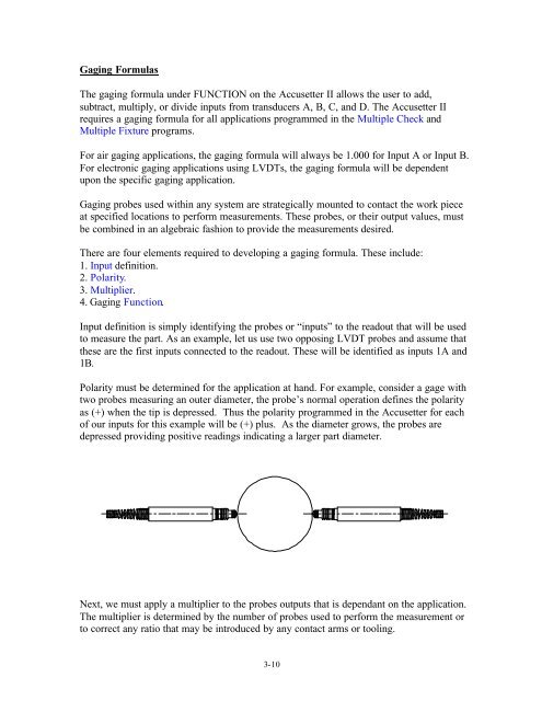
Polarity must be determined for the application at hand. For example, consider a gage with<br />
two probes measuring an outer diameter, the probe’s normal operation defines the polarity<br />
as (+) when the tip is depressed. Thus the polarity programmed in the <strong>Accusetter</strong> for each<br />
of our inputs for this example will be (+) plus. As the diameter grows, the probes are<br />
depressed providing positive readings indicating a larger part diameter.<br />
Next, we must apply a multiplier to the probes outputs that is dependant on the application.<br />
The multiplier is determined by the number of probes used to perform the measurement or<br />
to correct any ratio that may be introduced by any contact arms or tooling.<br />
3-10