

FREE DVD
FREE DVD
FREE DVD

Create successful ePaper yourself
Turn your PDF publications into a flip-book with our unique Google optimized e-Paper software.
HANDS-ON<br />
ELECTROCARDIOGRAPH<br />
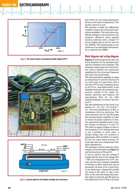
255<br />
N ECG<br />
0<br />
1V75<br />
V ECG<br />
4V25<br />
050280 - 14<br />
ple). These are very high-performance<br />
devices and need no adjustment. But<br />
quality comes at a cost.<br />
We decided to make the differential<br />
amplifier using more economical operational<br />
amplifiers. This also allows significant<br />
savings in cost and power consumption.<br />
Moreover, these opamps<br />
function perfectly with a single 5 V<br />
power supply (this is not the case for<br />
the AD624). The disadvantage is the<br />
presence of an adjustable potentiometer<br />
to optimise the CMRR.<br />
Figure 5. The transfer function is determined by divider bridge R3/R12.<br />
RAM_CS<br />
RD<br />
WR<br />
ECLK<br />
+5V<br />
1<br />
top view<br />
A0 - A15<br />
GAME BOY<br />
D0 - D7<br />
32<br />
RESET<br />
AUDIO IN<br />
GND<br />
050280 - 15<br />
Figure 6. Connector pinout for the Gameboy cartridge (view from above).<br />
Block diagram and wiring diagram<br />
Figures 3 and 4 respectively give the<br />
block diagrams for the analogue part<br />
and the complete circuit diagram. The<br />
references associated with each function<br />
(ICx.y) identify the operational<br />
amplifiers for the structural diagrams<br />
that show the functionality.<br />
The instrumentation amplifier is made<br />
up of functions F1 and F2. Function F3<br />
is a 2nd order low pass filter with a<br />
roll-off of 170 Hz and a damping factor<br />
m of 0.73 (i.e., near Butterworth). It will<br />
faithfully attenuate all unwanted components<br />
outside of the useful frequency<br />
spectrum and replaces the<br />
anti-aliasing filter for the DAC<br />
(digital/analogue converter) that follows<br />
it.<br />
The gain distribution in the circuit is as<br />
follows: A1 = 21×, A2 = 4.7× and A3 =<br />
10×. The total amplification is 987, in<br />
compliance with our objectives. The<br />
other functions (F4, F5 and F6) assist<br />
the instrumentation amplifier in order<br />
to ensure its proper operation. In fact,<br />
the operational amplifiers have a supply<br />
voltage of between 0 V and 5 V.<br />
The ideal no-signal voltage on each of<br />
the terminals is 2.5 V. Setting this level<br />
is not a problem in most cases: a<br />
divider bridge with two resistors is<br />
appropriate (R23 and R24). It is harder<br />
for the two input amps because we<br />
must take care not to compromise their<br />
input impedances.<br />
The problem is solved using the third,<br />
common, ECG electrode (see Figure 3)<br />
and the functions of F4 and F5.<br />
It can be shown that the voltage S<br />
equals half the sum of the voltage (EA<br />
+ EB). It is compared to the ‘2.5-V’ setting,<br />
and the error voltage is amplified<br />
to produce an ECG signal that can be<br />
processed. As there is no current flow<br />
in the electrodes, voltages EA and EB<br />
are equal to EC (give or take a few<br />
mV). In this way, the human skin actually<br />
helps to keep EA and EB equal to<br />
the target level of 2.5 V. That is the goal<br />
36<br />
elektor electronics - 10/2006


