

FREE DVD
FREE DVD
FREE DVD

You also want an ePaper? Increase the reach of your titles
YUMPU automatically turns print PDFs into web optimized ePapers that Google loves.
HANDS-ON<br />
DESIGN TIPS<br />
Metal film resistor trimming<br />
K. Bertholdt<br />
Suppose you need an oddball<br />
resistor value like 2.8 kΩ but you<br />
only have 2.2 kΩ available. Of<br />
course you can create the desired<br />
value from two or more standard<br />
resistors (if available!) or employ<br />
a preset as a makeshift solution<br />
(space allowing). There is, however,<br />
an alternative, cheekier<br />
method that seems to be little<br />
known, hence this Design Tip.<br />
Connect your 2.2 kΩ resistor to<br />
an ohmmeter (or a multimeter set<br />
to the Ω range). Next, use a<br />
sharp hobby knife to scratch a<br />
tiny amount of lacquer off the<br />
resistor body. You’ll find that careful<br />
scratching increases the value<br />
of the resistor as effectively the<br />
metal film layer is reduced. You’ll<br />
be surprised how easily a metal<br />
film resistor can be trimmed to a<br />
slightly higher value!<br />
(050295-1)<br />
Editor’s note<br />
As already intimated by the<br />
author, the method is fairly brutal,<br />
hence should only be used in<br />
experimental situations or when<br />
no alternative is available. The<br />
damaged resistor loses its rated<br />
wattage and mechanical stability,<br />
while the bared metal film is not<br />
a permanent solution.<br />
In circuits designed for regular<br />
use resistors with the proper value<br />
should be used, or failing that, a<br />
combination of standard undamaged<br />
resistors approaching the<br />
desired value.<br />
Logarithmic volume control<br />
Bart Boerman<br />
This volume control makes use of<br />
an operational amplifier and a<br />
few passive components to mimic<br />
the operation of a logarithmic<br />
control while using a linear potentiometer.<br />
The circuit does better in<br />
terms of reliability when compared<br />
to other designs employing<br />
double linear pots to create the<br />
logarithmic transfer function.<br />
The circuit is also handy when<br />
digital potentiometers are used,<br />
the majority of these being linearlaw.<br />
The circuit shown here<br />
allows such a digital pot to be<br />
easily changed into its logarithmic<br />
counterpart.<br />
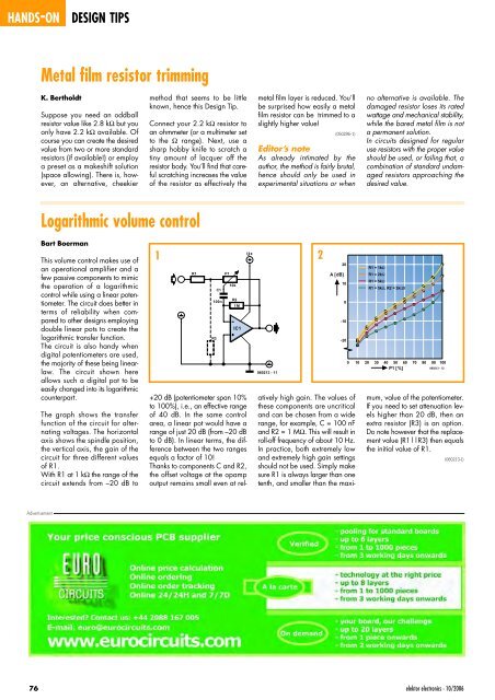
The graph shows the transfer<br />
function of the circuit for alternating<br />
voltages. The horizontal<br />
axis shows the spindle position,<br />
the vertical axis, the gain of the<br />
circuit for three different values<br />
of R1.<br />
With R1 at 1 kΩ the range of the<br />
circuit extends from –20 dB to<br />
U+<br />
1 2<br />
R1<br />
R2<br />
1M<br />
IC1<br />
+20 dB (potentiometer span 10%<br />
to 100%), i.e., an effective range<br />
of 40 dB. In the same control<br />
area, a linear pot would have a<br />
range of just 20 dB (from –20 dB<br />
to 0 dB). In linear terms, the difference<br />
between the two ranges<br />
equals a factor of 10!<br />
Thanks to components C and R2,<br />
the offset voltage at the opamp<br />
output remains small even at rel-<br />
R3<br />
C1<br />
100n<br />
P1<br />
10k<br />
060213 - 11<br />
A [dB]<br />
20<br />
10<br />
0<br />
-10<br />
-20<br />
R1 = 1kΩ<br />
R1 = 2kΩ<br />
R1 = 5kΩ<br />
R1 = 5kΩ, R2 = 2kΩ5<br />
0 10 20 30 40 50 60 70 80 90 100<br />
P1 [%]<br />
060213 - 12<br />
atively high gain. The values of<br />
these components are uncritical<br />
and can be chosen from a wide<br />
range, for example, C = 100 nF<br />
and R2 = 1 MΩ. This will result in<br />
roll-off frequency of about 10 Hz.<br />
In practice, both extremely low<br />
and extremely high gain settings<br />
should not be used. Simply make<br />
sure R1 is always larger than one<br />
tenth, and smaller than the maximum,<br />
value of the potentiometer.<br />
If you need to set attenuation levels<br />
higher than 20 dB, then an<br />
extra resistor (R3) is an option.<br />
Do note however that the replacement<br />
value (R1||R3) then equals<br />
the initial value of R1.<br />
(060213-I)<br />
Advertisement<br />
76<br />
elektor electronics - 10/2006


