

FREE DVD
FREE DVD
FREE DVD

You also want an ePaper? Increase the reach of your titles
YUMPU automatically turns print PDFs into web optimized ePapers that Google loves.
pull-down resistors R12 and R16 are<br />
copied from the original ICD module.<br />
The series resistors R11, R15 and R17<br />
limit the output current of the host<br />
hardware under short circuit conditions<br />
to a value that is not going to<br />
cause trouble for IC1. D4 protects the<br />
circuit against excessive supply voltage<br />
or reverse polarity. In view of the<br />
intentionally restricted functionality of<br />
this unit some care is necessary, as<br />
D4 may not be able to compete with<br />
an laboratory power adjusted to 30 V<br />
and 5 A.<br />
Analogue inputs RA0, RA1 and RA3<br />
measure the level of the programming<br />
voltage and the supply voltage at the<br />
Reset pin of the host hardware. The<br />
test values are monitored in the development<br />
environment and are displayed<br />
in the “Debugger/Settings/Power”<br />
window. For absolute precision the<br />
voltage divider can be built using 1%<br />
(close tolerance) resistors.<br />
The LEDs D5 to D7 indicate the presence<br />
of the operating voltage, an operation<br />
in process in IC1 or a fault condition.<br />
As in the Microchip ICD2, the<br />
Power LED (D7) is green, the Busy LED<br />
(D6) yellow and the Error LED (D5) red.<br />
Printed circuitboard and<br />
Bootloader<br />
Since the single-sided PCB (Figure 2)<br />
is populated using conventional-size<br />
components with normal wire leads<br />
and is not cramped, construction is<br />
possible inside an hour, even for those<br />
less skilled at soldering. After fitting<br />
the components and making connection<br />
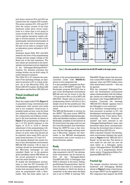
to the host hardware as shown in<br />
Figure 3 the programming voltage on<br />
pin 2 of IC2 should measure in the<br />
region of 12.75 to 13.25 V. Precise<br />
adjustment of the programming voltage<br />
can be made by altering R1 if necessary.<br />
In most cases this should not<br />
be required, since many PICs can tolerate<br />
levels between 12 V and 14 V.<br />
If not already obtained, the current version<br />
of the development environment<br />
MPLAB IDE (version 7.40 at time of<br />
writing) should be downloaded from<br />
the Microchip homepage [1] and<br />
installed. Reply ‘no’ to the question<br />
about installing custom USB drivers, as<br />
the circuit presented in this article<br />
uses the serial interface.<br />
To enable the development environment<br />
to load the PIC Controller IC1<br />
with firmware appropriate to the particular<br />
host processor being used, IC1<br />
must be programmed with a Bootloader.<br />
This has been taken care of<br />
PC<br />
RS232<br />
test and programming module<br />
PIC16F877<br />
+13V<br />
220 Ω<br />
already in the pre-programmed microcontroller<br />
(order code 050348-41)<br />
shown in the component list.<br />
It is also possible to program the Bootloader<br />
into a PIC16F877 oneself. The<br />
Bootloader program BL010101.hex is<br />
part of the development environment<br />
MPLAB and can be found in the file<br />
‘\Programme\Microchip\MPLAB<br />
IDE\ICD2’. People with no access to a<br />
programming device will find in [3] a<br />
simple circuit for the parallel port; this<br />
can be made up on vero board or handwired.<br />
The MPLAB Bootloader is written for<br />
the 16F877. The more recent 16F877A<br />
employs a modified programming algorithm<br />
and therefore requires a modified<br />
Bootloader, available on the Internet at<br />
[5] (scroll down the page until you see<br />
the word Bootloader) and elsewhere.<br />
Using the 16F877A runs a risk, however,<br />
that the Debugger will stop working<br />
if Microchip replaces the Bootloader<br />
in the MPLAB development<br />
environment with a new version in a<br />
future firmware update.<br />
Ready<br />
With the circuit and programmed IC1<br />
chip connected to the PC, the development<br />
environment can be started up.<br />
First off the ‘Debugger/Select<br />
Tool/MPLAB ICD2’ of Debugger type<br />
ICD2 is selected. In the menu ‘Debugger/Settings/Communication’<br />
that follows<br />
the next task is to nominate the<br />
serial interface to which the device is<br />
connected. In the same menu the Baud<br />
rate is set to 57600. A warning ‘ICD-<br />
220<br />
Ω<br />
220 Ω<br />
4k7<br />
4k7<br />
TGT VCC<br />
TGT MCLR<br />
TGT PGD<br />
TGT PGC<br />
GND<br />
100k<br />
Rc<br />
100k<br />
Rb<br />
target system (TGT)<br />
10k<br />
Ra<br />
1<br />
40<br />
39<br />
MCLR<br />
PGD<br />
PGC<br />
VSS<br />
Warn0034: Please ensure that your system’s<br />
serial FIFO buffers are disabled’<br />
appears when the FIFO buffers have<br />
been deactivated correctly — this can<br />
be ignored.<br />
With the command ‘Debugger/Connect’<br />
the development environment<br />
opens communication with the Debugger,<br />
carries out a self-test and displays<br />
the result in the ‘Output/MPLAB ICD 2’<br />
window. Curiously the message<br />
‘MPLAB ICD 2 Ready’ appears even if<br />
the Debugger is not connected.<br />
If no firmware corresponding to the<br />
host processor is present in IC1, the<br />
development environment will suggest<br />
downloading this. If the option ‘Automatically<br />
download firmware if<br />
needed’ has been selected in the<br />
‘Debugger/Settings/Status’ menu, this<br />
download takes place automatically.<br />
During the download time of about a<br />
minute the Busy-LED D6 is lit.<br />
After a renewed ‘Connect’ the development<br />
environment displays the result<br />
seen in Figure 4 with ‘MPLAB ICD 2<br />
Ready’ on the last line. The device is<br />
now ready for use and can now be<br />
used either as a Debugger (menu<br />
choice ‘Debugger/Select Tool/MPLAB<br />
ICD2’ or as a programming device<br />
(menu option ‘Programmer/Select Programmer/MPLAB<br />
ICD 2’).<br />
Practical tips<br />
The sample interface between host<br />
hardware and Debugging Module<br />
shown in Figure 3 using a host processor<br />
of type 16F877 can be applied to all<br />
PIC computers that support the ICD2<br />
11<br />
VCC<br />
32<br />
VCC<br />
PIC16F877<br />
12 13 14<br />
U b = +5V<br />
VSS<br />
31<br />
050348 - 12<br />
Figure 3. Five wires provide the connection from the ICD/ICP module to the target system.<br />
10/2006 - elektor electronics 53


