Here - LF-Technik
Here - LF-Technik
Here - LF-Technik

You also want an ePaper? Increase the reach of your titles
YUMPU automatically turns print PDFs into web optimized ePapers that Google loves.
1 ______________________________________<br />
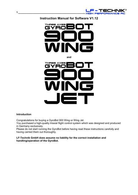
Instruction Manual for Software V1.12<br />
and<br />
<br />
Introduction<br />
Congratulations for buying a GyroBot 900 Wing or Wing Jet.<br />
You purchased a high-quality triaxial flight control system which was designed and produced<br />
in Germany exclusively.<br />
Please do not start running the GyroBot before having read these instructions carefully and<br />
having carried them out thoroughly.<br />
<strong>LF</strong>-<strong>Technik</strong> GmbH does assume no liability for the correct installation and<br />
handling/operation of the GyroBot.
2 ______________________________________<br />
Index of contents<br />
Page<br />
Chapter<br />
1 Introduction,Index of Contents<br />
2 Scope of Delivery, What is GyroBot 900 Wing?<br />
4 Which Models are suited?<br />
6 Fixture in the Model<br />
11 Plug Connection on GyroBot and Extensionboard<br />
12 Menu Struktur<br />
13 Declaration of the Flight Phase Switch and of the<br />
Programming<br />
14 Programming of the GyroBot 900 Wing and Jet<br />
21 Declaration of P- and I Part<br />
22 Declaration of "RC-Gain"<br />
23 Declaration of "Airspeed"<br />
24 Declaration of Trimming with the GyroBot 900 Wing and Jet<br />
26 The first Flight<br />
28 Installation of Software-Updates<br />
29 Technical Data<br />
Scope of Delivery<br />
Depending on which components you ordered, the following parts are included in the<br />
box:<br />
Ord.No. 5002:<br />
1. GyroBot 900 Wing with Extension Board and Pitot Tube<br />
2. 7 three pole cables (double sides servo connector male) with a length of 10cm<br />
(optional other lenghtes are available)<br />
3. 4m of Festo 3mm Tube<br />
4. 2 Festo Connectors 3mm<br />
5. 3 Self-Adhesive Pads<br />
6. CD with Software und Manual<br />
7. Decals<br />
Ord.No. 5000/1:<br />
1. USB Interface Cable (to program via PC or Laptop and for updating)<br />
Ord.No. 5000/2:<br />
1. „Cockpit“ Programming Box (to program without your PC)<br />
2. 1 three pole cable (servo connector male-servo connector female)
3 ______________________________________<br />
Ord. No. 5002 Ord. No. 5000/1 Ord. No. 5000/2<br />
What is GyroBot 900 Wing?<br />
It is a world novelty. The GyroBot 900 Wing is a high-quality and precise flight control system<br />
with stabilisation of the aileron, elevator and rudder axis of a model airplane. Aileron, elevator<br />
and rudder ar controlled by the GyroBot. Thereby the flight characteristics of each plane will<br />
be improved of that effect that the model flies „like on rails“. A fully adjusted GyroBot 900<br />
Wing will always keep the model in the position you brought it to with the control sticks. But it<br />
never works against your inputs from the transmitter. The throttle function is not considered.<br />
This means for you: The model flies much better and more precise as without GyroBot, flying<br />
will be much easier. For example flying aerobatics is much easier because the GyroBot<br />
controls all „static“ figures itself after you brought the model into the right position.<br />
You must not switch on and off the GyroBot for doing aerobatic figures. You can fly the whole<br />
flight (except of the start and landing) with active GyroBot on all 3 axes (if you use an<br />
aerobatic machine). Figures like inverted, knife edge, hovering and torqueroll are completely<br />
controlled by the GyroBot. You only have to bring the model into the right position and then<br />
loose the stick (except of the throttle).<br />
During normal flight you only have to move the sticks if you want to change the direction or<br />
position of the plane, but you don´t have to do anything against restlessness of the plane or<br />
against wind impacts. GyroBot always keeps the model in the relative position, it does not<br />
orient itself on the horizon or on the cardinal points.<br />
GyroBot 900 Wing is not authorized for turbine powered Jetmodels!!!<br />
What is GyroBot 900 Wing Jet?<br />
GyroBot 900 Wing Jet is a version of GyroBot 900 Wing which is authorized for operating in<br />
Gas Turbine Jets.<br />
It is also authorized for all other kinds of model airplanes and it can be handled and<br />
programmed similar to the GyroBot 900 Wing. The only „disadvantage“ ist the higher weight<br />
and the bigger case.<br />
For flying Gas Turbine Jets you MUST use GyroBot 900 Wing Jet!!!<br />
Can I switch on and off the GyroBot during flight?<br />
Yes, via the flight phases. GyroBot 900 Wing has 3 flight phases which can be configured<br />
completely free. The control of each axis can be switched on or off during flight via switching<br />
between the different flight phases. For example if the control is off for all 3 axes in flight<br />
phase 1 and the control is on for all 3 axes in flight phase 2 you can switch between control<br />
off and on via switching between flight phase 1 and 2 during flight. For example you only can<br />
put on the control for the rudder (or elevator, or ailerons) in one flight phase.
4 ______________________________________<br />
CAUTION:<br />
WITH THE ORDER OF THIS UNIT YOU INSURE TO US THAT YOU ALWAYS<br />
CONFIGURE THE FLIGHT PHASE 1 WITH COMPLETE CONTROL OFF FOR ALL 3<br />
AXES.<br />
(You can switch the complete control off in the particular „Tuning“ Menu for aileron, elevator<br />
and rudder). The big advantage of this measure is that if you configured something wrong in<br />
the other flight phases (wrong sensor direction of rotation or too high P and I values), you<br />
can switch back to flight phase 1 and the models flies like before without GyroBot.<br />
Please do also use the flight phase 1(control for all axes OFF) always for starting and landing<br />
as long as you are not very familiar with the system.<br />
Another reason for the basic necessity of a flight phase without any control is if there are<br />
sensor failures or errors for any reason, your model perhaps would become uncontrollable if<br />
the control of the GyroBot is on. In these cases you can switch back to flight phase 1 (control<br />
for all axes OFF) and your model can be controlled by you as if you don´t use a GyroBot.<br />
GyroBot 900 Wing does NOT know, if a flight attitude is right or wrong. If you bring the model<br />
into a vertical nose dive and loose the sticks the Gyrobot will also keep the model in this<br />
direction until it crashes. Furtermore it cannot work against the physics. So if there is a stall<br />
also the GyroBot cannot help.<br />
When should the control always stay OFF ?<br />
1. During approach and landing the elevator control should always be OFF, because with<br />
active elevator control a stall would not signalize itself before (the model does not take the<br />
nose a bit down like without control), but it would come very abruptly. The model would keep<br />
its attitude as long as the stall comes very abruptly.<br />
Thereforee please note the following: ELEVATOR CONTROL ALWAYS OFF DURING<br />
APPROACH, LANDING AND ALL SLOW AND LOW FLIGHTS WITH UNSUITABLE<br />
MODELS.<br />
2. During stationary stand or if the plane will be carried or driven to the starting point the<br />
control of all 3 axes should be off. (Please use flight phase 1 here).<br />
The reason is as follows: GyroBot only can work correct if the control circuit is closed i.e. if<br />
the plane can rotate around all degrees of freedom. This is not warrantied if the model does<br />
not yet fly. So the model could not follow the corrections of the Gyrobot and as soon as it<br />
would lift off it would make a short but very fast move (as long as the control circuit is<br />
closed). We want to avoid this „Moment of Shock“, so please don´t switch on the control<br />
before the model is in the air (as long as you are very familiar with the system).<br />
The right procedure for the start is as follows:<br />
If you carry or drive the model to the starting point, please always use flight phase 1<br />
(complete control OFF). During the start you can use a flight phase with only the rudder<br />
control ON, if you want. If the model is in the air, you can switch to a flight phase with control<br />
ON on all axes, if you want this.<br />
PLEASE DO NOT START WITH CONTROL ON FOR AILERON AND ELEVATOR !!!
5 ______________________________________<br />
Which models are suitable?<br />
In principle all aerodynamical controlled model airplanes (no deltas and no models with V<br />
Tail at the moment) are suitable, but not a control of all three axes is ok for all kinds of<br />
models and for all flying attitudes.<br />
<strong>Here</strong> you find whats right or wrong for the separate model types.<br />
1. Aerobatic models:<br />
On 3D or Aerobatic Models the performance of the GyroBot can be practiced very good. With<br />
a flight phase with control ON on all 3 axes many very difficult aerobatic maneuvers run<br />
automatically. You only have to bring the model into the right position, then you can loose the<br />
sticks completely (except of the throttle) and the GyroBot 900 Wing will keep the model in<br />
knife edge flight, inverted flight, normal straight flight, hovering, torqueroll etc.<br />
So all “static” figures (figures which do not need any control for the figure itself, but only for<br />
keeping the model in this position) can be flow by the GyroBot, if you bring the model into the<br />
right position once.<br />
For example for the knife edge flight you only have to bring the model in the right position if<br />
you do a quarter roll and then lift the nose a little bit with the rudder, then the sticks can be<br />
released completely.<br />
Also very complicated figures like for example a horizontal knife edge eight is very easy now,<br />
because you only have to control the “eight” with the elevator stick, that’s it. No corrections<br />
of the rudder or aileron should be necessary. This schema can be carried to all other figures.<br />
2. Jets:<br />
CAUTION:<br />
GyroBot 900 Wing is not authorized for turbine powered Jetmodels, only for EDF Jets.<br />
For flying turbine Jets you MUST use GyroBot 900 Wing Jet!!!<br />
In slow flight and in approach for landing jetmodels often will be unstable and not easy to<br />
control. Special on the aileron axis jets often are instable. This will be avoided effectively with<br />
control ON on this axis. Control ON on the rudder axis makes the jet run very straight on the<br />
runway during the start.<br />
For large scale jet aerobatics or normal jet flying with enough speed control ON on all 3 axes<br />
is ideal. The model flies like on rails. Negative characteristics of the plane or wind influences<br />
will be corrected perfectly.<br />
3. Airplane Towing (Both Towing Model and Glider):<br />
<strong>Here</strong> you can use the GyroBot 900 Wing in both the towing plane and the sailplane. As both<br />
models fly straight with loosen sticks the whole aero tow flight steadies itself.<br />
For example it is also possible to “command” an angle of climb with the elevator stick to the<br />
towing plane which will be permanently kept. At will the control of each axis can be put on or<br />
off during flight. So the advantage is: Same speed during the whole towing on both planes<br />
and thereby also the cord is always tensed to the same level.<br />
If the aero tow is higher its more and more difficult to control the right position with the<br />
ailerons. With control ON on the aileron axes this is also no problem.<br />
In the glider during towing there should be an active control on the aileron axes, but not on<br />
the elevator and rudder axis.<br />
4. Gliders:<br />
<strong>Here</strong> you have to distinguish:<br />
In aerobatic gliders during the programm a control ON on all axes is good as long as the<br />
speed is high enough.
6 ______________________________________<br />
CAUTION: If the speed is too low the stall comes very abruptly. If you want to avoid<br />
this, please switch OFF the control on the elevator axis.<br />
At thermalling in circle the control for elevator and aileron should be OFF, because otherwise<br />
the plane will not show you any more where the thermals are because it will no more “shake”<br />
the wings for example. Control ON on the rudder axis can be wise for continuous circles with<br />
the same diameter.<br />
If you use a Variometer also the aileron control can be ON.<br />
During straight flight between 2 thermal fields control ON on all axes could be useful, if there<br />
is enough speed.<br />
The same counts for F3B or F3F competitions.<br />
For all gliders counts: Elevator control OFF for the landing. (Stall!).<br />
5. For beginners:<br />
For the beginner it is a big easing to fly with GyroBot 900 Wing.<br />
A Trainer model with active control has no „live of its own“ anymore. Thereby the pilot must<br />
control only if he wants to change the direction. So flying a model airplane could become<br />
nearly as easy as driving a RC Car.<br />
Of course there are many more Types of RC planes which flying characteristics can be<br />
improved with the GyroBot.<br />
Installation in the model:<br />
Some important informations about vibrations:<br />
You always should fix the GyroBot 900 Wing with ONE ORIGINAL SE<strong>LF</strong>-ADHESIVE<br />
PAD in the model. The GyroBot 900 Wing Jet can be mounted with one and a half Pad<br />
(in longitudinal direction one after another).<br />
In particular if you use large Gas Engines from 20 cc up to more than 250 cc which<br />
cause heavy vibrations it is VERY IMPORTANT that the GyroBot is fixed on a VERY<br />
SOLID BOARD which is connected VERY FIRMLY with the fuselage. The board MUST<br />
NOT swing or bend itself.<br />
The 1-2 mm thick boards in the AFR planes are UNSUITABLE.<br />
The board should be made from min. 6-8mm thick high quality plywood.<br />
In electric or turbine models it is less critical.<br />
The main unit of the GyroBot 900 Wing MUST be fixed PARALLEL to all 3 main axes of<br />
the plane.<br />
That means, it must be parallel to the roll-axis, to the pitch-axis and to the vertical (yaw) –<br />
axis. It should be fixed near the receiver and the power management system.<br />
The plug board of the GyroBot must look towards the front or the rear of the plane, but<br />
NOT to the left or to the right.<br />
It must not be fixed in the CG of the plane.<br />
Please ONLY USE ONE of the ORIGINAL double sided mounting pads which are included.<br />
Please fix it on a clean, smooth and stable surface which is solidly bonded to the fuselage.<br />
For GyroBot 900 Wing Jet you can use 1,5 Pads next to each other in the length direction.<br />
Please consider a good adhesion of the pad and the GyroBot.
7 ______________________________________<br />
The following pictures show the right installation of the GyroBot in the model:<br />
Installation in an electric powered model<br />
Installation in a gas engine powered model
8 ______________________________________<br />
Installation in a turbine powered model<br />
Never fix the unit bevelled to one of the 3 main axes.<br />
The pitot tube must be fixed on the tip of one of the wings and parallel to the roll-axis.<br />
It must NOT be fixed on the fuselage.<br />
You can fix it with a part of one pad between the wing and the tube and with 2 or 3 stripes of<br />
adhesive film. You also can glue it into the nose of the wing, but please think of the 20 mm<br />
distance as shown in the following picture.
9 ______________________________________<br />
Now you must halve the 3mm Festo Tube and put the 2 tubes on the 2 brass pipes of the<br />
pitot tube. (If its too loose please use VERY LESS speed glue to safe them).<br />
Before you thread the tubes through the wing you must mark both ends of one tube with a<br />
permanent marker pen.<br />
Now please thread the tubes through the wing and pull them out on the root rib. In the<br />
fuselage the 2 tubes will be connected with the extension board as shown in the pictures.<br />
Please necessarily consider the right polarity.<br />
The tube which is on the straight brass pipe of the pitot tube must be connected to the upper<br />
pin on the extension board, the tube on the angulate brass pipe must be connected to the<br />
lower pin on the extension board.<br />
Connection Schema:<br />
The right place for the Extensionboard:<br />
Ideally the Extensionboard should be fixed with a part of one included pad in the fuselage<br />
near the GyroBot main unit. The position and direction of the board is equal.<br />
If you fix it in the fuselage, you must cut both 3mm Festo tubes and connect then again with<br />
the 2 Festo connectors. Then you only have to disconnect the Festo connectors if you want<br />
to remove the wing from the fuselage.
10 ______________________________________<br />
To close the connection push the ends of the tubes tight into the connector. To open the<br />
connection you must push back the blue plate on one end of the connector and then pull out<br />
the tube.<br />
CAUTION: Necessarily mark the 2 ends of one tube before and after the connector<br />
with a piece of heatshrink (not too hot because of the tube) or colored adhesive film to<br />
avoid a permutation, otherwise the control does not work right.<br />
If it is possible, you also can fix the Extension Board into the Wing near the root rib. Then you<br />
only have to remove the servo connectors if you want to remove the wing. Then you don´t<br />
need the Festo connectors.<br />
If you fixed all parts correctly in the model please connect the GyroBot and Extension Board<br />
with the receiver of power management system.<br />
If you use a power management system (Powerbox, DPSI …) the GyroBot must be<br />
connected between the receiver and the power management system.<br />
If not, the GyroBot must be connected between the receiver and the servos.<br />
Therefore please use the following table:
11 ______________________________________<br />
The connectors on the GyroBot 900 Wing (and Wing Jet) and Extension Board are<br />
glazed as follows:<br />
Slot at<br />
GyroBot<br />
Declaration<br />
1 For Programming and Updating via Cockpit or USB Interface Cable<br />
2 Rudder Output (to the Rudder Servo)<br />
3 Rudder Input (Rudder Channel from the Receiver)<br />
4 Aileron Input (Aileron Channel from the Receiver)<br />
5 Elevator Input (Elevator Channel from the Receiver)<br />
6 Connection to the Extension Board (Plug there on Slot 4)<br />
7 Input for Flight Phase Switch (Plug into a free Channel on the Receiver<br />
which can be operated with a 3 step switch on the transmitter)<br />
8 Elevator Output 1 (to the Elevator Servo 1)<br />
9 Elevator Output 2 (to the Elevator Servo 2) if its existing<br />
10 Aileron Output 1 (to the Aileron Servo 1)<br />
11 Aileron Output 2 (to the Aileron Servo 2) if its existing<br />
Slot at<br />
Extension<br />
Board<br />
Declaration<br />
1 For later Add Ons, not used at the moment<br />
2 For later Add Ons, not used at the moment<br />
3 For later Add Ons, not used at the moment<br />
4 Connection to the GyroBot (Plug there on Slot 6)<br />
5 Input RC-Gain (Gain Adjustment from the Transmitter) (Plug into a free<br />
Channel on the Receiver which can be operated with a control dial or a slider<br />
on the transmitter)<br />
6 For later Add Ons, not used at the moment<br />
If you have all plugs connected right you can start with programming the transmitter and the<br />
GyroBot.<br />
Preparation/Programming of the Transmitter<br />
1. Choose a new model memory<br />
2. Switch off all Mixers<br />
3. Set ATV for Elevator, Rudder, Aileron to +/-100%<br />
4. Set all trims to center position<br />
5. Fix the 3 step switch for the flight phase switch and a control dial or a slider for the<br />
RC-Gain on the transmitter<br />
For your explanation:<br />
All servo travels, reverses, centers (for aileron, elevator and rudder) will be adjusted in<br />
the GyroBot now and no more in the transmitter. The agility of the plane can be<br />
adjusted with the servo travel (ATV) of the particular axis (for example if you want that<br />
the model makes faster rolls you have to increase the servo travel for the aileron). This<br />
counts for all 3 axes.
12 ______________________________________<br />
Please consider the following menu structure first:<br />
Menu Structure GyroBot 900 Wing (and Wing Jet) Software Version V1.11<br />
System<br />
Running<br />
German /<br />
English<br />
Calibrate<br />
Modell Type<br />
Rudder<br />
Base<br />
Rudder<br />
Tuning<br />
Elevator<br />
Base<br />
Elevator<br />
Tuning<br />
Aileron<br />
Base<br />
Aileron<br />
Tuning<br />
Check It<br />
Copy Phase<br />
Release<br />
sticks and<br />
press<br />
button<br />
Standard<br />
Rudder<br />
Servo<br />
centered<br />
Rudder<br />
Control<br />
On/Off<br />
Elevator<br />
Servos<br />
centered<br />
Elevator<br />
Control<br />
On/Off<br />
Aileron<br />
Servos<br />
centered<br />
Aileron<br />
Control<br />
On/Off<br />
Inputs<br />
from [ ]<br />
to [ ]<br />
Vibration<br />
Filter<br />
Rudder<br />
Center<br />
Rudder P /<br />
RC Gain<br />
On/Off<br />
Elevator<br />
Servo 1<br />
Direction<br />
Elevator P /<br />
RC Gain<br />
On/Off<br />
Aileron<br />
Servo 1<br />
Direction<br />
Aileron P /<br />
RC Gain<br />
On/Off<br />
Extension<br />
Board<br />
Servo<br />
Frequency<br />
Rudder<br />
Minimum<br />
Rudder I /<br />
RC Gain<br />
On/Off<br />
Elevator<br />
Servo 2<br />
Direction<br />
Elevator I /<br />
RC Gain<br />
On/Off<br />
Aileron<br />
Servo 2<br />
Direction<br />
Aileron I /<br />
RC Gain<br />
On/Off<br />
Gyrosensor<br />
Rudder<br />
Maximum<br />
Rudder<br />
Deadband<br />
Elevator<br />
Servo 1<br />
Center<br />
Elevator<br />
Deadband<br />
Aileron<br />
Servo 1<br />
Center<br />
Aileron<br />
Deadband<br />
Accelerometer<br />
Rudder<br />
Gyro Direction<br />
Rudder<br />
Airspeed<br />
On/Off<br />
Elevator<br />
Servo 2<br />
Center<br />
Elevator<br />
Airspeed<br />
On/Off<br />
Aileron<br />
Servo 2<br />
Center<br />
Aileron<br />
Airspeed<br />
On/Off<br />
Elevator<br />
Minimum<br />
Aileron<br />
Minimum<br />
Elevator<br />
Maximum<br />
Aileron<br />
Maximum<br />
Elevator<br />
Gyro Direction<br />
Aileron<br />
Gyro Direction
13 ______________________________________<br />
Declaration of the Flight Phase Switch<br />
Gyrobot 900 Wing offers 3 Flight Phases (3 Memories), which can be configured completely<br />
free. To switch between these 3 Flight Phases please connect the plug 7 on the GyroBot with<br />
a free plug on the Transmitter. Then you need a 3 step switch on the transmitter which<br />
switches this channel. You can see the current flight phase in the upper right corner of the<br />
GyroBot Display. A switching is only possible in the flying menu “System Running”.<br />
You always program the flight phase which you have choosen if you get into the<br />
programming menus (pushing the button a little bit longer, starting in „System Running“).<br />
Also during programming the current flight phase will be show in the display.<br />
You switch completely ALL values (all base and all tuning menus). Later you can copy the<br />
values from one to another flight phase in the “Copy Phase” menu. You always copy from the<br />
current phase to the phase you choose with the rudder stick.<br />
CAUTION: Please be sure that you have programmed (or copied from a programmed one)<br />
all flight phases. If you switch into a flight phase which is not programmed your plane will<br />
crash immediately.<br />
The agility of the separate axes will be adjusted with the servo travel (ATV, Endpoint) of the<br />
equal channel on the transmitter.<br />
For example if your plane shall fly faster rolls you have to increase the servo travel for the<br />
aileron function in the transmitter.<br />
Declaration of the Programming<br />
You can program the GyroBot 900 Wing either with the Cockpit Programming Box or with the<br />
USB Interface Cable and your PC or Laptop.<br />
If you use the Cockpit (which is the easiest and most comfortable way), you have to connect<br />
the Cockpit with the plug 1 of the GyroBot via the 70 cm Cable. Thereforee please put a<br />
10cm Patchcable (two servo connectors) into plug 1 and then connect this with the 70 cm<br />
cable. The other side of the 70 cm cable must be plugged into one of the both connectors of<br />
the cockpit, equal which one it is (minus/GND is on the side of the button). The 10 cm Cable<br />
can always be left in the model for later programming.<br />
If you use a PC or Laptop, please connect the USB Interface Cable to a free USB Slot on the<br />
computer and to the 10 cm Cable on slot 1 of the GyroBot.<br />
Now you must start and install the file “cockpit.exe” from your GyroBot CD. System<br />
Requirements are Windows XP, Windows Vista or Windows 7.<br />
Then look for the right COM port in the program and then push the ON/OFF button until the<br />
GyroBot Start Menu “System Running” will be shown.<br />
Therefore the GyroBot must be connected and under voltage from your receiver battery.<br />
If the software does not work please install the following driver.<br />
http://www.ftdichip.com/Drivers/CDM/CDM20802_Setup.exe<br />
The driver is needed for using the USB Interface Cable, in newer Windows Versions it should<br />
not be necessary.
14 ______________________________________<br />
The programming is the same with the Cockpit or with the PC and will be handled as follows:<br />
Navigation through the<br />
menu >>><br />
Adjustment of Values >>><br />
Cockpit<br />
Programming Box<br />
Button<br />
Rudder Stick on<br />
the Transmitter<br />
PC and USB<br />
Interface Cable<br />
Space Bar on the PC or „Menu“<br />
button in the PC Cockpit Programm<br />
Rudder Stick on<br />
the Transmitter<br />
Every value is saved automatically if you leave the menu.<br />
For rudder, elevator and aileron there is one base menu and one tuning menu.<br />
In the base menus you can adjust basic settings like servo travel (ATV) etc., in the tuning<br />
menus the values like P and I gain will be set.<br />
The menu „Calibrate“ is used for reading the center positions of the transmitter and save<br />
them in the Gyrobot. In the “Check it” Menu nothing can be set, it shows you if the sensors,<br />
inputs etc. work right. In “Model type” at the moment you only can adjust “Standard”, later<br />
there will be more models types available. In “Copy Phase” you can copy the setting from<br />
one flight phase into the others.<br />
Programming of the GyroBot 900 Wing<br />
Now please take your completely assembled and installed plane and connect the GyroBot to<br />
the Cockpit or USB Cable. Then switch on first your transmitter first and then the receiver<br />
with the GyroBot.<br />
Caution: As long as the GyroBot „boots“ you MUST NOT move the model or the<br />
GyroBot. The system is booted if the green LED shines and if „System Running“ is<br />
displayed.<br />
On the GyroBot 900 Wing Jet you cannot see and LED, here you MUST NOT move the<br />
model as long as the servos make a short movement into the center position.<br />
PLEASE ALWAYS CONSIDER THIS, OTHERWISE THE UNIT WILL NOT WORK RIGHT<br />
DURING FLIGHT.<br />
Now switch into flight phase 1 with your 3 step switch on the transmitter (1 must be displayed<br />
in the right upper edge of the display).<br />
Choose your language<br />
Now press the button and keep it pressed. Now choose your language with the rudder stick<br />
and then loose the button.<br />
1 Calibrate<br />
Now you are in the menu Calibrate. Please press the button again, now you see “release the<br />
sticks and press the button”. Now loose all sticks and center all trims on the transmitter. Now<br />
press the button again. Now the GyroBot has read the center positions and saved them (but<br />
only for the current flight phase).<br />
Now you are again in the Start- and Flight Menu “System Running”.<br />
Important Information to Calibrating:<br />
Always if you change settings on the transmitter or the GyroBot the last step before
15 ______________________________________<br />
flying again should be „Calibrate“.<br />
Please always calibrate all 3 flight phases !<br />
2 Model Type<br />
Push the button a bit longer again and loose it then, now navigate to the menu<br />
Model Type with the rudder stick.<br />
At the moment you only can choose the mode type “Standard”. This is a normal plane with<br />
cross-tail or t-tail. Further model types will be available later via software update if customers<br />
wish them.<br />
Push the button again short, now you are in the menu Vibration Filter.<br />
Leave this value set to 1 at the moment. The Filter is important for models with gas engines<br />
which cause heavy vibrations. It will be set later. In electric or turbine models this value<br />
mostly can be left at 1.<br />
Push the button again short, now you are in the menu Servo Frequency.<br />
Now choose the right frequency with the rudder stick. If you don´t know it, please always<br />
choose „Standard“. Modern Digital- or Brushless Servos should be driven with „Speed“ or<br />
„High Speed“, but we cannot guarantee this.<br />
The rule of thumb is: If the servo runs smooth and does not make any abnormal sounds, the<br />
choosen frequency should be possible.<br />
We cannot guarantee that the servo does not get damaged. If you are not sure please<br />
choose „Standard“.<br />
Push the button again short, now you have done all settings in the menu Model Type and<br />
you are in the menu System Running again.<br />
3 Rudder Base<br />
Push the button a bit longer again and loose it then, now navigate to the menu<br />
Rudder Base with the rudder stick.<br />
Push the button again short, now you are in the menu Rudder Servo Centered.<br />
The rudder servos will be driven to the center position and you can adjust the rod or servo<br />
horn, if you want.<br />
Push the button again short, now you are in the menu Rudder Servo Center.<br />
Now please move the rudder exactly to the center position with the rudder stick.<br />
If the servo direction is wrong, please reverse the rudder channel in the transmitter and then<br />
set the rudder exactly to the center.<br />
Push the button again short, now you are in the menu Rudder Minimum.<br />
(This can be the left or right maximum position). The rudder automatically moves to the<br />
direction which maximum will be adjusted now. Now adjust the maximum position with the<br />
rudder stick.<br />
Push the button again short, now you are in the menu Rudder Maximum.<br />
(This is the other maximum position). The rudder automatically moves to the direction which<br />
maximum will be adjusted now. Now adjust the maximum position with the rudder stick.<br />
Push the button again short, now you are in the menu Rudder Gyro-Direction.<br />
<strong>Here</strong> you can reverse the effective direction of the rudder gyro, if this is possible.
16 ______________________________________<br />
Please do it as follows: Rotate the model around the rudder axis (vertical axis), the rudder<br />
must work against the rotation. If this is right, everything is ok. If this is wrong, please reverse<br />
the effective direction of the rudder gyro with the rudder stick.<br />
CAUTION: The effective direction and also the servo reverse must be absolutely<br />
correct for all 3 axes, otherwise your model will surely crash.<br />
Push the button again short, now you have done all settings in the menu Rudder Base and<br />
you are in the menu System Running again.<br />
(If the rudder is not exactly in the center now, please calibrate and repeat the setting Rudder<br />
Servo Center once more).<br />
4 Rudder Tuning<br />
Push the button a bit longer again and loose it then, now navigate to the menu<br />
Rudder Tuning with the rudder stick.<br />
Push the button again short, now you are in the menu Rudder Control.<br />
Because we program flight phase 1 at the moment (Control OFF on all 3 axes), please<br />
switch it OFF now with the rudder stick.<br />
(For your Information: Control "Off" means the complete control is off and the model flies like<br />
without GyroBot). If control is Off the following menu items will not be displayed.<br />
Push the button again short, now you have done all settings in the menu Rudder Tuning<br />
and you are in the menu System Running again.<br />
5 Elevator Base<br />
Push the button a bit longer again and loose it then, now navigate to the menu<br />
Elevator Base with the rudder stick.<br />
Push the button again short, now you are in the menu Elevator Servos Centered.<br />
The elevator servos will be driven to the center position and you can adjust the rods or servo<br />
horns, if you want.<br />
Push the button again short, now you are in the menu Elevator Servo 1 Direction.<br />
<strong>Here</strong> you can reverse the direction of the elevator servo 1. Please move the elevator stick to<br />
the up position (the position of the stick if the plane lifts the nose up), the elevator 1 also<br />
must go up no. If not, please reverse it with the rudder stick.<br />
Push the button again short, now you are in the menu Elevator Servo 2 Direction.<br />
<strong>Here</strong> you can reverse the direction of the elevator servo 2 (if it exists). Please move the<br />
elevator stick to the up position (the position of the stick if the plane lifts the nose up), the<br />
elevator 2 also must go up no. If not, please reverse it with the rudder stick.<br />
Push the button again short, now you are in the menu Elevator Servo 1 Center.<br />
Now please move the elevator 1 exactly to the center position with the rudder stick.<br />
Push the button again short, now you are in the menu Elevator Servo 2 Center.<br />
Now please move the elevator 2 exactly to the center position with the rudder stick (if it<br />
exists).<br />
Push the button again short, now you are in the menu Elevator Minimum.<br />
(This can be the upper or lower maximum position). The elevator automatically moves to the
17 ______________________________________<br />
direction which maximum will be adjusted now. Now adjust the maximum position with the<br />
rudder stick (for both elevator 1 and 2).<br />
Push the button again short, now you are in the menu Elevator Maximum.<br />
(This is the other maximum position). The elevator automatically moves to the direction<br />
which maximum will be adjusted now. Now adjust the maximum position with the rudder stick<br />
(for both elevator 1 and 2).<br />
For example: If “Maximum is “up”, then “Minimum” is “down”, but its also possible that<br />
“Maximum” is “down” and “Minimum” is “up”.<br />
Push the button again short, now you are in the menu Elevator Gyro-Direction.<br />
<strong>Here</strong> you can reverse the effective direction of the elevator gyro, if this is possible.<br />
Please do it as follows: Rotate the model around the elevator axis (lateral axis), the elevator<br />
must work against the rotation. If this is right, everything is ok. If this is wrong, please<br />
reverse the effective direction of the elevator gyro with the rudder stick.<br />
CAUTION: The effective direction and also the servo reverse must be absolutely<br />
correct for all 3 axes, otherwise your model will surely crash.<br />
Push the button again short, now you have done all settings in the menu Elevator Base and<br />
you are in the menu System Running again.<br />
6 Elevator Tuning<br />
Push the button a bit longer again and loose it then, now navigate to the menu<br />
Elevator Tuning with the rudder stick.<br />
Push the button again short, now you are in the menu Elevator Control.<br />
Because we program flight phase 1 at the moment (Control OFF on all 3 axes), please<br />
switch it OFF now with the rudder stick.<br />
(For your Information: Control "Off" means the complete control is off and the model flies like<br />
without GyroBot). If control is Off the following menu items will not be dispayed.<br />
Push the button again short, now you have done all settings in the menu Elevator Tuning<br />
and you are in the menu System Running again.<br />
7 Aileron Base<br />
Push the button a bit longer again and loose it then, now navigate to the menu<br />
Aileron Base with the rudder stick.<br />
Push the button again short, now you are in the menu Aileron Servos Centered.<br />
The aileron servos will be driven to the center position and you can adjust the rods or servo<br />
horns, if you want.<br />
Push the button again short, now you are in the menu Aileron Servo 1 Direction.<br />
<strong>Here</strong> you can reverse the direction of the aileron servo 1. Please move the aileron stick to<br />
the left position, the rudder also must go to the left now. If not, please reverse it with the<br />
rudder stick.<br />
Push the button again short, now you are in the menu Aileron Servo 2 Direction.<br />
<strong>Here</strong> you can reverse the direction of the aileron servo 2 (if it exists). Please move the<br />
aileron stick to the left position, the rudder also must go to the left now. If not, please reverse<br />
it with the rudder stick.
18 ______________________________________<br />
Push the button again short, now you are in the menu Aileron Servo 1 Center.<br />
Now please move the aileron 1 exactly to the center position with the rudder stick.<br />
Push the button again short, now you are in the menu Aileron Servo 2 Center.<br />
Now please move the aileron 2 exactly to the center position with the rudder stick (if it<br />
exists).<br />
Push the button again short, now you are in the menu Aileron Minimum.<br />
(This can be the left or right maximum position). The ailerons automatically move to the<br />
direction which maximum will be adjusted now. Now adjust the maximum position with the<br />
rudder stick (for both aileron 1 and 2).<br />
Push the button again short, now you are in the menu Aileron Maximum.<br />
(This is the other maximum position). The ailerons automatically move to the direction which<br />
maximum will be adjusted now. Now adjust the maximum position with the rudder stick (for<br />
both aileron 1 and 2).<br />
For example: If “Maximum is “left”, then “Minimum” is “right”, but its also possible that<br />
“Maximum” is “right” and “Minimum” is “left”.<br />
Push the button again short, now you are in the menu Aileron Gyro-Direction.<br />
<strong>Here</strong> you can reverse the effective direction of the elevator gyro, if this is possible.<br />
Please do it as follows: Rotate the model around the elevator axis (lateral axis), the elevator<br />
must work against the rotation. If this is right, everything is ok. If this is wrong, please<br />
reverse the effective direction of the elevator gyro with the rudder stick.<br />
CAUTION: The effective direction and also the servo reverse must be absolutely<br />
correct for all 3 axes, otherwise your model will surely crash.<br />
Push the button again short, now you have done all settings in the menu Aileron Base and<br />
you are in the menu System Running again.<br />
8 Aileron Tuning<br />
Push the button a bit longer again and loose it then, now navigate to the menu<br />
Aileron Tuning with the rudder stick.<br />
Push the button again short, now you are in the menu Aileron Control.<br />
Because we program flight phase 1 at the moment (Control OFF on all 3 axes), please<br />
switch it OFF now with the rudder stick.<br />
(For your Information: Control "Off" means the complete control is off and the model flies like<br />
without GyroBot). If control is Off the following menu items will not be dispayed.<br />
Push the button again short, now you have done all settings in the menu Aileron Tuning<br />
and you are in the menu System Running again.<br />
Adjusting and reducing of the rudder travels<br />
Please read this very watchful<br />
Now we adapt the servo travels (ATV´s, endpoints) in the transmitter for rudder,<br />
elevator and aileron. Therefore we act as follows:<br />
The GyroBot is in Flightmode „System Running“ in Flight Phase 1, we start with the<br />
rudder:
19 ______________________________________<br />
If you move the rudder stick now it is possible that the rudder is in maximum position<br />
as soon as the stick is not yet in maximum position. The stick has a “deadband”<br />
Now reduce the servo travel in the transmitter (for both sides) as long as the rudder is<br />
in maximum position when also the stick is in maximum position.<br />
Then repeat this for aileron and elevator.<br />
With the servo travel you also adjust the agility of the plane. At the moment you have<br />
adjusted the maximum agility.<br />
Is the model too agile on an axis, please reduce the servo travel for this axis in the<br />
transmitter (for both sides) as long as the agility is ok for you (you only can check this<br />
during flight).<br />
If you want to reduce the agility right now before the first flight then please reduce the<br />
servo travels for all axes as long as you think the rudder travels are ok.<br />
Now you have done all settings of flight phase 1.<br />
Please calibrate once more and get back to “System Running“.<br />
Now please copy flight phase 1 into flight phase 2 and 3.<br />
Please do it as follows:<br />
10 Copy Phase<br />
Push the button a bit longer again and loose it then, now navigate to the menu<br />
Copy Phase with the rudder stick.<br />
Push the button again short, now you are in the menu Copy Flight Phase.<br />
In the upper row you can read:<br />
From [1]<br />
For the second row please select:<br />
To [2]<br />
with the rudder stick and press the button again.<br />
Now you have copied from 1 to 2 and you are again in “System Running”.<br />
Now push the button a bit longer again and loose it then, now navigate to the menu<br />
Copy Phase again with the rudder stick.<br />
Now please select:<br />
From [1]<br />
To [3]<br />
with the rudder stick and press the button again. Now you have copied Flight Phase 1 into 2<br />
and 3.<br />
Now we will program Flight Phase 2:<br />
GyroBot is in „System Running“, please switch into Flight Phase 2 with the 3 step switch on
20 ______________________________________<br />
the transmitter. In the right upper corner of the display you must see a 2.<br />
For our example now we want to program an aerobatics model with control ON on all 3 axes.<br />
This is only an example and can differ from your interests or models.<br />
Now push the button a bit longer again and loose it then, now navigate to the menu<br />
Rudder Tuning again with the rudder stick.<br />
Push the button again short, now you are in the menu Rudder Control. Switch this “ON”<br />
now with the rudder stick.<br />
Explanations to the P and I Part<br />
The GyroBot 900 Wing „learns“ and optimizes many things itself during flight, but the P and I<br />
part must be adjusted by you. These both values are available for each axis. The P part<br />
makes the model stop hard and “crips”, if you loose the stick or better stop the stick<br />
movement. The I parts makes the model keep its position as good as possible. For a perfect<br />
control you always need both values. Please adjust them always to the same level. These<br />
both values together are the “Gain”.<br />
For example: If P for the rudder is on 150 I for the rudder should also be on 150. If you want<br />
to increase the Gain for the rudder, you have to adjust P to 175 and I to 175 for example.<br />
(A separate adjusting of the P and the I part is possible, but it only should be done by pilots<br />
who are very familiar with the system.).<br />
The main principle of the setup is always the same and it works as follows:<br />
During flight the values (P and I always together and at the same level) will be increased as<br />
long as the model locks „crips“ and is absolute stable if you loose the sticks.<br />
The values are too high, if the model starts to swing at any time of the flight. The values are<br />
correct, if the plane is just under the border to swing.<br />
Now we return back to Programming:<br />
Push the button again short, now you are in the menu Rudder P. Set the value to 150 now.<br />
(If it is not yet displayed).<br />
In the 2. Part of this menu you can switch on and off the RC-Gain.<br />
Explanations to "RC-Gain"<br />
RC-Gain means that you can adjust the particular value during flight via a control dial or a<br />
slider on the transmitter. If „RC-Gain“ is „off“, the controller on the transmitter is inactive for<br />
this value. If RC-Gain is „on“, you can adjust this value during flight.<br />
In practise it is reasonable for respectively one axis to switch on the RC-Gain for the P and<br />
the I part and then adjust it during flight. After having finished this axis it is very important to<br />
switch off the RC-Gain for both values of this axis, otherwise it will be displaced again if you<br />
fly and adjust another axis. Now you can switch on the RC-Gain for both values of the next<br />
axis and adjust this one during flight.<br />
You should do this for all 3 axes. As soon as you switch off the RC-Gain the values are<br />
saved in the GyroBot.<br />
The controller works as a “incremental encoder” (the same as the volume controller of<br />
modern hi fi systems).<br />
Now we return back to Programming:
21 ______________________________________<br />
We are still in the menu Rudder P and we already have set the P part to 150.<br />
Now we want to switch on the RC-Gain for the P part. Therefore we push the button and<br />
keep it pushed as long as the display refreshes and the value moves from „off“ to „on“. Now<br />
we can loose the button, RC-Gain for the Rudder P is on now.<br />
Now it is displayed:<br />
RC-Gain: On<br />
in the lowest row of the display.<br />
(In the same way we can switch it off again later).<br />
Push the button again short, now you are in the menu Rudder I. Set the value to 150 now. (If<br />
its not yet displayed).<br />
In the 2nd Part of this menu please also switch ON the RC-Gain for the I part.<br />
Push the button again short, now you are in the menu Rudder Deadband.<br />
The Deadband is a small range around the center of the sticks where the GyroBot does not<br />
receive any signals. In most cases the default setting will be ok. You only have to increase<br />
the value if the servos move away from the center position if you don´t move the sticks.<br />
This can happen if the potentiometer in the transmitter is not the best. Please calibrate first, if<br />
the problem is still here please increase the deadband in 20 point steps until its ok.<br />
Push the button again short, now you are in the menu Rudder Airspeed.<br />
Explanations to "Airspeed"<br />
With Airspeed we mean the measurement of the current aircraft speed via the pitot tube and<br />
the airspeed sensor in the extension board.<br />
This measurements will not be show in any display but they are needed for a perfect control<br />
in all speed ranges. The software is very complex here because the aerodynamics aren´t<br />
linear to the airspeed but there are very special interrelationships between many terms.<br />
You must not know anything about that but you can benefit from all this by a perfect control<br />
through all airspeed ranges. Therefore “Airspeed” always MUST be ON.<br />
Because the control is very sensitive if the plane has no airspeed (for example during the<br />
torqueroll), a shiver of the servos is absolute normal if airspeed is on and if the plane stands<br />
still.<br />
You can check this if you press your finger onto the front of the pitot tube. Now you create a<br />
pressure and the Gyrobot thinks the plane is flying…<br />
The shiver must reduce now.<br />
Now we return back to Programming:<br />
We are still in the menu Rudder Airspeed. Please switch this “ON” now with the rudder<br />
stick.<br />
Push the button again short, now you have done all settings of Rudder Tuning and you are<br />
again in “System Running”.<br />
Now push the button a bit longer again and loose it then, now navigate to the menu<br />
Elevator Tuning again with the rudder stick.<br />
Push the button again short, now you are in the menu Elevator Control. Switch this “ON”<br />
now with the rudder stick.<br />
Push the button again short, now you are in the menu Elevator P. Set the value to 150 now.<br />
(If its not yet displayed).
22 ______________________________________<br />
In the 2nd Part of this menu please switch off the RC-Gain (because we first want to set the<br />
rudder during flight).<br />
Push the button again short, now you are in the menu Elevator I. Set the value to 150 now.<br />
(If its not yet displayed).<br />
In the 2nd Part of this menu please switch off the RC-Gain (because we first want to set the<br />
rudder during flight).<br />
For the last two values of this menu counts:<br />
Leave the Deadband on 30 and switch the Airspeed “ON”.<br />
Push the button again short, now you have done all settings of Elevator Tuning and you are<br />
again in “System Running”.<br />
Now push the button a bit longer again and loose it then, now navigate to the menu<br />
Aileron Tuning again with the rudder stick.<br />
Push the button again short, now you are in the menu Aileron Control. Switch this “ON” now<br />
with the rudder stick.<br />
Push the button again short, now you are in the menu Aileron P. Set the value to 150 now.<br />
(If it is not yet displayed).<br />
In the 2nd Part of this menu please switch off the RC-Gain (because we first want to set the<br />
rudder during flight).<br />
Push the button again short, now you are in the menu Aileron I. Set the value to 150 now. (If<br />
it is not yet displayed).<br />
In the 2nd Part of this menu please switch off the RC-Gain (because we first want to set the<br />
rudder during flight).<br />
For the last two values of this menu counts:<br />
Leave the Deadband on 30 and switch the Airspeed “ON”.<br />
Push the button again short, now you have done all settings of Aileron Tuning and you are<br />
again in “System Running”.<br />
Now you have prepared flight phase 1 and 2 for the maiden flight. Flight phase 3 is a copy of<br />
flight phase 1, with control OFF on all 3 axes.<br />
We will suggest you once again that this is only an example that can be used for aerobaticsor<br />
3D models on which a control of all 3 axes is useful.<br />
If you wish to control only the aileron of your plane for example, of course you have to adapt<br />
the settings accordingly.<br />
Explanations to "Trimming with GyroBot 900 Wing"<br />
Please pay Attention to this text component.<br />
Trimming of the rudder, aileron and elevator with GyroBot is different to trimming of a normal<br />
model so it needs special explanations.<br />
If the control is OFF on an axis you can trim it the same way as without GyroBot.
23 ______________________________________<br />
If the control in ON on an axis it MUST NOT be trimmed anyway.<br />
The reason is the Gyrobot cannot differ between trimming and moving the stick so it „thinks“<br />
that you want to change the angle of the plane (you want to control it).<br />
But that’s not yet the problem, because controlled axes do not need any trim.<br />
The problem comes if you switch between flight phases without control and with control.<br />
For example: You Fly in your model in flight phase 1 (all controls OFF) and trim it as long as<br />
it flies straight.<br />
Now you want to switch into another flight phase with some controls ON. These axes will<br />
start moving away now because they “think” you want to control.<br />
The problem can be solved in 2 ways:<br />
The first one is as follows:<br />
1. You trim your model in flight phase 1 (all controls off) completely and land again.<br />
2. Now you switch into flight phase 2 (with controls ON) and calibrate this one. You also<br />
can do this for flight phase 3 if you also want to use this.<br />
3. FROM NOW ON YOU MUST NOT TRIM ANYMORE.<br />
The disadvantage is: You cannot trim in the meantime, otherwise you have to repeat the<br />
procedure.<br />
The second way is much more comfortable, but it needs a transmitter with a phase trim:<br />
1. You use the same switch on the transmitter for flight phase switching on the GyroBot<br />
AND for trim switching on the transmitter.<br />
2. Then you can trim the flight phase without control at any time and as often as you<br />
want. The flight phases with control have their own trim phases (not trimmed) and<br />
everything works fine.<br />
The maiden Flight<br />
CAUTION: The red printed part is only important for gas turbine models:<br />
In gas turbine models you MUST use GyroBot 900 Wing Jet.<br />
Furtermore you MUST arrange the following tests:<br />
Switch on the transmitter and the receiver and don´t move the model until the GyroBot<br />
has booted completely. Connect the Cockpit or your USB Interface Cable and the PC<br />
and navigate to the menu „Check it“ and the Sub Menu „Gyrosensor“.<br />
<strong>Here</strong> you can see the 3 sensor movements in a bar graph. If the model stands still,<br />
nothing must be displayed here.<br />
Now please fix the model, start the turbine and drive it slowly through all rpm levels. In<br />
the meantime please watch the bar graph very watchful. There must not be displayed<br />
anything at any time and at any rpm level.<br />
In other words the bar graph must display the same as if the turbine is off and the<br />
plane stands still.<br />
Repeat this test 2 or 3 times. If there is absolutely nothing displayed, everything is ok.<br />
If you see some (or also only one) bar, you MUST not start. You must fix the GyroBot<br />
on another place in the model as far away from the turbine as possible.<br />
Then please repeat the test.
24 ______________________________________<br />
YOU MUST NOT FLY, IF THIS TEST HAS NOT BEEN PASSED ABSOLUTELY<br />
SUCCESSFUL.<br />
CAUTION: The blue printed part is mostly important for gas engine models:<br />
Gas engines from 20cc up to more than 250 cc cause heavy vibrations which can<br />
influence the correct control of the GyroBot.<br />
There are 2 things to avoid this problem:<br />
1. A very stable mounting board as described above.<br />
2. The Vibration Filter in the Menu “Model Type”.<br />
The board is a basic requirement!<br />
Now act as follows: Switch on the control and airspeed on all axes and set all P and I<br />
values to min. 300 (only for this test).<br />
Now fix the model, start the engine and drive it slowly through all rpm levels.<br />
Check all rudders (rudder, elevator and ailerons) during the whole time. Does no<br />
rudder move or travel away everything is ok and you don´t have to change anything.<br />
If the rudder or elevator or aileron moves you have to increase the vibration filter in 5<br />
point steps as long as no rudder moves or travels away during all rpm levels. If you<br />
found the right value please repeat this test 1-2 times.<br />
One thing is also very important: The Vibration Filter not only filters vibrations but it<br />
also makes the control of the Gyrobot worse if its set too high.<br />
Therefore for this setting counts: Do not set the vibration filter higher than absolutely<br />
necessary.<br />
And don´t forget to set the determined value in all 3 flight phases.<br />
YOU MUST NOT FLY, IF THIS TEST HAS NOT BEEN PASSED ABSOLUTELY<br />
SUCCESSFUL.<br />
We come back to our example of the aerobatics or 3D plane.<br />
After having switched on the transmitter first and then the receiver and having not moved the<br />
model until the GyroBot is fully booted, we will check all gyro and rudder directions and<br />
center positions again. We are in flight phase 1 and all rudders must be in center position.<br />
If we switch to flight phase 2 all rudders also must stay in center position.<br />
During flight all axis are controlled in flight phase 2, but we only can adjust the rudder via the<br />
RC-Gain.<br />
All gains are relatively low so we think that the model will not swing but it will be not crisp on<br />
all axes with these gains. It should respond spongy and indirect.<br />
If you have checked everything, please start NECESSARILY IN FLIGHT PHASE 1 (control<br />
OFF on all 3 axes).<br />
Now please adapt yourself to the different reactions. If the agility is too high or too low you<br />
can adjust this with the servo travel on the transmitter. If everything is ok, please bring the<br />
model into a straight and horizontal flight and switch to flight phase 2 then.<br />
Now you can adjust the RC-Gain for the rudder in very small steps (always only one step on<br />
the control dial or a slider of the transmitter). You have to increase the RC-Gain (higher<br />
values) as long as the plane is “crips” if you loose the sticks (with “crisp” we mean the model<br />
should stop abruptly if you loose the stick). Then the setting is ready.<br />
If the model reacts very “crisp” from the beginning or even swings you must lower the RC-<br />
Gain until the swinging stops.
25 ______________________________________<br />
If the settings for the rudder are done please switch back to flight phase 1 and land (please<br />
DO NOT move the RC-Gain controller in the meantime).<br />
Now we connect the Cockpit Programming box or the PC and we switch RC-Gain for<br />
Rudder P and Rudder I OFF.<br />
Now the gains for rudder are saved.<br />
Now we do the same for aileron (one flight) and elevator (one flight).<br />
The setup is finished if all (controlled) axes are „crisp“ and very stable if you loose the sticks<br />
and the model never swings in any flight situation.<br />
Caution: Never adjust the gains too high, because this can cause a swinging of the<br />
model which can destroy the plane.<br />
This procedure is only an example and can be changed from you as often as you want.<br />
9 Check It<br />
In this menu nothing can be adjusted, but you can check several values.<br />
Push the button again a bit longer and navigate to the menu Check It with the rudder stick.<br />
Push the button again short, now you are in the menu Inputs. <strong>Here</strong> you can check all inputs<br />
from the transmitter. After calibrating the values should be between +/-10.<br />
Push the button again short, now you are in the menu Extension Board.<br />
<strong>Here</strong> you see first the signal of the Airspeed Sensor. It should be around 0 if the model<br />
stands still. If you press your finger into the cone of the pitot tube or blow into it the value<br />
must increase (with prefix +). If it decreases (with prefix -) you have exchanged the 2 festo<br />
tubes.<br />
The pitot tube always must be clean and dry.<br />
If this function does not work correct, you must not fly (the control would no more be<br />
as perfect as otherwise).<br />
In the next line you see the input of the RC-Gain controller on your Transmitter.<br />
The third line (Throttle) is not used at the moment.<br />
Push the button again short, you are now in the menu Gyrosensor.<br />
If you move the model, you can see how the gyros work.<br />
If the model stands still, there MUST NOT be displayed anything. Otherwise perhaps<br />
you have moved the model during booting of the GyroBot, please check this.<br />
If booting is ok and nevertheless there are some bars seen, you MUST NOT fly<br />
(perhaps a sensor is damaged).<br />
Push the button again short, you are now in the menu Accelerometer.<br />
<strong>Here</strong> you see the 3 coordinates of the accelerometer. It is normal that the Z value is around<br />
350 because of the gravity.
26 ______________________________________<br />
Installing Software-Updates<br />
We want to keep your GyroBot always up to date. Therefore you can update it yourself if<br />
there is a new Software (Firmware) Version.<br />
Before updating please note all settings you have done. Normally the values stay stored but<br />
we cannot guarantee this for the future.<br />
Download the new firmware file „gyrobot.bin“ (or similar) from www.lf-technik.de and save it<br />
on your harddisk.<br />
Connect the GyroBot and your PC via the USB Interface Cable.<br />
Copy the file „flasher.exe“ from the Gyrobot CD to your harddisk and start it with a double<br />
click. System Requirements are Windows XP, Windows Vista or Windows 7.<br />
Now choose the right COM port and click on the button „load“. Now browse to the file<br />
“gyrobot.bin” and load this via a double click.<br />
The window should look similar to the following picture now:<br />
Now click on the button “flash” and AFTER having done this connect the GyroBot to the<br />
receiver battery during the next 10 seconds.<br />
The transmitter is not needed for the update, but it should be switched on because of the<br />
safety.<br />
If everything works right, the green bar graph should start. After the graph is finished, please<br />
wait 10 seconds and then remove the voltage from the GyroBot.<br />
If the update does not work, please install the following drivers:<br />
http://www.ftdichip.com/Drivers/CDM/CDM20802_Setup.exe<br />
and<br />
http://www.microsoft.com/downloads/details.aspx?displaylang=de&FamilyID=0856eacb-<br />
4362-4b0d-8edd-aab15c5e04f5<br />
If there are any problems with the update, do not fly and repeat it or contact us.<br />
Please check all values before you fly again.
27 ______________________________________<br />
Technical Data GyroBot 900 Wing und Wing Jet<br />
-CNC milled aluminum and / or brass housing with bright chrome finish<br />
-Measures: GyroBot 900 Wing 32x32x16 mm, Gyrobot 900 Wing Jet 50x50x31 mm<br />
-Weight: GyroBot 900 Wing 20g, GyroBot 900 Wing Jet approx. 190g<br />
-Gyros: MEMS-Sensors, lowest Temperature drift, highest Resolution<br />
-Accelerometers on all 3 axes<br />
-Measuring range: +/- 1000°/s with a resolution of 0,2°/s<br />
-Low-noise signal processing without drift and with special filtering<br />
-RISC Processor<br />
-Optimized electromagnetic compatibility<br />
-Voltage Range: 3-12 V<br />
-power input: Typical 65 mA, 5,5 V; maximum 100 mA<br />
Recommended servos:<br />
Ideal: Futaba BLS servos, Futaba S 9650 and all fast Futaba Digital Servos (but no tailrotor<br />
Servos like BLS 251).<br />
For mostly all planes also medium class servos of well known manufacturers are ok.<br />
But the gyrobot moves the servos much more than the pilot. So we cannot guarantee for the<br />
durability of basic servos.<br />
We assume that you are familiar with flying and building RC planes and computer RC<br />
systems. If you are a beginner, please ask an experienced pilot for setting up your model and<br />
for the maiden flight. You also can contact us via email or phone, if you have some<br />
questions.<br />
Now have fun and enjoy your flights with your GyroBot 900 Wing.<br />
Your <strong>LF</strong>-<strong>Technik</strong> Team