- Page 1 and 2:
MikroTik RouterOS v2.8 Reference Ma
- Page 3 and 4:
Removing Device Drivers............
- Page 5 and 6:
General Information................
- Page 7 and 8:
Source NAT.........................
- Page 9 and 10:
Router User Groups.................
- Page 11 and 12:
LCD Information Display Configurati
- Page 13 and 14:
Basic Setup Guide Document revision
- Page 15 and 16:
Downloading and Installing the Mikr
- Page 17 and 18:
• You shoud have an account on ou
- Page 19 and 20:
The list of available commands at a
- Page 21 and 22:
Description Interface Management Be
- Page 23 and 24:
e assigned. If the setup offers you
- Page 25 and 26:
2 DC 10.0.0.0/24 r 0.0.0.0 0 Public
- Page 27 and 28:
interface=Local queue=default prior
- Page 29 and 30:
Terminal Console Document revision
- Page 31 and 32:
[admin@MikroTik] ip route> /ping 10
- Page 33 and 34:
Notes Pressing [Tab] key while ente
- Page 35 and 36:
edit - this command is in every pla
- Page 37 and 38:
Package Management Document revisio
- Page 39 and 40:
• Check the information about the
- Page 41 and 42:
• Ethernet interface support •
- Page 43 and 44:
Specifications Sheet Document revis
- Page 45 and 46:
"El Torito" bootable CDs (you might
- Page 47 and 48:
Device Driver List Document revisio
- Page 49 and 50:
• 3c905B Cyclone 10/100/BNC • 3
- Page 51 and 52:
• Macronix 98715 PMAC • Macroni
- Page 53 and 54:
Compatibility: • Planet ENW-9601T
- Page 55 and 56:
• Olicom OC-2326 VIA vt612x 'Velo
- Page 57 and 58:
• Samsung SWL2000-N 11Mbit/s 802.
- Page 59 and 60:
• Moxa Smartio C104H/PCI, CP-114,
- Page 61 and 62:
Driver Management Document revision
- Page 63 and 64:
0xF0-0xFF FPU 0x100-0x13F [prism2_c
- Page 65 and 66:
General Interface Settings Document
- Page 67 and 68:
Description The traffic passing thr
- Page 69 and 70:
Additional Documents • http://www
- Page 71 and 72:
The interface should be enabled acc
- Page 73 and 74:
1 1.1.1.2/32 1.1.1.1 1.1.1.1 farsyn
- Page 75 and 76:
Finally we need to add IP addresses
- Page 77 and 78:
• accessing an Intranet/LAN of a
- Page 79 and 80:
[admin@MikroTik] interface l2tp-cli
- Page 81 and 82:
[admin@MikroTik] interface l2tp-ser
- Page 83 and 84:
To route the local Intranets over t
- Page 85 and 86:
On the L2TP server a user must be s
- Page 87 and 88:
CISCO/Aironet 2.4GHz 11Mbps Wireles
- Page 89 and 90:
Try to change the I/O base address
- Page 91 and 92:
Troubleshooting Description Keep in
- Page 93 and 94:
The default route should be set to
- Page 95 and 96:
The second router will have address
- Page 97 and 98:
1. Add an IPIP interface (by defaul
- Page 99 and 100:
[admin@MikroTik] interface ipip> pr
- Page 101 and 102:
Additional Documents • http://www
- Page 103 and 104:
MOXA C502 Dual-port Synchronous Int
- Page 105 and 106:
Example [admin@MikroTik] interface
- Page 107 and 108:
[admin@MikroTik] ip route> print Fl
- Page 109 and 110:
Flags: X - disabled, I - invalid, D
- Page 111 and 112:
Description VLANs are simply a way
- Page 113 and 114:
[admin@MikroTik] interface vlan> pr
- Page 115 and 116:
Description Installing the Wireless
- Page 117 and 118:
[admin@MikroTik] interface radiolan
- Page 119 and 120:
Ethernet interfaces respectively. T
- Page 122 and 123:
Flags: X - disabled, R - running 0
- Page 124 and 125:
Example with MikroTik Router to Mik
- Page 126 and 127:
ISDN (Integrated Services Digital N
- Page 128 and 129:
name (name) - name of the driver is
- Page 130 and 131:
undle-128K (yes | no; default: yes)
- Page 132 and 133:
# NAME SERVICE CALLER-ID PASSWORD P
- Page 134 and 135:
[admin@Mikrotik] ip route> add gate
- Page 136 and 137:
• For mobile or remote clients to
- Page 138 and 139:
10.1.1.12 PPTP server and use it as
- Page 140 and 141:
encoding (text) - encryption and en
- Page 142 and 143:
To route the local Intranets over t
- Page 144 and 145:
On the PPTP server a user must be s
- Page 146 and 147:
Wireless Client and Wireless Access
- Page 148 and 149:
protocol created to improve point-t
- Page 150 and 151:
with Atheros cards. There might be
- Page 152 and 153:
• ap-bridge - the interface is op
- Page 154 and 155:
wds-mode=disabled wds-default-bridg
- Page 156 and 157:
• exact-size - put as much packet
- Page 158 and 159:
ap (read-only: no | yes) - whether
- Page 160 and 161:
Property Description 2ghz-b-channel
- Page 162 and 163:
5305,5310,5315,5320,5325,5330,5335,
- Page 164 and 165:
arp (disabled | enabled | proxy-arp
- Page 166 and 167:
Description This command is used to
- Page 168 and 169:
• none - do not use encryption an
- Page 170 and 171:
ssid="test1" frequency=5180 band=5G
- Page 172 and 173:
Flags: X - disabled, R - running, D
- Page 174 and 175:
select the frequency that is used b
- Page 176 and 177:
2. On router with IP address 10.1.0
- Page 178 and 179:
To make a secure Ethernet bridge be
- Page 180 and 181:
Xpeed SDSL Interface Document revis
- Page 182 and 183:
[admin@r1] interface> print Flags:
- Page 184 and 185:
• I tried to connect two routers
- Page 186 and 187:
To add the driver for Arlan 655 ada
- Page 188 and 189:
Obtain the required license for 2.4
- Page 190 and 191:
MAC level bridging of Ethernet, Eth
- Page 192 and 193:
Always take care not to bridge virt
- Page 194 and 195:
designated-cost: 0 -- [Q quit|D dum
- Page 196 and 197:
idge firewall, not in forwarded pro
- Page 198 and 199:
[admin@MikroTik] ip address> print
- Page 200 and 201:
• Log Management Description You
- Page 202 and 203:
[admin@MikroTik] interface moxa-c10
- Page 204 and 205:
[admin@MikroTik] ip route> print Fl
- Page 206 and 207:
Flags: X - disabled, I - invalid, D
- Page 208 and 209:
• IP Addresses and ARP • Log Ma
- Page 210 and 211:
The driver for the Cyclades PC300/R
- Page 212 and 213:
PPPoE Document revision 1.4 (Fri Ap
- Page 214 and 215:
License required: level1 (limited t
- Page 216 and 217:
uptime (time) - connection time dis
- Page 218 and 219:
[admin@MikroTik] interface pppoe-se
- Page 220 and 221:
[admin@MT_Prism_AP] interface prism
- Page 222 and 223:
PPP and Asynchronous Interfaces Doc
- Page 224 and 225:
Example [admin@MikroTik] > /port pr
- Page 226 and 227:
Example You can add a PPP client us
- Page 228 and 229:
IP Addresses and ARP Document revis
- Page 230 and 231:
ether1 or ether2. Example [admin@Mi
- Page 232 and 233:
The MikroTik Router setup is as fol
- Page 234 and 235:
IP Security Document revision 3.1 (
- Page 236 and 237:
associated with matching SPD rule),
- Page 238 and 239:
traffic. AH is applied after ESP, a
- Page 240 and 241:
Such policies are created dynamical
- Page 242 and 243:
auth-algorithm (multiple choice, re
- Page 244 and 245:
in-accept: 12 in-accept-isakmp: 0 i
- Page 246 and 247:
[admin@Router1] > ip firewall src-n
- Page 248 and 249:
• on MikroTik router we can see i
- Page 250 and 251:
Routes, Equal Cost Multipath Routin
- Page 252 and 253:
dst-address (IP address/mask; defau
- Page 254 and 255:
Example There is always a table cal
- Page 256 and 257:
Command sequence to achieve this: 1
- Page 258 and 259:
Connection Tracking and Service Por
- Page 260 and 261:
appropriate ICMP request icmp-optio
- Page 262 and 263:
Packet Marking (Mangle) Document re
- Page 264 and 265:
action (accept | passthrough; defau
- Page 266 and 267:
How to Mangle NATted Traffic Suppos
- Page 268 and 269:
• Package Management • M3P Desc
- Page 270 and 271:
Firewall Filters Document revision
- Page 272 and 273:
As we can see, a packet can enter t
- Page 274 and 275:
may be among the slowest. Therefore
- Page 276 and 277:
Keep in mind, that protocol must be
- Page 278 and 279:
• Protect the customer's hosts Co
- Page 280 and 281:
comment="Reject and log everything
- Page 282 and 283:
ip firewall dst-nat add action=nat
- Page 284 and 285:
Notes Whenever possible, the same i
- Page 286 and 287:
Hardware usage: Increases with rule
- Page 288 and 289:
Description You can limit peer-to-p
- Page 290 and 291:
• Then create custom queue type w
- Page 292 and 293:
• Package Management • IP Addre
- Page 294 and 295:
The virtual IP addresses should be
- Page 296 and 297:
[admin@MikroTik] ip vrrp> address a
- Page 298 and 299:
Specifications Packages required: s
- Page 300 and 301:
limit-count (integer; default: 0) -
- Page 302 and 303:
limit-count (integer; default: 0) -
- Page 304 and 305:
IP address on it, and as many inter
- Page 306 and 307:
# INTERFACE TYPE 0 X ether1 externa
- Page 308 and 309:
Description The wireless protocol I
- Page 310 and 311:
DNS Client and Cache Document revis
- Page 312 and 313:
[admin@MikroTik] ip dns> Cache Moni
- Page 314 and 315:
Services, Protocols, and Ports Docu
- Page 316 and 317:
1719/udp 1720/tcp 1723/tcp 2000/tcp
- Page 318 and 319:
Example Walled Garden Description P
- Page 320 and 321:
The HotSpot interface should have a
- Page 322 and 323:
consulted first, then - a RADIUS se
- Page 324 and 325:
use transparent web proxy (yes | no
- Page 326 and 327:
allow-unencrypted-password=yes and
- Page 328 and 329:
[admin@MikroTik] ip hotspot profile
- Page 330 and 331:
ytes-out (read-only: integer) - how
- Page 332 and 333:
[admin@MikroTik] ip hotspot server>
- Page 334 and 335:
1. request for a remote host • if
- Page 336 and 337:
• popup - whether to pop-up check
- Page 338 and 339:
href="https://login.server.serv/log
- Page 340 and 341:
There are two kinds of errors: fata
- Page 342 and 343:
choose the address ranges, just mak
- Page 344 and 345:
13. Add hotspot chain: /ip firewall
- Page 346 and 347:
As we see from example, only hotspo
- Page 348 and 349:
DHCP Client and Server Document rev
- Page 350 and 351:
Standards and Technologies: DHCP De
- Page 352 and 353:
• requesting... - the DHCP client
- Page 354 and 355:
dns-server (text) - the DHCP client
- Page 356 and 357:
[admin@MikroTik] ip dhcp-server lea
- Page 358 and 359:
# NAME RANGES 0 dhcp_pool1 10.0.0.2
- Page 360 and 361:
one network address translation so
- Page 362 and 363:
mac-address (MAC address) - client'
- Page 364 and 365:
Audio CODECs Description Example AA
- Page 366 and 367:
The larger the jitter buffer, the l
- Page 368 and 369:
find-best-balance - series of test-
- Page 370 and 371:
monitor - monitor status of the voi
- Page 372 and 373:
(plugged | unplugged) - state of th
- Page 374 and 375:
aec (yes | no) - wheteher echo dete
- Page 376 and 377:
• to which voice port route the c
- Page 378 and 379:
• If nr=112 => matches the record
- Page 380 and 381:
• NAS-Port-Type - always Async
- Page 382 and 383:
marked as dynamic and can not be re
- Page 384 and 385:
egistering endpoint (with IP addres
- Page 386 and 387:
VOICE-PORT PREFIX 0 31 rob 31 1 33
- Page 388 and 389:
Volume levels : voice volume : 54 i
- Page 390 and 391:
call rsvp-sync voice rtp send-recv
- Page 392 and 393:
OSPF Document revision 1.3 (Mon Sep
- Page 394 and 395:
• if-installed-as-type-1 - send t
- Page 396 and 397:
• none - do not use authenticatio
- Page 398 and 399:
[admin@MikroTik] routing ospf> inte
- Page 400 and 401:
OSPF backup without using a tunnel
- Page 402 and 403:
Set redistribute-connected as as-ty
- Page 404 and 405:
We should change cost value in both
- Page 406 and 407:
0 Io 192.168.0.0/24 110 1 DC 192.16
- Page 408 and 409:
Packages required: routing License
- Page 410 and 411:
eceive (v1 | v1-2 | v2; default: v2
- Page 412 and 413:
Example To view the list of the rou
- Page 414 and 415:
[admin@MikroTik] routing rip> • C
- Page 416 and 417:
Related Documents • Package Manag
- Page 418 and 419:
[admin@modux] routing bgp network>
- Page 420 and 421:
Prefix Lists Document revision 1.2
- Page 422 and 423:
To accept the routes to the 172.16.
- Page 424 and 425:
Example Example Local IP Traffic Ac
- Page 426 and 427:
Notes There are three system groups
- Page 428 and 429:
Router User Remote AAA Home menu le
- Page 430 and 431:
To add the profile ex that will ass
- Page 432 and 433:
RADIUS user database is consulted o
- Page 434 and 435:
7 159.148.172.197 192.168.0.2 835 1
- Page 436 and 437:
timeouts: 5 bad-replies: 0 last-req
- Page 438 and 439:
• Session-Timeout - overrides ses
- Page 440 and 441:
• Acct-Output-Packets - number of
- Page 442 and 443:
OK:...", but the user cannot log on
- Page 444 and 445:
To use a Certificate (which contain
- Page 446 and 447:
equirements of your CA Example To i
- Page 448 and 449:
There you can delete unnecessary fi
- Page 450 and 451:
The Ping Command Command name: /pin
- Page 452 and 453:
Bandwidth Control Document revision
- Page 454 and 455:
you put no limit and choose all cla
- Page 456 and 457:
than burst-threshold. This type of
- Page 458 and 459:
[admin@MikroTik] queue interface> C
- Page 460 and 461:
Example To mark all the traffic goi
- Page 462 and 463:
[admin@MikroTik] queue simple> prin
- Page 464 and 465: max-limit=131072 And the same for L
- Page 466 and 467: 3. Add a queue tree rule that will
- Page 468 and 469: Configuration Export and Import Doc
- Page 470 and 471: Home menu level: /import Descriptio
- Page 472 and 473: • No Set support • No Trap supp
- Page 474 and 475: • /system resource Example To see
- Page 476 and 477: ip.ipNetToMediaTable.ipNetToMediaEn
- Page 478 and 479: Description MRTG (Multi Router Traf
- Page 480 and 481: MAC Telnet Server and Client Docume
- Page 482 and 483: Ping Document revision 08-Jun-2004
- Page 484 and 485: Example To disable MAC pings: [admi
- Page 486 and 487: Additional Documents • DNS relate
- Page 488 and 489: interface (name) - the name of the
- Page 490 and 491: Bandwidth Test Document revision 1.
- Page 492 and 493: [admin@MikroTik] tool bandwidth-ser
- Page 494 and 495: Packet Sniffer Document revision 1.
- Page 496 and 497: filter-address1 and filter-address2
- Page 498 and 499: • ospf - Open Shortest Path First
- Page 500 and 501: Packet Sniffer Host Home menu level
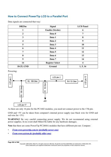
- Page 502 and 503: Traceroute Document revision 1.2 (F
- Page 504 and 505: ICMP Bandwidth Test Document revisi
- Page 506 and 507: System Resource Management Document
- Page 508 and 509: IRQ Usage Monitor Command name: /sy
- Page 510 and 511: 7 00:0e.0 Atheros Communications AR
- Page 512 and 513: [admin@Gateway] system clock> print
- Page 516 and 517: [admin@MikroTik] system lcd> print
- Page 518 and 519: Support Output File Document revisi
- Page 520 and 521: SSH (Secure Shell) Server and Clien
- Page 522 and 523: SSH Client Command name: /system ss
- Page 524 and 525: General Information Command name: /
- Page 526 and 527: • http://www.ctsystems.org/rs.htm
- Page 528 and 529: To connect to a device connected to
- Page 530 and 531: • Precise Positioning Service (PP
- Page 532 and 533: Scripting Host and Complementary To
- Page 534 and 535: License required: level1 Home menu
- Page 536 and 537: [admin@MikroTik] ip address> /user
- Page 538 and 539: * - multiplication. Binary operator
- Page 540 and 541: [admin@MikroTik] interface> :put (~
- Page 542 and 543: Local Variables g1=this is global v
- Page 544 and 545: In the example below monitor action
- Page 546 and 547: Home menu level: /system script job
- Page 548 and 549: Specifications Packages required: s
- Page 550 and 551: [admin@MikroTik] system script> ..
- Page 552 and 553: Specifications Packages required: a
- Page 554 and 555: In the following example we will ad
- Page 556 and 557: Packages required: ups License requ
- Page 558 and 559: Runtime Calibration Command name: /
- Page 560 and 561: NTP (Network Time Protocol) Documen
- Page 562 and 563: • synchronized - local clock is s
- Page 564 and 565:
RouterBoard-specific functions Docu
- Page 566 and 567:
Firmware upgrade can take up to 20s
- Page 568 and 569:
LED Managment Command name: :led De
- Page 570 and 571:
License Management Document revisio
- Page 572 and 573:
can not move license on another har
- Page 574 and 575:
• ERROR: Key for specified softwa
- Page 576 and 577:
MikroTik RouterOS implements indust
- Page 578 and 579:
Router has several global configura
- Page 580:
Notes print command has the followi