PT-19 ARF Assembly Manual - E-flite
PT-19 ARF Assembly Manual - E-flite
PT-19 ARF Assembly Manual - E-flite

Create successful ePaper yourself
Turn your PDF publications into a flip-book with our unique Google optimized e-Paper software.
9. Slide a #4 washer on a 4-40 x 1/2-inch socket<br />
head screw. Prepare two of these to secure the tail<br />
to the fuselage.<br />
Required Parts<br />
Rudder Servo Installation<br />
CL Option<br />
<br />
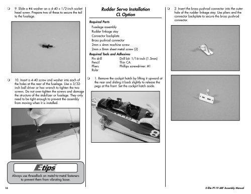
2. Insert the brass pushrod connector into the outer<br />
hole of the rudder linkage stay. Use pliers and the<br />
connector backplate to secure the brass pushrod<br />
connector.<br />
Fuselage assembly<br />
Rudder linkage stay<br />
Connector backplate<br />
Brass pushrod connector<br />
2mm x 4mm machine screw<br />
2mm x 8mm sheet metal screw (2)<br />
Required Tools and Adhesives<br />
Pin drill<br />
Drill bit: 1/16-inch (1.5mm)<br />
Pencil<br />
Thin CA<br />
Pliers Phillips screwdriver: #1<br />
Ruler<br />
<br />
10. Insert a 4-40 screw and washer into each of<br />
the holes at the rear of the fuselage. Use a 3/32-<br />
inch ball driver or hex wrench to tighten the two<br />
screws. Do not over-tighten the screws and damage<br />
the structure of the stabilizer or fuselage. They only<br />
need to be tight enough to prevent the assembly<br />
from moving when it is installed.<br />
<br />
1. Remove the cockpit hatch by lifting it upward at<br />
the rear and sliding it back slightly to release the<br />
pegs at the front. Set the cockpit hatch aside.<br />
Always use threadlock on metal-to-metal fasteners<br />
to prevent them from vibrating loose.<br />
16 E-<strong>flite</strong> <strong>PT</strong>-<strong>19</strong> <strong>ARF</strong> <strong>Assembly</strong> <strong>Manual</strong>