PT-19 ARF Assembly Manual - E-flite
PT-19 ARF Assembly Manual - E-flite
PT-19 ARF Assembly Manual - E-flite

You also want an ePaper? Increase the reach of your titles
YUMPU automatically turns print PDFs into web optimized ePapers that Google loves.
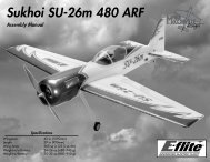
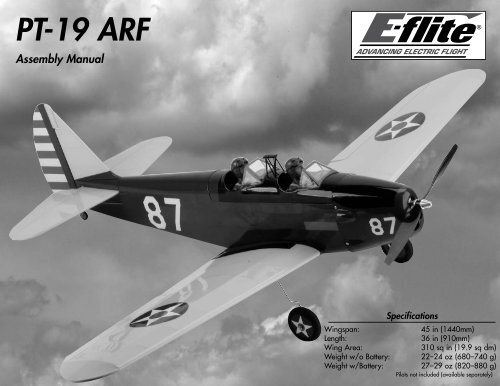
<strong>PT</strong>-<strong>19</strong> <strong>ARF</strong><br />
<strong>Assembly</strong> <strong>Manual</strong><br />
Specifications<br />
Wingspan:<br />
45 in (1440mm)<br />
Length:<br />
36 in (910mm)<br />
Wing Area:<br />
310 sq in (<strong>19</strong>.9 sq dm)<br />
Weight w/o Battery: 22–24 oz (680–740 g)<br />
Weight w/Battery: 27–29 oz (820–880 g)<br />
Pilots not included (available separately)
Table of Contents<br />
Introduction................................................................ 2<br />
Important Information Regarding<br />
Warranty Information............................................ 2<br />
Using the <strong>Manual</strong>....................................................... 2<br />
Contents of Kit/Parts Layout........................................ 2<br />
Covering Colors......................................................... 2<br />
Recommended Radio Equipment,<br />
Radio Controlled Version....................................... 3<br />
Recommended Equipment, Control Line Version............ 3<br />
Optional Accessories.................................................. 3<br />
Brushless Outrunner Setup........................................... 3<br />
Required Tools and Adhesives..................................... 3<br />
Note on Lithium Polymer Batteries................................ 3<br />
Warning.................................................................... 4<br />
Construction Options.................................................. 4<br />
Fixed Aileron Linkage Installation CL Option................. 4<br />
Aileron Servo and Linkage Installation RC Option......... 6<br />
Joining the Wing Panels, RC and CL Options............. 10<br />
Landing Gear Installation RC/CL options.................... 13<br />
Stabilizer and Fin Installation RC/CL Options............. 14<br />
Rudder Servo Installation CL Option........................... 16<br />
Rudder Servo Installation RC Option.......................... 18<br />
Elevator Bellcrank Installation CL Option..................... 20<br />
Elevator Servo Installation RC Option......................... 22<br />
Receiver Installation RC Option.................................. 24<br />
Speed Control Installation, RC/CL Options................. 25<br />
Motor Installation RC/CL Options.............................. 26<br />
Cowling and Propeller Installation,<br />
RC/CL Options.................................................... 27<br />
Motor Battery Placement RC/CL Options.................... 30<br />
Wing Installation, RC/CL Options.............................. 31<br />
Leadout Guide Installation and Tip<br />
Weight Box CL Option......................................... 31<br />
Pilot Installation (Optional) RC/CL Options................. 33<br />
Control Throws......................................................... 33<br />
Center of Gravity...................................................... 34<br />
Preflight................................................................... 34<br />
Range Test Your Radio............................................... 35<br />
Control Line Flying Checklist...................................... 35<br />
Safety, Precautions and Warnings.............................. 38<br />
Safety Do’s and Don’ts for Pilots................................ 38<br />
Warranty Information............................................... 39<br />
Instructions for Disposal of WEEE by<br />
Users in the European Union................................ 40<br />
2008 Official Academy of Model<br />
Aeronautics Safety Code...................................... 40<br />
Building and Flying Notes................................... 42–43<br />
Introduction<br />
During WWII, the <strong>PT</strong>-<strong>19</strong> Cornell was one of the<br />
primary training aircraft for the Army Air Corps. The<br />
<strong>PT</strong>-<strong>19</strong> had a higher wing loading and higher stall<br />
speed that helped pilots in training learn more than the<br />
current biplane trainers.<br />
E-<strong>flite</strong>’s version of the <strong>PT</strong>-<strong>19</strong> is a scale, almost-readyto-fly,<br />
electric model designed for radio control with<br />
the option of control line. It’s 90% pre-built out of the<br />
box and boasts an appealing USAAC trim scheme for<br />
a great scale appearance. Those modelers who enjoy<br />
radio controlled flying can complete this <strong>ARF</strong> with the<br />
recommended E-<strong>flite</strong> ® Park 450 or high-powered Park<br />
480 motor. The <strong>PT</strong>-<strong>19</strong> features an easily accessible<br />
magnetic battery hatch and steerable tail wheel for<br />
improved ground handling.<br />
The <strong>PT</strong>-<strong>19</strong> can also be flown as a control line plane.<br />
All of the internal control line completion hardware is<br />
included, while the ESC timer, wooden control handle<br />
and spool of wire cable is available separately.<br />
Control line flying will allow the airplane to be flown<br />
by two cables that connect the model to the operator<br />
through the optional control line handle and allow the<br />
operator’s hand movement to guide the model.<br />
Either way you choose, the flying options are yours<br />
with the E-<strong>flite</strong> <strong>PT</strong>-<strong>19</strong>.<br />
Important Information<br />
Regarding Warranty Information<br />
Please read our Warranty and Liability Limitations<br />
section on Page 39 before building this product. If you<br />
as the Purchaser or user are not prepared to accept the<br />
liability associated with the use of this Product, you are<br />
advised to return this Product immediately in new and<br />
unused condition to the place of purchase.<br />
Using the <strong>Manual</strong><br />
This manual is divided into sections to help make<br />
assembly easier to understand, and to provide breaks<br />
between each major section. In addition, check boxes<br />
have been placed next to each step to keep track<br />
of its completion. Steps with a single circle () are<br />
performed once, while steps with two circles ( )<br />
indicate that the step will require repeating, such as for<br />
a right or left wing panel, two servos, etc.<br />
Remember to take your time and follow the directions.<br />
Contents of Kit/Parts Layout<br />
Replacement Parts<br />
EFL2676<br />
EFL2677<br />
EFL2678<br />
EFL2679<br />
EFL2680<br />
EFL2681<br />
EFL2682<br />
EFL2683<br />
EFL2684<br />
EFL2685<br />
EFLA2<strong>19</strong><br />
HANU872<br />
HANU885<br />
Wing Set<br />
Fuselage Set<br />
Tail Set<br />
Cowling<br />
Landing Gear<br />
Pushrod Set<br />
Fuselage Hacth<br />
Windscreens<br />
C/L Bellcrank <strong>Assembly</strong><br />
Hardware Package<br />
Tailwheel <strong>Assembly</strong><br />
Covering Colors<br />
Bright Yellow<br />
Midnight Blue<br />
2 E-<strong>flite</strong> <strong>PT</strong>-<strong>19</strong> <strong>ARF</strong> <strong>Assembly</strong> <strong>Manual</strong>
Recommended Radio Equipment,<br />
Radio Controlled Version<br />
You will need a minimum of a 4-channel transmitter,<br />
receiver and four servos. You can choose to purchase<br />
a complete radio system. If you are using an<br />
existing transmitter, just purchase the other required<br />
equipment separately. We recommend the crystalfree,<br />
interference-free Spektrum DX5e 2.4GHz DSM ®<br />
5-channel system. If using your own transmitter, we<br />
recommend the E-<strong>flite</strong> S75 Sub-Micro servos.<br />
If you own a Spektrum radio, just add a DSM2 <br />
receiver and four E-<strong>flite</strong> S75 Sub-Micro servos. We<br />
show the installation of the AR6100 receiver in the<br />
manual.<br />
Radio System<br />
SPM5500 DX5e DSM2 5CH system<br />
Or Purchase Separately<br />
any of the Following Receivers<br />
SPMAR500 AR500 DSM2 5-Channel Full-<br />
Range Receiver (for DX5e, DX6i<br />
or DX7)<br />
SPMAR6100 AR6100 DSM2 6-Channel Park<br />
Flyer Receiver (for DX5e, DX6i,<br />
or DX7)<br />
SPMAR6100E AR6100E DSM2 6-Channel Park<br />
Flyer Receiver (for DX5e, DX6i,<br />
or DX7)<br />
SPMAR6200 AR6200 DSM2 6-Channel Full<br />
Range Receiver (for DX5e, DX6i,<br />
or DX7)<br />
And<br />
EFLRS75<br />
7.5-gram Sub-Micro<br />
Servo (4)<br />
EFLREX6L 6-inch Extension, Lightweight (2)<br />
EFLRYH3<br />
3-inch Y-harness, Lightweight<br />
EFLA170<br />
EFLA171<br />
EFLA172<br />
SIGSH561<br />
Recommended Equipment,<br />
Control Line Version<br />
Control Line Handle<br />
52’ Braided Steel Lines<br />
Control Line Motor Timer<br />
Sig Mfg Lead Balancing<br />
Weight (1/4 ounce)<br />
Optional Accessories<br />
EFLA110 Power Meter<br />
EFLC3005 Celectra 1- to 3-Cell<br />
Li-Po Charger<br />
EFLC505<br />
Intelligent 1- to 5-Cell<br />
Balancing Charger<br />
EFLA150 Military Pilot (1 or 2)<br />
EFLM1400<br />
Brushless Outrunner Setup<br />
APC10070E<br />
EFLP1080E<br />
EFLA1030<br />
or<br />
EFLM1505<br />
APC12060E<br />
EFLA1040L<br />
and<br />
EFLA172<br />
EFLB21003S<br />
Park 450 Brushless Outrunner<br />
Motor, 890Kv<br />
10x7 Electric Propeller<br />
10X8 Electric Propeller<br />
30-Amp Pro Switch-Mode<br />
BEC Brushless ESC<br />
Park 480 Brushless Outrunner<br />
Motor, 1020Kv<br />
12x6 Electric Propeller<br />
40-Amp Lite Pro Switch-Mode<br />
BEC Brushless<br />
Motor Timer (control line only)<br />
2100mAh 3S 11.1V 20C Li-Po,<br />
13AWG EC3<br />
Required Tools and Adhesives<br />
Tools & Equipment<br />
Card stock Epoxy brushes<br />
Low-tack tape Medium grit sandpaper<br />
Mixing cups Mixing sticks<br />
Paper towels Pencil<br />
Pin drill<br />
Pliers<br />
Rubbing alcohol Ruler<br />
Scissors<br />
Square<br />
String/dental floss T-pins<br />
Trim seal tool Phillips screwdriver: #0, #1<br />
Felt-tipped pen Rubber bands (optional)<br />
Heat gun Sealing iron<br />
Hobby knife (#11 blade)<br />
Nut driver: 1/4-inch, 5.5mm<br />
Hex wrench or ball driver: 1.5mm, 3/32-inch<br />
Drill bit: 1/16-inch (1.5mm), 1/8-inch (3mm)<br />
Adhesives<br />
Threadlock 30-Minute Epoxy (HAN8002)<br />
Thin CA<br />
6-Minute Epoxy (HAN8000)<br />
Note on Lithium Polymer Batteries<br />
Lithium Polymer batteries are significantly<br />
more volatile than alkaline or Ni-Cd/<br />
Ni-MH batteries used in RC applications.<br />
All manufacturer’s instructions and warnings<br />
must be followed closely. Mishandling of<br />
Li-Po batteries can result in fire. Always<br />
follow the manufacturer’s instructions when<br />
disposing of Lithium Polymer batteries.<br />
The Spektrum trademark is used with permission<br />
of Bachmann Industries, Inc.<br />
E-<strong>flite</strong> <strong>PT</strong>-<strong>19</strong> <strong>ARF</strong> <strong>Assembly</strong> <strong>Manual</strong><br />
3
Warning<br />
An RC aircraft is not a toy! If misused, it can cause<br />
serious bodily harm and damage to property. Fly<br />
only in open areas, preferably at AMA (Academy of<br />
Model Aeronautics) approved flying sites, following all<br />
instructions included with your radio.<br />
Keep loose items that can get entangled in the<br />
propeller away from the prop, including loose clothing,<br />
or other objects such as pencils and screwdrivers.<br />
Especially keep your hands away from the propeller.<br />
During the course of building your <strong>PT</strong>-<strong>19</strong> <strong>ARF</strong> we<br />
suggest that you use a soft base for the building<br />
surface. Such things as a foam stand, large piece of<br />
bedding foam or a thick bath towel will work well and<br />
help protect the model from damage during assembly.<br />
Construction Options<br />
Your <strong>PT</strong>-<strong>19</strong> can be built a variety of ways. The two<br />
different options are either Radio Control (RC) or<br />
Control Line (CL). The RC version has the ability to<br />
be transformed from RC to CL and back to RC again<br />
with only a few minutes of work. For those who would<br />
like to built the model soley as a CL model, you will<br />
find a section dedicated to this in the beginning of<br />
construction when installing the aileron linkages. You<br />
will find in bold print at each section, what version it<br />
is for. Either RC or CL will determine what the step is<br />
for. Please note that there is a section at the end of the<br />
manual as to what is required to lock the ailerons in<br />
place for CL flying if you have built the RC version.<br />
Fixed Aileron Linkage Installation<br />
CL Option<br />
Required Parts<br />
Wing panel (left and right)<br />
Aileron pushrod wire, 2 1 / 2 -inch (65mm) (2)<br />
Control line servo cover (left and right)<br />
Brass pushrod connector (2)<br />
Pushrod connector backplate (2)<br />
2mm x 4mm machine screw (2)<br />
2mm x 8mm sheet metal screw (8)<br />
Required Tools and Adhesives<br />
Phillips screwdriver: #1 Pliers<br />
Low-tack tape<br />
This section details the installation of the aileron<br />
linkage for the control line version of the<br />
<strong>PT</strong>-<strong>19</strong>. If you are building the radio controlled<br />
version, please skip to the next section.<br />
1. Remove the aileron servo cover from the wing<br />
and set it aside. You will be using a different cover,<br />
but you may want to save this cover for use later if<br />
you convert your aircraft to radio control.<br />
2. Insert the end of the 2 1 / 2 -inch (65mm) aileron<br />
linkage in the outside hole of the aileron control horn.<br />
4 E-<strong>flite</strong> <strong>PT</strong>-<strong>19</strong> <strong>ARF</strong> <strong>Assembly</strong> <strong>Manual</strong>
3. Remove the string from the bottom of the wing<br />
and tape it inside the wing. You may want to<br />
convert you <strong>PT</strong>-<strong>19</strong> to radio control at some time,<br />
and the string will be helpful in pulling the servo<br />
extension from the aileron servo through the wing<br />
when you do.<br />
6. Slide the aileron pushrod through the hole in the<br />
brass pushrod connector.<br />
5. Use a #1 Phillips screwdriver and four 2mm x<br />
8mm sheet metal screws to secure the aileron servo<br />
cover to the wing.<br />
7. Use a small piece of low-tack tape to hold the<br />
aileron centered for the next step.<br />
4. Locate the aileron cover for the control line<br />
version of your model. Insert the brass pushrod<br />
connector into the outside hole of the control line<br />
aileron servo cover. Use a pushrod connector<br />
backplate and pliers to secure the connector.<br />
E-<strong>flite</strong> <strong>PT</strong>-<strong>19</strong> <strong>ARF</strong> <strong>Assembly</strong> <strong>Manual</strong><br />
5
8. Use a #1 Phillips screwdriver and a 2mm x 4mm<br />
machine screw to secure the aileron pushrod wire.<br />
Remove the low-tack tape from the aileron at this<br />
time as well.<br />
<br />
9. Repeat steps 1 through 8 to install the remaining<br />
cover and aileron linkage.<br />
Aileron Servo and Linkage Installation<br />
RC Option<br />
Required Parts<br />
Radio system Wing panel (left and right)<br />
Servo (2)<br />
Connector backplate (2)<br />
Brass pushrod connector (2)<br />
2mm x 4mm machine screw (2)<br />
2mm x 8mm sheet metal screw (8)<br />
6-inch (152mm) servo extension (2)<br />
Aileron pushrod wire, 2 1 / 2 -inch (65mm) (2)<br />
Required Tools and Adhesives<br />
Pin drill<br />
Drill bit: 1/16-inch (1.5mm)<br />
Pencil Phillips screwdriver: #0, #1<br />
6-minute epoxy Medium grit sandpaper<br />
Mixing cup Mixing stick<br />
Thin CA<br />
String/dental floss<br />
Pliers<br />
Low-tack tape<br />
This section details the installation of the aileron<br />
linkage for the radio controlled version of the<br />
<strong>PT</strong>-<strong>19</strong>. If you are building the control line version<br />
and have already installed the aileron linkage,<br />
please skip this section of the manual.<br />
2. Use a pin drill and 1/16-inch (1.5mm) drill bit<br />
to enlarge the center outer hole of the servo arm<br />
as shown.<br />
3. Insert the brass pushrod connector into the hole.<br />
Use pliers and the connector backplate to secure<br />
the brass pushrod connector to the servo arm.<br />
<br />
1. Use the radio system to center the aileron servos.<br />
Use a #0 Phillips screwdriver to remove the control<br />
horns and install them on the servos as shown.<br />
Prepare a left and right aileron servo at this time.<br />
6 E-<strong>flite</strong> <strong>PT</strong>-<strong>19</strong> <strong>ARF</strong> <strong>Assembly</strong> <strong>Manual</strong>
5. Position the servo on the servo cover. Center the<br />
servo arm in the cutout in the servo cover<br />
as shown.<br />
7. Once the servo is properly positioned, use a<br />
pencil to trace the servo tabs and servo edges on<br />
the servo cover.<br />
4. Carefully remove the servo cover from the<br />
wing panel.<br />
6. The servo arm will also be flush with the edge of the<br />
servo cover as shown when it is positioned properly.<br />
8. Check to make sure the servo mounting block<br />
does not overhang the edge of the servo cover. If<br />
so, you will need to adjust the position of the servo<br />
to make sure both blocks will be on the servo cover.<br />
E-<strong>flite</strong> <strong>PT</strong>-<strong>19</strong> <strong>ARF</strong> <strong>Assembly</strong> <strong>Manual</strong><br />
7
9. Use a piece of medium grit sandpaper to<br />
roughen the ends of the servo mounting blocks.<br />
This will help the epoxy to adhere to the blocks<br />
and provide a more secure bond between the<br />
blocks and servo cover.<br />
12. Once the epoxy has fully cured, position the<br />
servo between the servo mounting blocks.<br />
14. Use a pin drill and 1/16-inch (1.5mm) drill<br />
bit to drill a hole in each mounting block at the<br />
position marked in the previous step.<br />
10. Mix a small amount of 6-minute epoxy. Use the<br />
epoxy to glue the blocks to the servo cover. Use the<br />
lines drawn on the servo cover to properly position<br />
the block.<br />
13. Use a pencil to mark the positions for the servo<br />
mounting screws onto the mounting blocks.<br />
15. Place 2–3 drops of thin CA into each of the<br />
holes to harden the surrounding wood. This will<br />
provide a harder surface for the screws to bite into<br />
and make them more secure when installed.<br />
<br />
11. Repeat the steps 2 through 10 to glue the<br />
blocks on the remaining servo cover at this time.<br />
Allow the epoxy to fully cure before proceeding.<br />
8 E-<strong>flite</strong> <strong>PT</strong>-<strong>19</strong> <strong>ARF</strong> <strong>Assembly</strong> <strong>Manual</strong>
16. Mount the servo to the blocks using the two<br />
screws provided with the servo. Use a #1 Phillips<br />
screwdriver to tighten the screws.<br />
18. Use string or dental floss to secure the<br />
extension to the servo lead so they do not<br />
become unplugged inside the wing.<br />
<strong>19</strong>. Remove the tape from the string near<br />
the aileron servo opening in the wing. Tie the<br />
string to the end of the aileron servo extension.<br />
Use the string to pull the extension through the<br />
wing and out of the hole near the center of the<br />
wing as shown.<br />
17. Connect a 6-inch (152mm) servo extension to<br />
the lead from the aileron servo.<br />
If using string or dental floss to secure your servo<br />
lead, we place a very small drop of thin CA onto<br />
the knot to ensure it does not untie over time.<br />
E-<strong>flite</strong> <strong>PT</strong>-<strong>19</strong> <strong>ARF</strong> <strong>Assembly</strong> <strong>Manual</strong><br />
9
20. Use a #1 Phillips screwdriver to install the four<br />
2mm x 8mm sheet metal screws that secure the<br />
aileron servo cover to the wing.<br />
22 Insert the aileron pushrod in the hole of the<br />
brass connector pushrod. Once the pushrod is<br />
inserted into the connector, center the aileron using<br />
low tack tape.<br />
Required Parts<br />
Joining the Wing Panels,<br />
RC and CL Options<br />
Wing panel (right and left) Wing joiner<br />
4-40 x 1-inch socket head screw (2) (optional)<br />
Required Tools and Adhesives<br />
30-minute epoxy Paper towel<br />
Mixing cup Mixing sticks<br />
Epoxy brush Rubbing alcohol<br />
T-pin<br />
Low-tack tape<br />
Square<br />
Pencil<br />
Sandpaper: medium grit<br />
Rubber bands (optional)<br />
21. Insert the Z-bend end of the 2 1 / 2 -inch (65mm)<br />
aileron linkage in the outside hole of the aileron<br />
control horn.<br />
23. Make sure the aileron servo is centered from<br />
Step 1. Use a #1 Phillips screwdriver and 2mm x<br />
4mm machine screw to secure the aileron pushrod<br />
in the brass pushrod connector. Once connected,<br />
remove the low tack tape from the aileron.<br />
<br />
1. Use a pencil to mark the wing panel and wing<br />
joiner. This is necessary as you will need to be able<br />
to return the joiner back to the panels in which it<br />
was fitted.<br />
<br />
24. Repeat steps 12 through 23 to mount the<br />
remaining aileron servo to the servo cover and<br />
install the aileron linkage.<br />
10 E-<strong>flite</strong> <strong>PT</strong>-<strong>19</strong> <strong>ARF</strong> <strong>Assembly</strong> <strong>Manual</strong>
2. Place the joiner on the work surface. With the<br />
square aligned with the high point of the joiner, use<br />
a pencil to make the centerline on the joiner.<br />
<br />
4. Place a T-pin lightly in the center of the joiner.<br />
This will allow the joiner to fit centered in each<br />
wing panel when installed.<br />
<br />
7. Apply epoxy to the end of the wing joiner that<br />
will be inserted into the wing panel. Make sure to<br />
cover the front, back, top and bottom of the joiner.<br />
<br />
3. Slide the joiner into the appropriate wing panel<br />
up to the line drawn in the previous step. If the<br />
joiner does not slide in easily, it may be necessary<br />
to lightly sand the joiner to correct the fit. Repeat<br />
the process to fit the joiner into both wing panels.<br />
<br />
5. Mix 1/2 ounce (15ml) of 30-minute epoxy and<br />
using an epoxy brush apply the epoxy to the root<br />
of one wing panel.<br />
8. Slide the joiner into the wing panel. Work slowly<br />
so the epoxy can be cleaned using a paper towel<br />
and rubbing alcohol as the joiner is inserted into<br />
the panel. Once the joiner is inserted, apply epoxy<br />
to all edges of the exposed joiner.<br />
<br />
6. Use a mixing stick to apply the epoxy into the<br />
joiner pocket of the wing panel.<br />
Excess epoxy will ooze out of the joiner pocket as<br />
the joiner is inserted. If it does not, you have not<br />
used enough epoxy. Repeat steps 6 and 7 to apply<br />
more epoxy to the joiner and into the joiner pocket.<br />
E-<strong>flite</strong> <strong>PT</strong>-<strong>19</strong> <strong>ARF</strong> <strong>Assembly</strong> <strong>Manual</strong><br />
11
9. Apply epoxy in the joiner pocket and root of the<br />
remaining wing panel.<br />
<br />
10. Slide the wing panels tightly together. Remove<br />
the T-pin from the joiner that was installed in Step<br />
4. Slide the wing panels tightly together. Again,<br />
work slowly to clean up any excess epoxy using a<br />
paper towel and rubbing alcohol.<br />
<br />
11. Use low-tack tape to hold the two wing panels<br />
together until the epoxy fully cures. Clean any<br />
excess epoxy from the wing panels using rubbing<br />
alcohol and a paper towel.<br />
You can use the two 4-40 x 1-inch socket head<br />
wing bolts and three rubber bands to hold the wings<br />
together while the epoxy cures. Simply insert the wing<br />
bolts half-way into the holes at the trailing edge and<br />
wrap a rubber band around the bolts on both the<br />
top and bottom of the wing. Use a third rubber band<br />
around the wing dowels. Always clean up any excess<br />
epoxy using a paper towel and rubbing alcohol.<br />
12 E-<strong>flite</strong> <strong>PT</strong>-<strong>19</strong> <strong>ARF</strong> <strong>Assembly</strong> <strong>Manual</strong>
Required Parts<br />
Landing Gear Installation<br />
RC/CL options<br />
Assembled wing<br />
Main landing gear assembly (2)<br />
Landing gear strap (4)<br />
2mm x 8mm sheet metal screw (8)<br />
Required Tools and Adhesives<br />
Phillips screwdriver: #1 Hex wrench: 1.5mm<br />
Hobby knife with #11 blade<br />
A 1.5mm allen wrench has been supplied for you in<br />
case you need to remove the wheels at any given time.<br />
1. Locate one of the pre-assembled main landing<br />
gear. There is not a right and left, so either one will<br />
work. Insert the landing gear into the pre-drilled<br />
hole in the landing gear block on the bottom of the<br />
wing. Press the gear into the block so it is flush with<br />
the bottom of the wing.<br />
You might find that sometimes the landing gear wire<br />
may not fully seat in the landing gear block. This is<br />
because of the radius on the bend of the wire. Use<br />
a small round file or #11 blade to remove a slight<br />
amount of material from the landing gear block<br />
allowing the wire gear to fully seat in the block.<br />
E-<strong>flite</strong> <strong>PT</strong>-<strong>19</strong> <strong>ARF</strong> <strong>Assembly</strong> <strong>Manual</strong><br />
13
2. Use two landing gear straps and four 2mm<br />
x 8mm sheet metal screws to secure the landing<br />
gear to the bottom of the wing. Use a #1 Phillips<br />
screwdriver to tighten the four screws.<br />
Stabilizer and Fin Installation<br />
RC/CL Options<br />
Required Parts<br />
Stabilizer assembly Vertical fin assembly<br />
#4 washer (4) 4-40 locknut (2)<br />
Fuselage<br />
4-40 x 1/2-inch socket head screw (2)<br />
Rudder pushrod wire, 18 3 / 8 -inch (467mm)<br />
Elevator pushrod wire, 20 1 / 2 -inch (521mm)<br />
<br />
3. Repeat Steps 1 and 2 to install the remaining<br />
main landing gear to the bottom of the wing.<br />
<br />
Required Tools and Adhesives<br />
Threadlock Nut driver: 1/4-inch<br />
Ball driver or hex wrench: 3/32-inch<br />
1. Locate the horizontal stabilizer and determine<br />
the top and bottom as shown in the photos below.<br />
The top will have the blind nuts, and the control<br />
horn will face to the bottom.<br />
<br />
2. Locate the vertical fin assembly. Slide the<br />
threaded rods from the fin through the holes in the<br />
stabilizer. The blind nuts in the stabilizer will fit into<br />
the recesses in the vertical fin fairing.<br />
14 E-<strong>flite</strong> <strong>PT</strong>-<strong>19</strong> <strong>ARF</strong> <strong>Assembly</strong> <strong>Manual</strong>
3. Slide a #4 washer onto each of the threaded<br />
rods exposed on the bottom of the stabilizer.<br />
<br />
5. Locate the 18 3 / 8 -inch (467mm) rudder pushrod.<br />
Insert the Z-bend in the pushrod into the center hole<br />
of the rudder control horn as shown.<br />
<br />
7. Insert the elevator and rudder pushrods into the<br />
pushrod tubes at the rear of the fuselage.<br />
4. Use a 1/4-inch nut driver to install a 4-40<br />
locknut on each of the threaded rods. Do not overtighten<br />
the nuts and damage the structure of the<br />
stabilizer. They only need to be tight enough to<br />
prevent the fin from moving when it is installed.<br />
<br />
6. Locate the 20 1 / 2 -inch (521mm) elevator<br />
pushrod. Insert the Z-bend in the pushrod into the<br />
center hole of the elevator control horn as shown.<br />
<br />
8. Slide the tail assembly forward so it is resting in<br />
position at the rear of the fuselage as shown below.<br />
E-<strong>flite</strong> <strong>PT</strong>-<strong>19</strong> <strong>ARF</strong> <strong>Assembly</strong> <strong>Manual</strong><br />
15
9. Slide a #4 washer on a 4-40 x 1/2-inch socket<br />
head screw. Prepare two of these to secure the tail<br />
to the fuselage.<br />
Required Parts<br />
Rudder Servo Installation<br />
CL Option<br />
<br />
2. Insert the brass pushrod connector into the outer<br />
hole of the rudder linkage stay. Use pliers and the<br />
connector backplate to secure the brass pushrod<br />
connector.<br />
Fuselage assembly<br />
Rudder linkage stay<br />
Connector backplate<br />
Brass pushrod connector<br />
2mm x 4mm machine screw<br />
2mm x 8mm sheet metal screw (2)<br />
Required Tools and Adhesives<br />
Pin drill<br />
Drill bit: 1/16-inch (1.5mm)<br />
Pencil<br />
Thin CA<br />
Pliers Phillips screwdriver: #1<br />
Ruler<br />
<br />
10. Insert a 4-40 screw and washer into each of<br />
the holes at the rear of the fuselage. Use a 3/32-<br />
inch ball driver or hex wrench to tighten the two<br />
screws. Do not over-tighten the screws and damage<br />
the structure of the stabilizer or fuselage. They only<br />
need to be tight enough to prevent the assembly<br />
from moving when it is installed.<br />
<br />
1. Remove the cockpit hatch by lifting it upward at<br />
the rear and sliding it back slightly to release the<br />
pegs at the front. Set the cockpit hatch aside.<br />
Always use threadlock on metal-to-metal fasteners<br />
to prevent them from vibrating loose.<br />
16 E-<strong>flite</strong> <strong>PT</strong>-<strong>19</strong> <strong>ARF</strong> <strong>Assembly</strong> <strong>Manual</strong>
3. Center the rudder linkage stay over the opening<br />
in the servo tray inside the fuselage with the<br />
pushrod connector toward the tail of the fuselage.<br />
Use a pencil to mark the positions for the servo<br />
mounting screws onto the servo tray.<br />
<br />
5. Place 2–3 drops of thin CA into each of the<br />
holes to harden the surrounding wood. This will<br />
provide a harder surface for the screws to bite into<br />
and make them more secure when installed.<br />
<br />
7. Position the rudder so there is a small amount<br />
of offset to the rudder as shown. This is necessary<br />
as the model will fly in a counterclockwise rotation<br />
and needs right rudder for the offset. The amount<br />
of offset is not extremely critical for the <strong>PT</strong>-<strong>19</strong>.<br />
Measuring at approximately 3/8–1/2 inch of<br />
right offset will deliver a nice strong pull during<br />
flight without any bad tendencies during basic<br />
maneuvering.<br />
<br />
4. Remove the rudder servo. Use a pin drill<br />
and 1/16-inch (1.5mm) drill bit to drill a hole<br />
in the servo tray at the position marked in the<br />
previous step.<br />
<br />
6. Mount the rudder linkage stay to the servo tray<br />
using two 2mm x 8mm sheet metal screws. Use a<br />
#1 Phillips screwdriver to tighten the screws. Slide<br />
the pushrod into the pushrod connector at this time.<br />
We recommend 1/2 inch rudder offset for your<br />
first flights if you have not flown CL before or it<br />
has been a long time since that last flight. You can<br />
reduce this over time to meet the personalized<br />
feel and performance of your <strong>PT</strong>-<strong>19</strong>.<br />
E-<strong>flite</strong> <strong>PT</strong>-<strong>19</strong> <strong>ARF</strong> <strong>Assembly</strong> <strong>Manual</strong><br />
17
8. Use a #1 Phillips screwdriver and 2mm x 4mm<br />
machine screw to secure the rudder pushrod in the<br />
brass pushrod connector.<br />
Required Parts<br />
Rudder Servo Installation<br />
RC Option<br />
Rudder servo Brass pushrod connector<br />
Fuselage assembly Connector backplate<br />
Radio system<br />
2mm x 4mm machine screw<br />
Required Tools and Adhesives<br />
Pin drill<br />
Drill bit: 1/16-inch (1.5mm)<br />
Pencil<br />
Thin CA<br />
Pliers Phillips screwdriver: #1<br />
Ruler<br />
<br />
2. Plug the rudder servo into the receiver. Power<br />
up the receiver and transmitter to center the rudder<br />
servo. Make sure the rudder trim at the radio<br />
has been centered and the end points (if using a<br />
computer radio) have been set to 100%. Use a pin<br />
drill and 1/16-inch (1.5mm) drill bit to enlarge the<br />
center outer hole of the servo arm as shown.<br />
<br />
1. Remove the cockpit hatch by lifting it upward at<br />
the rear and sliding it back slightly to release the<br />
pegs at the front. Set the cockpit hatch aside.<br />
<br />
3. Insert the brass pushrod connector into the hole<br />
drilled in the previous step. Use pliers and the<br />
connector backplate to secure the brass pushrod<br />
connector to the servo arm.<br />
18 E-<strong>flite</strong> <strong>PT</strong>-<strong>19</strong> <strong>ARF</strong> <strong>Assembly</strong> <strong>Manual</strong>
4. Insert the rudder servo into the opening in the<br />
servo tray inside the fuselage with the output shaft<br />
toward the tail of the fuselage. Use a pencil to<br />
mark the positions for the servo mounting screws<br />
onto the servo tray.<br />
<br />
6. Place 2–3 drops of thin CA into each of the<br />
holes to harden the surrounding wood. This will<br />
provide a harder surface for the screws to bite into<br />
and make them more secure when installed.<br />
<br />
8. Use a ruler placed against the rudder and fin to<br />
align the rudder with the fin.<br />
<br />
5. Remove the rudder servo. Use a pin drill<br />
and 1/16-inch (1.5mm) drill bit to drill a hole<br />
in the servo tray at the position marked in the<br />
previous step.<br />
<br />
7. Mount the servo to the servo tray using the two<br />
screws provided with the servo. Use a #1 Phillips<br />
screwdriver to tighten the screws. Slide the pushrod<br />
into the pushrod connector at this time.<br />
<br />
9. Check to make sure the rudder servo is<br />
centered using the radio system. Use a #1<br />
Phillips screwdriver and 2mm x 4mm machine<br />
screw to secure the rudder pushrod in the brass<br />
pushrod connector.<br />
E-<strong>flite</strong> <strong>PT</strong>-<strong>19</strong> <strong>ARF</strong> <strong>Assembly</strong> <strong>Manual</strong><br />
<strong>19</strong>
Elevator Bellcrank Installation<br />
CL Option<br />
Required Parts<br />
Wing assembly Fuselage assembly<br />
#4 washer (4) Brass pushrod connector<br />
4-40 x 1/2-inch socket head screw (4)<br />
Connector backplate<br />
2mm x 4mm machine screw<br />
Elevator bellcrank assembly<br />
Required Tools and Adhesives<br />
Hobby knife with #11 blade<br />
Pliers<br />
Nut driver: 5.5mm<br />
Ruler Phillips screwdriver: #1<br />
Felt-tipped pen Trim seal iron<br />
This section details the installation of the elevator<br />
bellcrank for the control line version of the <strong>PT</strong>-<strong>19</strong>.<br />
If you are building the radio controlled version,<br />
please skip to the next section. If you plan on<br />
using your model for both RC and CL, then you<br />
will want to perform the steps in this section.<br />
<br />
2. Use a trim seal iron to iron the covering at the<br />
fuselage and wing tip to create a finished look to<br />
your model.<br />
<br />
<br />
3. Use a felt-tipped pen to mark the top of the<br />
elevator bellcrank as shown. This is necessary<br />
as the bellcrank must be disassembled to fit into<br />
the fuselage and returned to its proper position<br />
when reassembled.<br />
4. Use a 5.5mm nut driver to remove the nut from<br />
the bellcrank assembly. Remove the flanged washer<br />
and bellcrank from the bellcrank assembly base.<br />
Place all items aside for later.<br />
<br />
1. Use a hobby knife with a new #11 blade to cut<br />
a slit in the covering on the left side of the fuselage<br />
for the elevator leadout wires to exit. Also cut a slit<br />
in the left wing tip for the leadout wire guide to fit<br />
into the wing.<br />
20 E-<strong>flite</strong> <strong>PT</strong>-<strong>19</strong> <strong>ARF</strong> <strong>Assembly</strong> <strong>Manual</strong>
5. Use four 4-40 x 1/2-inch socket head screws<br />
and four #4 washers to secure the bellcrank base<br />
inside the fuselage. Note that the threaded stud for<br />
the bellcrank is facing the slot in the fuselage for<br />
the leadout wires.<br />
<br />
7. Insert the brass pushrod connector into the<br />
hole in the elevator bellcrank. Use pliers and the<br />
connector backplate to secure the brass pushrod<br />
connector to the elevator bellcrank.<br />
<br />
8. Carefully inspect the flanged washer. Is must be<br />
installed in the correct direction for the bellcrank to<br />
operate smoothly. The narrow part of the flange will<br />
fit against the bearing in the bellcrank, and the wide<br />
edge faces the nut holding the assembly together.<br />
<br />
6. Slide the elevator bellcrank into the fuselage<br />
through the slot exposed in Step 1.<br />
<br />
9. Slide the bellcrank onto the threaded stud. Make<br />
sure the mark made in Step 3 is facing up. Slide<br />
the flanged washer onto the threaded stud (not the<br />
correct direction as described in the previous step)<br />
and use the nut and 5.5mm nut driver to tighten the<br />
nut. Snug the nut down to prevent damage to the<br />
bearing in the bellcrank. Insert the elevator pushrod<br />
into the hole in the brass pushrod connector.<br />
You will note in the pictures we have installed<br />
the pushrod connector in the inner hole on the<br />
bellcrank. This will provide good solid control inputs<br />
for your first flights. Later on, you may move to the<br />
outside hole for even more throw if you so wish.<br />
E-<strong>flite</strong> <strong>PT</strong>-<strong>19</strong> <strong>ARF</strong> <strong>Assembly</strong> <strong>Manual</strong><br />
21
10. Use a ruler placed against the stabilizer and<br />
elevator to align the stabilizer with the elevator.<br />
<br />
12. Use a #1 Phillips screwdriver and 2mm x 4mm<br />
machine screw to secure the elevator pushrod in<br />
the brass pushrod connector.<br />
Elevator Servo Installation<br />
RC Option<br />
Required Parts<br />
<br />
11. Align the elevator bellcrank with the center line<br />
of the fuselage.<br />
If you have opted to fly the <strong>PT</strong>-<strong>19</strong> as both a Control<br />
Line and Radio Control model you will need to<br />
remove the bellcrank at this time to prepare for<br />
the elevator servo installation as these two items<br />
are interchangeable and use the same mount.<br />
Elevator servo Brass pushrod connector<br />
Fuselage assembly Connector backplate<br />
4-40 x 1/2-inch socket head screw (4)<br />
#4 washer (4) Elevator servo tray<br />
Radio system<br />
2mm x 4mm machine screw<br />
Required Tools and Adhesives<br />
Pin drill<br />
Drill bit: 1/16-inch (1.5mm)<br />
Pencil<br />
Thin CA<br />
Pliers Phillips screwdriver: #1<br />
Ruler<br />
Hex wrench or ball driver: 3/32-inch<br />
This section details the installation of the elevator<br />
servo for the radio controlled version of the <strong>PT</strong>-<strong>19</strong>.<br />
If you are building the control line version and<br />
have installed the elevator bellcrank, please skip<br />
to the Motor Installation section of the manual.<br />
Please note the hardware to mount the bellcrank<br />
platform in the airplane is the same as used to<br />
mount the elevator servo plate in the airplane.<br />
<br />
1. Use a 3/32 inch hex wrench or ball driver to<br />
install four 4-40 x 1/2-inch socket head screws<br />
and four #4 washers to secure the elevator servo<br />
tray inside the fuselage. Note that the opening for<br />
the servo faces to the left side of the fuselage.<br />
22 E-<strong>flite</strong> <strong>PT</strong>-<strong>19</strong> <strong>ARF</strong> <strong>Assembly</strong> <strong>Manual</strong>
2. Plug the elevator servo into the receiver.<br />
Power up the receiver and transmitter to center<br />
the elevator servo. Make sure the elevator trim<br />
at the radio has been centered and the end<br />
points (if using a computer radio) have been set<br />
to 100%. Use a pin drill and 1/16-inch (1.5mm)<br />
drill bit to enlarge the center outer hole of the<br />
servo arm as shown.<br />
<br />
4. Insert the elevator servo into the opening in the<br />
servo tray inside the fuselage with the output the<br />
shaft toward the tail of the fuselage. Use a pencil<br />
to mark the positions for the servo mounting screws<br />
onto the servo tray.<br />
<br />
6. Place 2–3 drops of thin CA into each of the<br />
holes to harden the surrounding wood. This will<br />
provide a harder surface for the screws to bite into<br />
and make them more secure when installed.<br />
<br />
3. Insert the brass pushrod connector into the hole<br />
drilled in the previous step. Use pliers and the<br />
connector backplate to secure the brass pushrod<br />
connector to the servo arm.<br />
<br />
5. Remove the elevator servo. Use a pin drill<br />
and 1/16-inch (1.5mm) drill bit to drill a hole<br />
in the servo tray at the position marked in the<br />
previous step.<br />
<br />
7. Slide the pushrod into the brass connector and<br />
insert the servo into the servo tray. Mount the servo<br />
to the servo tray using the two screws provided<br />
with the servo. Use a #1 Phillips screwdriver to<br />
tighten the screws.<br />
E-<strong>flite</strong> <strong>PT</strong>-<strong>19</strong> <strong>ARF</strong> <strong>Assembly</strong> <strong>Manual</strong><br />
23
8. Use a ruler placed against the stabilizer and<br />
elevator to align the stabilizer with the elevator.<br />
Receiver Installation<br />
RC Option<br />
<br />
3. Position the receiver on the tray. The hook and<br />
loop tape will keep it secure.<br />
Required Parts<br />
Receiver<br />
Fuselage assembly<br />
Hook and loop tape<br />
Required Tools and Adhesives<br />
Scissors<br />
This section details the installation of the receiver<br />
for the radio controlled version of the <strong>PT</strong>-<strong>19</strong>. If you<br />
are building the control line version, please skip<br />
to the Motor Installation section of the manual.<br />
<br />
9. Check to make sure the elevator servo is<br />
centered using the radio system. Use a #1<br />
Phillips screwdriver and 2mm x 4mm machine<br />
screw to secure the elevator pushrod in the brass<br />
pushrod connector.<br />
<br />
1. Use scissors to cut a piece of hook and loop<br />
tape the size of your receiver. Apply one side of the<br />
tape to the receiver.<br />
<br />
4. Plug the rudder and elevator servos into the<br />
appropriate ports of the receiver. Tuck the servo<br />
leads as necessary so they will not interfere with<br />
the operation of the rudder and elevator functions<br />
of your aircraft.<br />
<br />
2. Apply the remaining side of the hook and loop<br />
tape from Step 1 to the radio tray as shown. This is<br />
done through the wing opening.<br />
24 E-<strong>flite</strong> <strong>PT</strong>-<strong>19</strong> <strong>ARF</strong> <strong>Assembly</strong> <strong>Manual</strong>
Required Parts<br />
Speed Control Installation,<br />
RC/CL Options<br />
Fuselage <strong>Assembly</strong> Speed control<br />
CL Timer (optional) Hook and loop tape<br />
Required Tools and Adhesives<br />
Scissors<br />
<br />
2. Apply the remaining side of the hook and<br />
loop tape from Step 1 to the inside of the fuselage<br />
as shown.<br />
<br />
4. You will need to plug the lead from the speed<br />
control into the receiver for the radio controlled<br />
version. Route the lead back and plug it into the<br />
throttle port of your receiver. If you are building the<br />
control line option you will plug the ESC into the<br />
CL Timer (EFLA172). This is shown in step 6 on the<br />
next page.<br />
<br />
We show the installation of the E-<strong>flite</strong> 30A and<br />
40A Pro SB ESC in the photos. We recommend<br />
the 40Amp Lite Pro SB ESC for the Park 480<br />
option. Either 40A ESC can be used. The 40A<br />
lite is mounted similar to the 30A ESC.<br />
1. Use scissors to cut a piece of hook and loop<br />
tape the size of your speed control. Apply one side<br />
of the tape to the speed control.<br />
<br />
3. Attach the speed control to the fuselage using<br />
the hook and loop tape.<br />
<br />
5. You will also need to mount the switch for the<br />
radio controlled version if using the 40-Amp<br />
controller. Use hook and loop material to place it in<br />
a convenient location inside the fuselage.<br />
E-<strong>flite</strong> <strong>PT</strong>-<strong>19</strong> <strong>ARF</strong> <strong>Assembly</strong> <strong>Manual</strong><br />
25
Important Information About Your Brushless ESC<br />
Make sure your ESC brake is programmed<br />
to Off. Also, be sure to use an ESC with the<br />
proper low-voltage cutoff and have it set<br />
correctly for the batteries you are using.<br />
6. For the control line version, you will need to<br />
install the motor timer. Use hook and loop tape<br />
to secure it inside the fuselage as shown. Make<br />
sure to locate it so it can be adjusted and<br />
activated easily.<br />
<br />
7. Route the motor leads from the speed control<br />
forward and through the opening in the fuselage<br />
as shown.<br />
<br />
Required Parts<br />
Motor Installation<br />
RC/CL Options<br />
Fuselage assembly<br />
#4 washer (4) Motor (Park 450 or 480)<br />
4-40 x 1/2-inch socket head screw (4)<br />
Required Tools and Adhesives<br />
Ball wrench or hex wrench: 3/32-inch<br />
Threadlock Phillips screwdriver: #1<br />
1. Attach the X-mount to your motor using the<br />
hardware provided with the motor and a #1<br />
Phillips screwdriver. Make sure to use threadlock on<br />
the screws to prevent them from vibrating loose.<br />
If flying control line it is common to program<br />
the ESC brake to On. The <strong>PT</strong>-<strong>19</strong> has been<br />
operated in either configuration successfully.<br />
26 E-<strong>flite</strong> <strong>PT</strong>-<strong>19</strong> <strong>ARF</strong> <strong>Assembly</strong> <strong>Manual</strong>
2. Attach your motor to the firewall using four<br />
4-40 x 1/2-inch socket head screws and four<br />
#4 washers. Tighten the screws using a 3/32-<br />
inch ball driver or hex wrench. Make sure to use<br />
threadlock on the four screws to prevent them from<br />
vibrating loose.<br />
<br />
3. Connect the leads from the motor and speed<br />
control at this time.<br />
Cowling and Propeller Installation,<br />
RC/CL Options<br />
Required Parts<br />
Fuselage assembly Cowling<br />
Propeller adapter Propeller<br />
2mm x 8mm sheet metal screw(4)<br />
Required Tools and Adhesives<br />
Card stock Low-tack tape<br />
Scissors<br />
Pin drill<br />
Thin CA Phillips screwdriver: #1<br />
Drill bit: 1/16-inch (1.5mm), 1/8-inch (3mm)<br />
<br />
1. Locate the cowl mounting plates inside the<br />
fuselage. There are two on each side. These plates<br />
reinforce the fuselage where the cowl mounting<br />
screws will be positioned.<br />
<br />
4. Check the operation of the motor at this time.<br />
It should rotate counterclockwise when viewed<br />
from the front of the aircraft. If not, follow the<br />
instructions provided with your speed control to<br />
correct the situation.<br />
The blind nuts in the fuselage for mounting the motor<br />
can be positioned for a variety of motors. Position the<br />
blind nuts so they are aligned with your particular<br />
motor before mounting the motor to the firewall.<br />
Never check the motor rotation on the bench<br />
with the propeller installed. The plane could<br />
move and cause serious injury. Always check the<br />
motor without the propeller to avoid injury.<br />
E-<strong>flite</strong> <strong>PT</strong>-<strong>19</strong> <strong>ARF</strong> <strong>Assembly</strong> <strong>Manual</strong><br />
27
2. Cut four strips of card stock that are 3/8-inch<br />
(9mm) wide and 4 inches (100mm) long.<br />
<br />
4. Place the cockpit hatch back into position on the<br />
top of the fuselage.<br />
<br />
6. Slide the propeller adapter onto the motor shaft.<br />
Use the adapter to help align the opening in the<br />
front of the cowl centered with the adapter and<br />
motor shaft.<br />
<br />
3. Use low-tack tape to attach a piece of card stock<br />
that will align with the front edge of the fuselage<br />
and with the cowl mounting plates that are inside<br />
the fuselage.<br />
<br />
5. Slide the cowling onto the front of the fuselage.<br />
Make sure the pieces of card stock are positioned<br />
on the outside of the cowl.<br />
28 E-<strong>flite</strong> <strong>PT</strong>-<strong>19</strong> <strong>ARF</strong> <strong>Assembly</strong> <strong>Manual</strong>
7. Once the opening in the cowl is centered with<br />
the adapter, use low-tack tape to hold the cowl in<br />
position on the front of the fuselage. Once tape<br />
has been applied, check the alignment before<br />
continuing to the next step.<br />
<br />
9. Remove the tape, card stock and cowl from the<br />
fuselage. Place 2–3 drops of thin CA into each of<br />
the holes to harden the surrounding wood. This will<br />
provide a harder surface for the screws to bite into<br />
and make them more secure when installed.<br />
<br />
11. Use a #1 Phillips screwdriver and four<br />
2mm x 8mm sheet metal screws to attach the<br />
cowl to the fuselage.<br />
<br />
8. Use a pin drill and 1/16-inch (1.5mm) drill bit<br />
to drill the four holes that will be used to secure the<br />
cowl with the cowl mounting screws.<br />
<br />
10. Use a pin drill and 1/8-inch (3mm) drill bit to<br />
enlarge the holes in the cowling.<br />
Important Information About Your Propeller<br />
It is very important to check to be sure the<br />
propeller is balanced before installing onto the<br />
shaft. An unbalanced propeller may strip the<br />
gears or cause poor flight characteristics.<br />
If it is necessary to enlarge the hole in<br />
the propeller or the spinner, make sure to<br />
check the balance of each afterwards.<br />
<br />
12. Slide the propeller onto the propeller adapter.<br />
E-<strong>flite</strong> <strong>PT</strong>-<strong>19</strong> <strong>ARF</strong> <strong>Assembly</strong> <strong>Manual</strong><br />
29
13. Thread the adapter nut on the adapter slightly.<br />
It does not need to hold the adapter at this time.<br />
Required Parts<br />
Motor Battery Placement<br />
RC/CL Options<br />
<br />
3. Place the opposite piece of hook and loop<br />
material on the battery tray. This will keep the<br />
battery from moving forward or rearward inside<br />
the fuselage during flight.<br />
Fuselage assembly Motor battery<br />
Battery strap Hook and loop tape<br />
Required Tools and Adhesives<br />
Scissors<br />
<br />
1. Locate the battery strap. Pass the strap under the<br />
battery tray inside the fuselage as shown.<br />
<br />
14. Slide the propeller and adapter onto the<br />
motor shaft. Tighten the adapter nut to secure the<br />
propeller to the motor shaft.<br />
<br />
4. Position the battery inside the fuselage. Use the<br />
battery strap to secure the battery so it does not<br />
come loose in flight.<br />
<br />
2. Cut a piece of hook and loop material and<br />
apply it to the motor battery as shown.<br />
The position of the battery can be adjusted to the<br />
front or rear of the fuselage as necessary to adjust the<br />
Center of Gravity when balancing the aircraft for flight.<br />
30 E-<strong>flite</strong> <strong>PT</strong>-<strong>19</strong> <strong>ARF</strong> <strong>Assembly</strong> <strong>Manual</strong>
Required Parts<br />
Wing Installation,<br />
RC/CL Options<br />
<br />
2. Plug the leads from the aileron servos into the<br />
Y-harness at this time when building the radio<br />
controlled version of the <strong>PT</strong>-<strong>19</strong>.<br />
Leadout Guide Installation and<br />
Tip Weight Box<br />
CL Option<br />
<br />
Fuselage assembly Wing assembly<br />
4-40 x 1-inch socket head bolts (2)<br />
#4 washer (2) Y-harness (RC only)<br />
Required Tools and Adhesives<br />
Ball driver of hex wrench: 3/32-inch<br />
1. Plug the Y-harness into the aileron port of the<br />
receiver if you are building the radio controlled<br />
version of the <strong>PT</strong>-<strong>19</strong>.<br />
<br />
3. Position the wing on the fuselage by inserting<br />
the dowels at the leading edge of the wing into<br />
the notches in the front of the wing saddle of<br />
the fuselage. Use a 3/32-inch ball driver or hex<br />
wrench to install the two 4-40 x 1-inch socket head<br />
bolts and two #4 washers that secure the wing to<br />
the fuselage.<br />
<br />
Required Parts<br />
Assembled airframe<br />
#4 washer 4-40 locknut<br />
Sig lead balancing weights, 1/4-ounce (3–4)<br />
Required Tools and Adhesives<br />
Pin drill<br />
Drill bit: 1/8-inch (3mm)<br />
Nut driver: 1/4-inch<br />
This section details the installation of the leadout<br />
guide and tip weight for the control line version.<br />
If you have built the radio controlled version<br />
you can skip this section of the manual.<br />
1. Use a pin drill and 1/8-inch (3mm) drill bit to<br />
drill the hole necessary to accept the threaded stud<br />
on the leadout guide.<br />
E-<strong>flite</strong> <strong>PT</strong>-<strong>19</strong> <strong>ARF</strong> <strong>Assembly</strong> <strong>Manual</strong><br />
31
2. Insert the leadout guide into the notch in the<br />
wing tip as shown.<br />
<br />
4. The leadout guide is attached to the wing using<br />
a #4 washer and 4-40 lock nut. Use a 1/4-inch<br />
nut driver to tighten the nut. Make sure not to overtighten<br />
the nut and crush the wing structure.<br />
In higher wind conditions you might find that 4<br />
lead weights work better. This is a personal flight<br />
preference. For new CL pilots we recommend 4<br />
weights in high wind environments (5–10 mph).<br />
<br />
3. Check to make sure the leadout wires are not<br />
crossed between the fuselage and leadout guide.<br />
If so, remove the guide and rotate it so the wires<br />
do not cross then insert it back into the slot in the<br />
wing tip.<br />
<br />
5. Use a 3/32 ball driver to open the tip weight<br />
box under the right wing tip. Insert 3/4 oz of<br />
weight into the box for the first control line flights.<br />
We use three Sig lead balancing weights (1/4 oz<br />
each) inside the box to laterally balance the model<br />
for control line flying.<br />
32 E-<strong>flite</strong> <strong>PT</strong>-<strong>19</strong> <strong>ARF</strong> <strong>Assembly</strong> <strong>Manual</strong>
Pilot Installation (Optional)<br />
RC/CL Options<br />
Required parts<br />
Battery hatch Military pilots (1 or 2)<br />
Tools and adhesives<br />
6-minute epoxy<br />
<br />
Control Throws<br />
1. Turn on the transmitter and receiver of your<br />
<strong>PT</strong>-<strong>19</strong> <strong>ARF</strong>. Check the movement of the rudder<br />
using the transmitter. When the stick is moved right,<br />
the rudder should also move right. Reverse the<br />
direction of the servo at the transmitter if necessary.<br />
<br />
1. If you are planning on installing scale pilots in<br />
your <strong>PT</strong>-<strong>19</strong>, now would be the best time to do so.<br />
They should be installed before balancing your<br />
aircraft as they could alter the center of gravity.<br />
<br />
2. Check the movement of the elevator with the<br />
radio system. Moving the elevator stick toward the<br />
bottom of the transmitter will make the airplane<br />
elevator move up.<br />
A small piece of foam rubber inserted after<br />
the weights are in place will keep them<br />
from rattling in the tip weight box.<br />
<br />
<br />
3. Check the movement of the ailerons with the<br />
radio system. Moving the aileron stick right will<br />
make the right aileron move up and the left aileron<br />
move down.<br />
4. Use a ruler to adjust the throw of the elevator,<br />
ailerons and rudder. Adjust the position of the<br />
pushrod at the control horn to achieve the<br />
following measurements when moving the sticks<br />
to their endpoints.<br />
E-<strong>flite</strong> <strong>PT</strong>-<strong>19</strong> <strong>ARF</strong> <strong>Assembly</strong> <strong>Manual</strong><br />
33
Aileron High Rate<br />
Up 1/2-inch (13mm)<br />
Down 1/2-inch (13mm)<br />
Aileron Low Rate<br />
Up 3/8-inch (10mm)<br />
Down 3/8-inch (10mm)<br />
Elevator High Rate<br />
Up 1/2-inch (13mm)<br />
Down 1/2-inch (13mm)<br />
Elevator Low Rate<br />
Up 3/8-inch (10mm)<br />
Down 3/8-inch (10mm)<br />
Rudder High Rate<br />
Up 1-inch (25mm)<br />
Down 1-inch (25mm)<br />
Rudder Low Rate<br />
Up 3/4-inch (<strong>19</strong>mm)<br />
Down 3/4-inch (<strong>19</strong>mm)<br />
Center of Gravity<br />
An important part of preparing the aircraft for flight is<br />
properly balancing the model.<br />
Caution: Do not inadvertently skip this step!<br />
The recommended Center of Gravity (CG) location for<br />
the <strong>PT</strong>-<strong>19</strong> <strong>ARF</strong> is 2 1 / 8 to 2 3 / 8 inches (54 to 60mm)<br />
back from the leading edge of the wing. Mark the<br />
location for the Center of Gravity on the top of the<br />
wing next to the fuselage as shown.<br />
When balancing your <strong>PT</strong>-<strong>19</strong> <strong>ARF</strong>, support the plane<br />
inverted at the marks made on the top of the wing with<br />
your fingers or a commercially available balancing<br />
stand. Adjust components as necessary so the model<br />
hangs level or slightly nose down. This is the correct<br />
balance point for your model. You might find you may<br />
be required to add a small amount of weight to either<br />
the front or back of the fuselage to achieve the correct<br />
balance.<br />
Check Your Radio<br />
Preflight<br />
Before going to the field, be sure that your batteries<br />
are fully charged per the instructions included with<br />
your radio. Charge both the transmitter and receiver<br />
pack for your airplane. Use the recommended charger<br />
supplied with your particular radio system, following<br />
the instructions provided with the radio. In most cases,<br />
the radio should be charged the night before going<br />
out flying.<br />
Before each flying session, be sure to range check your<br />
radio. See your radio manual for the recommended<br />
range and instructions for your radio system. Each<br />
radio manufacturer specifies different procedures for<br />
their radio systems. Next, start the motor. With the<br />
model securely anchored, check the range again.<br />
The range test should not be significantly affected. If<br />
it is, don’t attempt to fly! Have your radio equipment<br />
checked out by the manufacturer.<br />
Measurements are taken at the inner or<br />
widest point on the control surface.<br />
These are general guidelines measured from our own<br />
flight tests. You can experiment with higher rates to<br />
match your preferred style of flying.<br />
Travel Adjust, Sub Trim and Dual Rates are<br />
not listed and should be adjusted according<br />
to each individual model and preference.<br />
After the first flights, the CG position can be adjusted<br />
for your personal preference.<br />
Keep loose items that can get entangled in<br />
the propeller away from the prop. These<br />
include loose clothing, or other objects such<br />
as pencils and screwdrivers. Especially keep<br />
your hands away from the propeller.<br />
Double-check that all controls (aileron, elevator, rudder<br />
and throttle) move in the correct direction.<br />
Check the radio installation and make sure all the<br />
control surfaces are moving correctly (i.e. the correct<br />
direction and with the recommended throws). Test run<br />
the motor and make sure it transitions smoothly from<br />
off to full throttle and back. Also ensure the engine is<br />
installed according to the manufacturer’s instructions,<br />
and it will operate consistently.<br />
Check all the control horns, servo horns, and<br />
clevises to make sure they are secure and in good<br />
condition. Replace any items that would be considered<br />
questionable. Failure of any of these components in<br />
flight would mean the loss of your aircraft.<br />
34 E-<strong>flite</strong> <strong>PT</strong>-<strong>19</strong> <strong>ARF</strong> <strong>Assembly</strong> <strong>Manual</strong>
Range Test Your Radio<br />
1. Before each flying session, be sure to range<br />
check your radio. This is accomplished by turning<br />
on your transmitter with the antenna collapsed.<br />
Turn on the receiver in your airplane. With<br />
your airplane on the ground and the engine<br />
running, you should be able to walk 30 paces<br />
(approximately 100 feet) away from your airplane<br />
and still have complete control of all functions.<br />
If not, don’t attempt to fly! Have your radio<br />
equipment checked out by the manufacturer.<br />
2. Double-check that all controls (aileron, elevator,<br />
rudder and throttle) move in the correct direction.<br />
3. Be sure that your transmitter batteries are<br />
fully charged, per the instructions included with<br />
your radio.<br />
Control Line Flying Checklist<br />
If you are planning to fly your <strong>PT</strong>-<strong>19</strong> as a control line<br />
model you will need to accomplish a few items first<br />
to help ensure success during the first flight. With the<br />
model having the ability to be built in two different<br />
ways, Radio Control or Control Line, we have two<br />
sections dedicated to help you prepare the model.<br />
Control Line Built Model<br />
If you have constructed your model with the sole intent<br />
of flying it as a control line model, you need only add<br />
tip weight for flight.<br />
Be sure to place 3/4-ounce of tip weight in the tip<br />
weight box located under the right wing tip. This will<br />
help hold the model level and counter the weight of the<br />
lines. We use Sig 1/4 ounce tip weights (SIGSH561).<br />
These weights are available at your local hobby shop.<br />
You may vary the amount of weight at your discretion<br />
to fine-tune the flight qualities of your <strong>PT</strong>-<strong>19</strong>.<br />
Radio Control Built model<br />
If you have constructed your model with the main<br />
intent of RC flying, you can convert your model over to<br />
Control Line flying in just a few short minutes. You will<br />
need to lock the ailerons, set the rudder offset, add the<br />
tip weights, and swap out the elevator control system.<br />
To set the ailerons to a neutral position all that is<br />
needed is a small piece of clear tape placed over the<br />
trailing edge covering both the top and bottom of the<br />
aileron. This will lock them in place and prepare the<br />
ailerons for you.<br />
Note: Colored tape was used in the photos so it could<br />
be seen. Please use clear tape on your model.<br />
E-<strong>flite</strong> <strong>PT</strong>-<strong>19</strong> <strong>ARF</strong> <strong>Assembly</strong> <strong>Manual</strong><br />
35
You will need to set the rudder offset next. This is<br />
done by placing a piece of tape on each side of the<br />
rudder/vertical fin joint as shown in the photo below.<br />
Be sure to tape the rudder with an offset to the right<br />
to help pull the model outboard of the circle being<br />
flown. The model will fly in a counterclockwise rotation<br />
and needs right rudder for the offset. The amount of<br />
offset is not extremely critical for the <strong>PT</strong>-<strong>19</strong>. Measuring<br />
at approximately 3/8–1/2 inch of right offset will<br />
deliver a nice strong pull during flight without any bad<br />
tendencies during basic maneuvering.<br />
Be sure to place 3/4-ounce of tip weight in the tip<br />
weight box located under the right wing tip. This will<br />
help hold the model level and counter the balance<br />
effects of the lines. We use Sig 1/4-ounce tip weights<br />
(SIGSH561). These weights are available at your local<br />
hobby shop. You may vary the amount of weight at<br />
your discretion to fine-tune the flight qualities of your<br />
<strong>PT</strong>-<strong>19</strong>.<br />
Finally, you will need to do the installation of the<br />
bellcrank and leadouts as described in the manual on<br />
pages 18 and 29. Once this has been accomplished<br />
you need only remove the four 4-40 bolts and insert the<br />
servo tray back in place after flying. Please follow the<br />
steps in the section titled “Leadout Guide Installation and<br />
Tip Weight Box CL Option” beginning on page 29 of<br />
the manual.<br />
Motor Selection<br />
There are two motor selections for your <strong>PT</strong>-<strong>19</strong>: the Park<br />
450 and Park 480 outrunner motors. The <strong>PT</strong>-<strong>19</strong> will fly<br />
on either motor when being flown using the control line<br />
option. Please note the following:<br />
Park 450: When flying your <strong>PT</strong>-<strong>19</strong> using the Power<br />
450 motor, ensure the winds are light (less than 5mph)<br />
and limit your aerobatic maneuvers to basic loops,<br />
climbing and diving.<br />
Park 480: When flying your <strong>PT</strong>-<strong>19</strong> using the Park 480<br />
motor, ensure winds are light (less than 5mph) and you<br />
can perform the basic aerobatic maneuvers without<br />
any problems: loops, inverted flight, wing overs, lazy<br />
eights, square loops, etc. The <strong>PT</strong>-<strong>19</strong> was not designed<br />
to fly the entire AMA pattern of maneuvers, but can<br />
provide many hours of enjoyable control line flying.<br />
Control Line Flying at the Field<br />
Once you have the model set up and are ready to fly,<br />
we will want to double check a few items before taking<br />
to the air. Follow this simple checklist before your first<br />
flight to ensure everything is correct.<br />
1. Ailerons locked in position<br />
2. Rudder locked in position<br />
3. Tip weight installed<br />
4. Control line connectors secure<br />
5. Handle connectors secure<br />
Now we will need to ensure our flying area is clear<br />
of any obstructions. The lines used are 52 feet long.<br />
You will need a clear circle of 125 feet in diameter<br />
for flying the <strong>PT</strong>-<strong>19</strong>. Keep in mind that onlookers<br />
may come to watch and ensure you have a helper<br />
to keep the circle clear during flight. The <strong>PT</strong>-<strong>19</strong> has<br />
been designed to deliver nice smooth control line<br />
flight with some very basic aerobatic abilities. The<br />
model is capable of wing-overs, loops (both inside<br />
and outside), inverted flight, and lazy eights. Other<br />
maneuvers may be possible but understand the <strong>PT</strong>-<strong>19</strong><br />
is not designed as a serious stunt machine. You will<br />
find the takeoffs to be easy and quick as well as the<br />
basic flight performance. Landings are easily guided<br />
down as well. Please note the diagrams showing wing<br />
direction and placement for takeoff and maneuvering<br />
as the wind plays a major part in line tension during<br />
these maneuvers.<br />
36 E-<strong>flite</strong> <strong>PT</strong>-<strong>19</strong> <strong>ARF</strong> <strong>Assembly</strong> <strong>Manual</strong>
Maneuvering<br />
Just for refreshers, we want to demonstrate the correct<br />
control technique for control line flying. You will want<br />
to hold the handle straight out from your body and<br />
give control input by moving your arm up and down.<br />
Very slight wrist movements will come into play, but the<br />
major control part is by full arm movement.<br />
To fly level keep your arm straight and horizontal.<br />
E-<strong>flite</strong> <strong>PT</strong>-<strong>19</strong> <strong>ARF</strong> <strong>Assembly</strong> <strong>Manual</strong><br />
Neutral<br />
To climb, move your arm upward which will cause the<br />
elevator to give an up command to the model.<br />
To descend, move your arm downward which will<br />
cause the elevator to give a down command to the<br />
model.<br />
Down<br />
Up<br />
Takeoff<br />
With your helper holding the model and the battery<br />
hatch removed, position the plane where the wind is<br />
at the tail of the model for takeoff. Plug the battery<br />
in and wait for the speed control to initialize. Once<br />
complete, have your helper/holder push the button<br />
down on the timer to set the run time for the flight.<br />
Once set, your helper will install the hatch and you are<br />
ready for takeoff. Have your helper hold the model<br />
with the nose pointed slightly outside of the circle. The<br />
pilot should be ready to step back to maintain line<br />
tension immediately following release. Once the model<br />
is rolling along, apply a small amount of up elevator to<br />
have the model rise from the ground. Once in the air,<br />
level off at an altitude of 6–15 feet above the ground.<br />
As you fly, try some simple up and down commands to<br />
get used to your <strong>PT</strong>-<strong>19</strong>.<br />
Flying<br />
Pilot<br />
Wind Direction<br />
Flight Path<br />
During the flight you may wish to perform some basic<br />
aerobatic maneuvers. Using a combination of your<br />
straight arm technique as described earlier and very<br />
small wrist movements, you can begin your maneuvers.<br />
Practice and try one maneuver at a time. Ensure you<br />
place all maneuvers with the wind at your back to<br />
maintain line tension. If during any time of the flight<br />
you notice a decrease in pull from the model, this is<br />
an indication of reduced line tension and the pilot<br />
must step back immediately to regain tension. Failure<br />
to do so may cause you to lose control of your model<br />
possibly resulting in a crash and damage to the model.<br />
Landing<br />
When the timer is at the end of the flight cycle it will<br />
cycle power very quickly to let you know you have<br />
less than 20 seconds until it shuts down. Once this<br />
occurs, you will want to position the aircraft to a level<br />
flight position approximately 6–10 feet above the<br />
ground. As the motor slows down, gradually descend<br />
to touchdown. Keep in mind the line tension is very<br />
important during this phase of flight. If the model is<br />
flying into the wind (or with the wind in your face)<br />
you may need to step back quickly to maintain line<br />
tension until touchdown. Once you have landed, have<br />
your helper pick up the model and take it back to your<br />
takeoff spot. During this time, try to keep the lines<br />
taut so not to snag them on the ground and cause<br />
any kinks which could fail at a later time. Unplug the<br />
battery and you have completed your flight.<br />
This is where it all started over 75 years ago in the<br />
world of model aviation. If you grew up with a blue<br />
and yellow <strong>PT</strong>-<strong>19</strong> as most of us did, we believe this<br />
model should help you relive some of those great<br />
memories of yesteryear. We hope you enjoy the <strong>PT</strong>-<strong>19</strong><br />
in both Radio Control and Control Line format as much<br />
as we do.<br />
Happy flying!<br />
First Flights<br />
Remember, it does not take large movements to fly<br />
a control line airplane. For the first couple of flights,<br />
concentrate on keeping your wrist and forearm locked<br />
into a position and move your hand up and down<br />
at the elbow. This will provide the needed amount<br />
of control movement while stabilizing the airplane<br />
and leading to a very successful flight. If you start<br />
by moving your wrist up and down, the airplane will<br />
respond very rapidly and it could result in damage.<br />
Take your time and relearn the skills you used to have<br />
… and you’ll have a blast again!<br />
37
Safety, Precautions and Warnings<br />
As the user of this product, you are solely responsible<br />
for operating it in a manner that does not endanger<br />
yourself and others or result in damage to the product<br />
or the property of others.<br />
Carefully follow the directions and warnings for<br />
this and any optional support equipment (chargers,<br />
rechargeable battery packs, etc.) that you use.<br />
This model is controlled by a radio signal that is<br />
subject to interference from many sources outside<br />
your control. This interference can cause momentary<br />
loss of control so it is necessary to always keep a safe<br />
distance in all directions around your model, as this<br />
margin will help to avoid collisions or injury.<br />
• Always operate your model in an open area away<br />
from cars, traffic or people.<br />
• Avoid operating your model in the street where<br />
injury or damage can occur.<br />
• Never operate the model out into the street or<br />
populated areas for any reason.<br />
• Never operate your model with low transmitter<br />
batteries.<br />
• Carefully follow the directions and warnings for<br />
this and any optional support equipment (chargers,<br />
rechargeable battery packs, etc.) that you use.<br />
• Keep all chemicals, small parts and anything<br />
electrical out of the reach of children.<br />
• Moisture causes damage to electronics. Avoid water<br />
exposure to all equipment not specifically designed<br />
and protected for this purpose.<br />
Safety Do’s and Don’ts for Pilots<br />
• Check all control surfaces prior to each takeoff.<br />
• Do not fly your model near spectators, parking<br />
areas or any other area that could result in injury<br />
to people or damage of property.<br />
• Do not fly during adverse weather conditions.<br />
Poor visibility can cause disorientation and loss of<br />
control of your aircraft. Strong winds can cause<br />
similar problems.<br />
• Do not take chances. If at any time during flight<br />
you observe any erratic or abnormal operation,<br />
land immediately and do not resume flight until the<br />
cause of the problem has been ascertained and<br />
corrected. Safety can never be taken lightly.<br />
• Do not fly near power lines.<br />
Warranty Period<br />
Warranty Information<br />
Horizon Hobby, Inc., (Horizon) warranties that the<br />
Products purchased (the “Product”) will be free from<br />
defects in materials and workmanship at the date of<br />
purchase by the Purchaser.<br />
Limited Warranty<br />
(a) This warranty is limited to the original Purchaser<br />
(“Purchaser”) and is not transferable. REPAIR<br />
OR REPLACEMENT AS PROVIDED UNDER THIS<br />
WARRANTY IS THE EXCLUSIVE REMEDY OF THE<br />
PURCHASER. This warranty covers only those Products<br />
purchased from an authorized Horizon dealer. Third<br />
party transactions are not covered by this warranty.<br />
Proof of purchase is required for warranty claims.<br />
Further, Horizon reserves the right to change or modify<br />
this warranty without notice and disclaims all other<br />
warranties, express or implied.<br />
(b) Limitations- HORIZON MAKES NO WARRANTY<br />
OR REPRESENTATION, EXPRESS OR IMPLIED,<br />
ABOUT NON-INFRINGEMENT, MERCHANTABILITY<br />
OR FITNESS FOR A PARTICULAR PURPOSE OF THE<br />
PRODUCT. THE PURCHASER ACKNOWLEDGES<br />
THAT THEY ALONE HAVE DETERMINED THAT THE<br />
PRODUCT WILL SUITABLY MEET THE REQUIREMENTS<br />
OF THE PURCHASER’S INTENDED USE.<br />
(c) Purchaser Remedy- Horizon’s sole obligation<br />
hereunder shall be that Horizon will, at its option,<br />
(i) repair or (ii) replace, any Product determined<br />
by Horizon to be defective. In the event of a defect,<br />
these are the Purchaser’s exclusive remedies. Horizon<br />
reserves the right to inspect any and all equipment<br />
involved in a warranty claim. Repair or replacement<br />
decisions are at the sole discretion of Horizon.<br />
This warranty does not cover cosmetic damage or<br />
damage due to acts of God, accident, misuse, abuse,<br />
negligence, commercial use, or modification of or<br />
to any part of the Product. This warranty does not<br />
cover damage due to improper installation, operation,<br />
maintenance, or attempted repair by anyone other<br />
than Horizon. Return of any goods by Purchaser must<br />
be approved in writing by Horizon before shipment.<br />
38 E-<strong>flite</strong> <strong>PT</strong>-<strong>19</strong> <strong>ARF</strong> <strong>Assembly</strong> <strong>Manual</strong>
Damage Limits<br />
HORIZON SHALL NOT BE LIABLE FOR SPECIAL,<br />
INDIRECT OR CONSEQUENTIAL DAMAGES, LOSS<br />
OF PROFITS OR PRODUCTION OR COMMERCIAL<br />
LOSS IN ANY WAY CONNECTED WITH THE<br />
PRODUCT, WHETHER SUCH CLAIM IS BASED IN<br />
CONTRACT, WARRANTY, NEGLIGENCE, OR STRICT<br />
LIABILITY. Further, in no event shall the liability of<br />
Horizon exceed the individual price of the Product on<br />
which liability is asserted. As Horizon has no control<br />
over use, setup, final assembly, modification or misuse,<br />
no liability shall be assumed nor accepted for any<br />
resulting damage or injury. By the act of use, setup or<br />
assembly, the user accepts all resulting liability.<br />
If you as the Purchaser or user are not prepared<br />
to accept the liability associated with the use of<br />
this Product, you are advised to return this Product<br />
immediately in new and unused condition to the place<br />
of purchase.<br />
Law: These Terms are governed by Illinois law (without<br />
regard to conflict of law principals).<br />
Safety Precautions<br />
This is a sophisticated hobby Product and not a toy.<br />
It must be operated with caution and common sense<br />
and requires some basic mechanical ability. Failure to<br />
operate this Product in a safe and responsible manner<br />
could result in injury or damage to the Product or<br />
other property. This Product is not intended for use by<br />
children without direct adult supervision. The Product<br />
manual contains instructions for safety, operation and<br />
maintenance. It is essential to read and follow all<br />
the instructions and warnings in the manual, prior to<br />
assembly, setup or use, in order to operate correctly<br />
and avoid damage or injury.<br />
Questions, Assistance, and Repairs<br />
Your local hobby store and/or place of purchase<br />
cannot provide warranty support or repair. Once<br />
assembly, setup or use of the Product has been<br />
started, you must contact Horizon directly. This will<br />
enable Horizon to better answer your questions<br />
and service you in the event that you may need any<br />
assistance. For questions or assistance, please direct<br />
your email to productsupport@horizonhobby.com,<br />
or call 877.504.0233 toll free to speak to a service<br />
technician.<br />
E-<strong>flite</strong> <strong>PT</strong>-<strong>19</strong> <strong>ARF</strong> <strong>Assembly</strong> <strong>Manual</strong><br />
Inspection or Repairs<br />
If this Product needs to be inspected or repaired,<br />
please call for a Return Merchandise Authorization<br />
(RMA). Pack the Product securely using a shipping<br />
carton. Please note that original boxes may be<br />
included, but are not designed to withstand the rigors<br />
of shipping without additional protection. Ship via a<br />
carrier that provides tracking and insurance for lost or<br />
damaged parcels, as Horizon is not responsible for<br />
merchandise until it arrives and is accepted at our<br />
facility. A Service Repair Request is available at www.<br />
horizonhobby.com on the “Support” tab. If you do<br />
not have internet access, please include a letter with<br />
your complete name, street address, email address<br />
and phone number where you can be reached during<br />
business days, your RMA number, a list of the included<br />
items, method of payment for any non-warranty<br />
expenses and a brief summary of the problem.<br />
Your original sales receipt must also be included for<br />
warranty consideration. Be sure your name, address,<br />
and RMA number are clearly written on the outside of<br />
the shipping carton.<br />
Warranty Inspection and Repairs<br />
To receive warranty service, you must include your<br />
original sales receipt verifying the proof-of-purchase<br />
date. Provided warranty conditions have been met,<br />
your Product will be repaired or replaced free of<br />
charge. Repair or replacement decisions are at the sole<br />
discretion of Horizon Hobby.<br />
Non-Warranty Repairs<br />
Should your repair not be covered by warranty<br />
the repair will be completed and payment will<br />
be required without notification or estimate of<br />
the expense unless the expense exceeds 50% of<br />
the retail purchase cost. By submitting the item for<br />
repair you are agreeing to payment of the repair<br />
without notification. Repair estimates are available<br />
upon request. You must include this request with<br />
your repair. Non-warranty repair estimates will be<br />
billed a minimum of ½ hour of labor. In addition you<br />
will be billed for return freight. Please advise us of<br />
your preferred method of payment. Horizon accepts<br />
money orders and cashiers checks, as well as Visa,<br />
MasterCard, American Express, and Discover cards.<br />
If you choose to pay by credit card, please include<br />
your credit card number and expiration date. Any<br />
repair left unpaid or unclaimed after 90 days will<br />
be considered abandoned and will be disposed of<br />
accordingly. Please note: non-warranty repair is only<br />
available on electronics and model engines.<br />
Electronics and engines requiring inspection or repair<br />
should be shipped to the following address:<br />
Horizon Service Center<br />
4105 Fieldstone Road<br />
Champaign, Illinois 61822<br />
or<br />
Horizon Hobby UK<br />
Units 1-4, Ployters Road<br />
Staple Tye<br />
Harlow, Essex<br />
CM187NS<br />
United Kingdom<br />
or<br />
Horizon Technischer Service<br />
Otto-Hahn-Str. 9a<br />
25337 Elmshorn<br />
Germany<br />
USA: Please call 1 877 504 0233 or visit<br />
horizonhobby.com to find our distributor for your<br />
country for support with any questions or concerns<br />
regarding this product or warranty.<br />
UK: Please call +44 (0) 1279 641 097 or email<br />
sales@horizonhobby.co.uk with any questions or<br />
concerns regarding this product or warranty.<br />
Germany: Please call +49 4121 46<strong>19</strong>9 66 or email<br />
service@horizonhobby.de with any questions or<br />
concerns regarding this product or warranty.<br />
39
Instructions for Disposal of WEEE by<br />
Users in the European Union<br />
This product must not be disposed of with other waste.<br />
Instead, it is the user’s responsibility to dispose of their<br />
waste equipment by handing it over to a designated<br />
collection point for the recycling of waste electrical<br />
and electronic equipment. The separate collection<br />
and recycling of your waste equipment at the time<br />
of disposal will help to conserve natural resources<br />
and ensure that it is recycled in a manner that<br />
protects human health and the environment. For more<br />
information about where you can drop off your waste<br />
equipment for recycling, please contact your local city<br />
office, your household waste disposal service or where<br />
you purchased the product.<br />
2008 Official Academy of Model<br />
Aeronautics Safety Code<br />
GENERAL<br />
1. A model aircraft shall be defined as a non-humancarrying<br />
device capable of sustained flight in<br />
the atmosphere. It shall not exceed limitations<br />
established in this code and is intended to be used<br />
exclusively for recreational or competition activity.<br />
2. The maximum takeoff weight of a model aircraft,<br />
including fuel, is 55 pounds, except for those flown<br />
under the AMA Experimental Aircraft Rules.<br />
3. I will abide by this Safety Code and all rules<br />
established for the flying site I use. I will not<br />
willfully fly my model aircraft in a reckless and/or<br />
dangerous manner.<br />
4. I will not fly my model aircraft in sanctioned events,<br />
air shows, or model demonstrations until it has<br />
been proven airworthy.<br />
5. I will not fly my model aircraft higher than<br />
approximately 400 feet above ground level,<br />
when within three (3) miles of an airport without<br />
notifying the airport operator. I will yield the rightof-way<br />
and avoid flying in the proximity of fullscale<br />
aircraft, utilizing a spotter when appropriate.<br />
6. I will not fly my model aircraft unless it is identified<br />
with my name and address, or AMA number,<br />
inside or affixed to the outside of the model<br />
aircraft. This does not apply to model aircraft flown<br />
indoors.<br />
7. I will not operate model aircraft with metal-blade<br />
propellers or with gaseous boosts (other than<br />
air), nor will I operate model aircraft with fuels<br />
containing tetranitromethane or hydrazine.<br />
8. I will not operate model aircraft carrying<br />
pyrotechnic devices which explode burn, or propel<br />
a projectile of any kind. Exceptions include Free<br />
Flight fuses or devices that burn producing smoke<br />
and are securely attached to the model aircraft<br />
during flight. Rocket motors up to a G-series<br />
size may be used, provided they remain firmly<br />
attached to the model aircraft during flight. Model<br />
rockets may be flown in accordance with the<br />
National Model Rocketry Safety Code; however,<br />
they may not be launched from model aircraft.<br />
Officially designated AMAAir Show Teams (AST)<br />
are authorized to use devices and practices as<br />
defined within the Air Show Advisory Committee<br />
Document.<br />
9. I will not operate my model aircraft while under<br />
the influence of alcohol or within eight (8) hours of<br />
having consumed alcohol.<br />
10. I will not operate my model aircraft while using<br />
any drug which could adversely affect my ability to<br />
safely control my model aircraft.<br />
11. Children under six (6) years old are only allowed<br />
on a flightline or in a flight area as a pilot or while<br />
under flight instruction.<br />
12. When and where required by rule, helmets must<br />
be properly worn and fastened. They must be<br />
OSHA, DOT, ANSI, SNELL or NOCSAE approved<br />
or comply with comparable standards.<br />
RADIO CONTROL<br />
1. All model flying shall be conducted in a manner to<br />
avoid over flight of unprotected people.<br />
2. I will have completed a successful radio equipment<br />
ground-range check before the first flight of a new<br />
or repaired model aircraft.<br />
3. I will not fly my model aircraft in the presence of<br />
spectators until I become a proficient flier, unless I<br />
am assisted by an experienced pilot.<br />
4. At all flying sites a line must be established,<br />
in front of which all flying takes place. Only<br />
personnel associated with flying the model aircraft<br />
are allowed at or in front of the line. In the case<br />
of airshows demonstrations straight line must be<br />
established. An area away from the line must be<br />
maintained for spectators. Intentional flying behind<br />
the line is prohibited.<br />
40 E-<strong>flite</strong> <strong>PT</strong>-<strong>19</strong> <strong>ARF</strong> <strong>Assembly</strong> <strong>Manual</strong>
5. I will operate my model aircraft using only<br />
radio-control frequencies currently allowed by<br />
the Federal Communications Commission (FCC).<br />
Only individuals properly licensed by the FCC are<br />
authorized to operate equipment on Amateur Band<br />
frequencies.<br />
6. I will not knowingly operate my model aircraft<br />
within three (3) miles of any preexisting flying<br />
site without a frequency-management agreement.<br />
A frequencymanagement agreement may be an<br />
allocation of frequencies for each site, a dayuse<br />
agreement between sites, or testing which<br />
determines that no interference exists. A frequencymanagement<br />
agreement may exist between two<br />
or more AMA chartered clubs, AMA clubs and<br />
individual AMA members, or individual AMA<br />
members. Frequency-management agreements,<br />
including an interference test report if the<br />
agreement indicates no interference exists, will be<br />
signed by all parties and copies provided to AMA<br />
Headquarters.<br />
7. With the exception of events flown under official<br />
AMA rules, no powered model may be flown<br />
outdoors closer than 25 feet to any individual,<br />
except for the pilot and located at the flightline.<br />
8. Under no circumstances may a pilot or other<br />
person touch a model aircraft in flight while it is<br />
still under power, except to divert it from striking<br />
an individual.<br />
9. Radio-controlled night flying is limited to lowperformance<br />
model aircraft (less than 100 mph).<br />
The model aircraft must be equipped with a<br />
lighting system which clearly defines the aircraft’s<br />
attitude and direction at all times.<br />
10. The operator of a radio-controlled model aircraft<br />
shall control it during the entire flight, maintaining<br />
visual contact without enhancement other than by<br />
corrective lenses that are prescribed for the pilot.<br />
No model aircraft shall be equipped with devices<br />
which allow it to be flown to a selected location<br />
which is beyond the visual range of the pilot.<br />
PARK FLYER SAFE OPERATING RECOMMENDATIONS<br />
- Inspect your model before every flight to make<br />
certain it is airworthy.<br />
- Be aware of any other radio frequency user who<br />
may present an interference problem.<br />
- Always be courteous and respectful of other users<br />
of your selected flight area.<br />
- Choose an area clear of obstacles and large<br />
enough to safely accommodate your flying activity.<br />
- Make certain this area is clear of friends and<br />
spectators prior to launching your aircraft.<br />
- Be aware of other activities in the vicinity of your<br />
flight path that could cause potential conflict.<br />
- Carefully plan your flight path prior to launch.<br />
- Abide by any and all established AMA National<br />
Model Aircraft Safety Code.<br />
CONTROL LINE<br />
1. I will subject my complete control system (including<br />
the safety thong where applicable) to an inspection<br />
and pull test prior to flying. The pull test will be in<br />
accordance with the current Competition Regulations<br />
for the applicable model aircraft category. Model<br />
aircraft not fitting a specific category shall use those<br />
pull-test requirements as indicated for Control Line<br />
Precision Aerobatics.<br />
2. I will ensure that the flying area for the model is<br />
clear of all utility wires or poles and I will not fly<br />
a model aircraft closer than 50 feet to any aboveground<br />
electric utility lines.<br />
3. I will ensure that the flying area for the model is<br />
clear of all nonessential participants and spectators<br />
before permitting its engine to be started.<br />
E-<strong>flite</strong> <strong>PT</strong>-<strong>19</strong> <strong>ARF</strong> <strong>Assembly</strong> <strong>Manual</strong><br />
41
Building and Flying Notes<br />
42 E-<strong>flite</strong> <strong>PT</strong>-<strong>19</strong> <strong>ARF</strong> <strong>Assembly</strong> <strong>Manual</strong>
Building and Flying Notes<br />
E-<strong>flite</strong> <strong>PT</strong>-<strong>19</strong> <strong>ARF</strong> <strong>Assembly</strong> <strong>Manual</strong><br />
43
Printed 01-09<br />
© 2009 Horizon Hobby, Inc.<br />
4105 Fieldstone Road<br />
Champaign, Illinois 61822<br />
(877) 504-0233<br />
horizonhobby.com<br />
E-<strong>flite</strong>RC.com<br />
14769