PT-19 ARF Assembly Manual - E-flite
PT-19 ARF Assembly Manual - E-flite
PT-19 ARF Assembly Manual - E-flite

You also want an ePaper? Increase the reach of your titles
YUMPU automatically turns print PDFs into web optimized ePapers that Google loves.
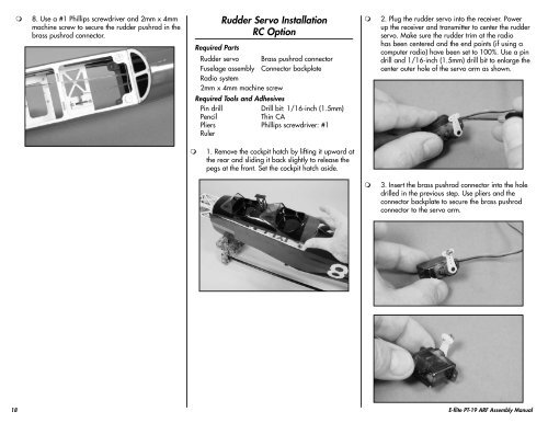
8. Use a #1 Phillips screwdriver and 2mm x 4mm<br />
machine screw to secure the rudder pushrod in the<br />
brass pushrod connector.<br />
Required Parts<br />
Rudder Servo Installation<br />
RC Option<br />
Rudder servo Brass pushrod connector<br />
Fuselage assembly Connector backplate<br />
Radio system<br />
2mm x 4mm machine screw<br />
Required Tools and Adhesives<br />
Pin drill<br />
Drill bit: 1/16-inch (1.5mm)<br />
Pencil<br />
Thin CA<br />
Pliers Phillips screwdriver: #1<br />
Ruler<br />
<br />
2. Plug the rudder servo into the receiver. Power<br />
up the receiver and transmitter to center the rudder<br />
servo. Make sure the rudder trim at the radio<br />
has been centered and the end points (if using a<br />
computer radio) have been set to 100%. Use a pin<br />
drill and 1/16-inch (1.5mm) drill bit to enlarge the<br />
center outer hole of the servo arm as shown.<br />
<br />
1. Remove the cockpit hatch by lifting it upward at<br />
the rear and sliding it back slightly to release the<br />
pegs at the front. Set the cockpit hatch aside.<br />
<br />
3. Insert the brass pushrod connector into the hole<br />
drilled in the previous step. Use pliers and the<br />
connector backplate to secure the brass pushrod<br />
connector to the servo arm.<br />
18 E-<strong>flite</strong> <strong>PT</strong>-<strong>19</strong> <strong>ARF</strong> <strong>Assembly</strong> <strong>Manual</strong>