

Navigation Functionalities for an Autonomous UAV Helicopter
Navigation Functionalities for an Autonomous UAV Helicopter
Navigation Functionalities for an Autonomous UAV Helicopter

Create successful ePaper yourself
Turn your PDF publications into a flip-book with our unique Google optimized e-Paper software.
10 CHAPTER 2. OVERVIEW<br />
The RMAX helicopter has a built-in attitude sensor called YAS (Yamaha<br />
Attitude Sensor) composed of three accelerometers <strong>an</strong>d three rate gyros.<br />
The output of the YAS are acceleration <strong>an</strong>d <strong>an</strong>gular rate on the three helicopter<br />
body axes (see section 3.3 <strong>for</strong> a definition of body axis). The YAS<br />
also computes the helicopter attitude <strong>an</strong>gles. Acceleration <strong>an</strong>d <strong>an</strong>gular<br />
rate from the YAS will be used as inertial measurement data <strong>for</strong> the sensor<br />
fusion process which will be described in chapter 5.<br />
The RMAX also has a built-in digital attitude control system called<br />
YACS (Yamaha Attitude Control System). The YACS stabilizes the helicopter<br />
attitude dynamics <strong>an</strong>d the vertical ch<strong>an</strong>nel dynamics. The YACS is<br />
used in all the helicopter control modes as <strong>an</strong> attitude stabilization system.<br />
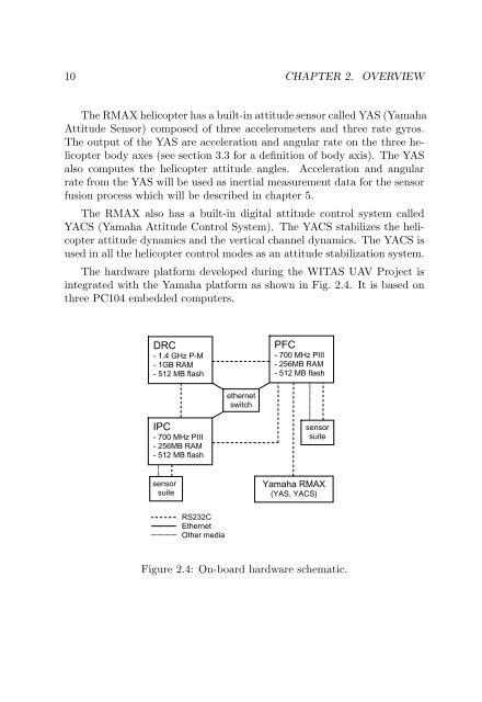
The hardware plat<strong>for</strong>m developed during the WITAS <strong>UAV</strong> Project is<br />
integrated with the Yamaha plat<strong>for</strong>m as shown in Fig. 2.4. It is based on<br />
three PC104 embedded computers.<br />
DRC<br />
- 1.4 GHz P-M<br />
- 1GB RAM<br />
- 512 MB flash<br />
IPC<br />
- 700 MHz PIII<br />
- 256MB RAM<br />
- 512 MB flash<br />
sensor<br />
suite<br />
RS232C<br />
Ethernet<br />
Other media<br />
ethernet<br />
switch<br />
PFC<br />
- 700 MHz PIII<br />
- 256MB RAM<br />
- 512 MB flash<br />
sensor<br />
suite<br />
Yamaha RMAX<br />
(YAS, YACS)<br />
Figure 2.4: On-board hardware schematic.


