Navigation Functionalities for an Autonomous UAV Helicopter
Navigation Functionalities for an Autonomous UAV Helicopter
Navigation Functionalities for an Autonomous UAV Helicopter
Create successful ePaper yourself
Turn your PDF publications into a flip-book with our unique Google optimized e-Paper software.
50 CHAPTER 4. PATH FOLLOWING CONTROL MODE<br />
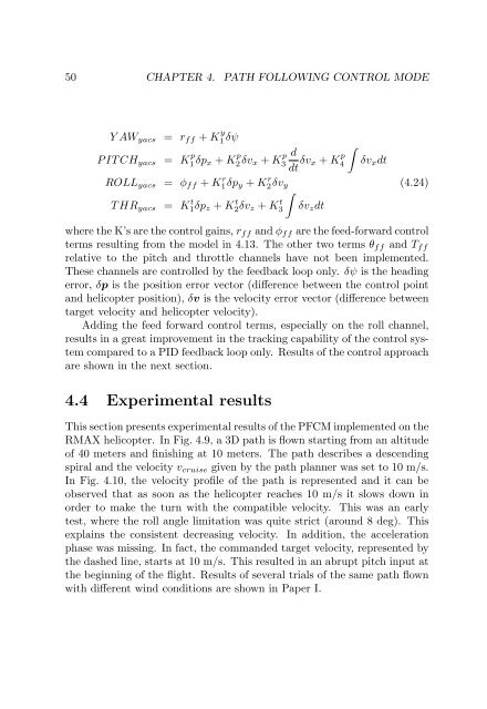
Y AWyacs = rff + K y<br />
1 δψ<br />
P IT CHyacs = K p<br />
1 δpx + K p<br />
2 δvx + K p<br />
3<br />
d<br />
dt δvx + K p<br />
�<br />
4<br />
δvxdt<br />
ROLLyacs = φff + K r 1δpy + K r 2δvy (4.24)<br />
T HRyacs = K t 1δpz + K t 2δvz + K t �<br />
3 δvzdt<br />
where the K’s are the control gains, rff <strong>an</strong>d φff are the feed-<strong>for</strong>ward control<br />
terms resulting from the model in 4.13. The other two terms θff <strong>an</strong>d Tff<br />
relative to the pitch <strong>an</strong>d throttle ch<strong>an</strong>nels have not been implemented.<br />
These ch<strong>an</strong>nels are controlled by the feedback loop only. δψ is the heading<br />
error, δp is the position error vector (difference between the control point<br />
<strong>an</strong>d helicopter position), δv is the velocity error vector (difference between<br />
target velocity <strong>an</strong>d helicopter velocity).<br />
Adding the feed <strong>for</strong>ward control terms, especially on the roll ch<strong>an</strong>nel,<br />
results in a great improvement in the tracking capability of the control system<br />
compared to a PID feedback loop only. Results of the control approach<br />
are shown in the next section.<br />
4.4 Experimental results<br />
This section presents experimental results of the PFCM implemented on the<br />
RMAX helicopter. In Fig. 4.9, a 3D path is flown starting from <strong>an</strong> altitude<br />
of 40 meters <strong>an</strong>d finishing at 10 meters. The path describes a descending<br />
spiral <strong>an</strong>d the velocity vcruise given by the path pl<strong>an</strong>ner was set to 10 m/s.<br />
In Fig. 4.10, the velocity profile of the path is represented <strong>an</strong>d it c<strong>an</strong> be<br />
observed that as soon as the helicopter reaches 10 m/s it slows down in<br />
order to make the turn with the compatible velocity. This was <strong>an</strong> early<br />
test, where the roll <strong>an</strong>gle limitation was quite strict (around 8 deg). This<br />
explains the consistent decreasing velocity. In addition, the acceleration<br />
phase was missing. In fact, the comm<strong>an</strong>ded target velocity, represented by<br />
the dashed line, starts at 10 m/s. This resulted in <strong>an</strong> abrupt pitch input at<br />
the beginning of the flight. Results of several trials of the same path flown<br />
with different wind conditions are shown in Paper I.


