Military Embedded Systems - Fall 2005 - Volume 1 Number 2
Military Embedded Systems - Fall 2005 - Volume 1 Number 2
Military Embedded Systems - Fall 2005 - Volume 1 Number 2

You also want an ePaper? Increase the reach of your titles
YUMPU automatically turns print PDFs into web optimized ePapers that Google loves.
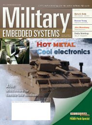
Performance enchancements<br />
Application<br />
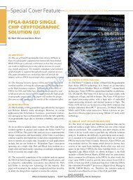
Mult i-Port ed Cont roller<br />
Memory<br />
<strong>Embedded</strong><br />
Processors<br />
Input<br />
Interface<br />
Interface<br />
Output<br />
DMA<br />
UPL<br />
Figure 1<br />
which column processor will work on each piece. It must then<br />
transmit each of these pieces to all of the column processors. The<br />
column processors receiving a piece of a row thus get just one<br />
element of each column. They must wait to accumulate enough<br />
rows before they can begin column processing.<br />
This puts a large memory requirement on each column processor<br />
to buffer so many rows. Because each column processor must<br />
transpose the matrix it receives, many CPU cycles are also spent<br />
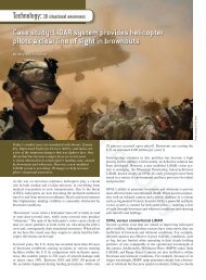
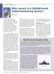
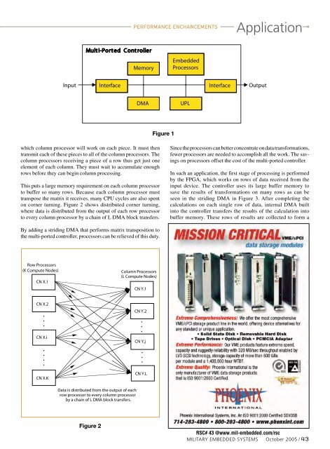
on corner turning. Figure 2 shows distributed corner turning,<br />
where data is distributed from the output of each row processor<br />
to every column processor by a chain of L DMA block transfers.<br />
Since the processors can better concentrate on data transformations,<br />
fewer processors are needed to accomplish all the work. The savings<br />
on processors offset the cost of the multi-ported controller.<br />
In such an application, the first stage of processing is performed<br />
by the FPGA, which works on rows of data received from the<br />
input device. The controller uses its large buffer memory to<br />
save the results of transformations on many rows as can be<br />
seen in the striding DMA in Figure 3. After completing the<br />
calculations on each single row of data, internal DMA built<br />
into the controller transfers the results of the calculation into<br />
buffer memory. These rows of results are collected to form a<br />
By adding a striding DMA that performs matrix transposition to<br />
the multi-ported controller, processors can be relieved of this duty.<br />
Row Processors<br />
(K Compute Nodes)<br />
CN X.1<br />
Column Processors<br />
(L Compute Nodes)<br />
CN Y.1<br />
CN X.2<br />
•<br />
•<br />
•<br />
CN X.i<br />
•<br />
•<br />
•<br />
•<br />
CN X.K<br />
CN Y.2<br />
•<br />
•<br />
•<br />
CN Y.j<br />
•<br />
•<br />
•<br />
CN Y.L<br />
Data is distributed from the output of each<br />
row processor to every column processor<br />
by a chain of L DMA block transfers.<br />
Figure 2<br />
RSC# 43 @www.mil-embedded.com/rsc<br />
<strong>Military</strong> EMBEDDED SYSTEMS October <strong>2005</strong> / 43