Military Embedded Systems - Fall 2005 - Volume 1 Number 2
Military Embedded Systems - Fall 2005 - Volume 1 Number 2
Military Embedded Systems - Fall 2005 - Volume 1 Number 2

Create successful ePaper yourself
Turn your PDF publications into a flip-book with our unique Google optimized e-Paper software.
Application<br />
Performance enchancements<br />
Multi-Ported Controller<br />
FPGA Processing<br />
Single Row of Data<br />
Regular DMA<br />
Buffer Memory<br />
DSP Processor<br />
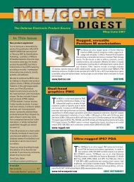
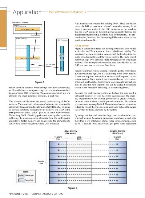
Any interlink can support this striding DMA. Since the data is<br />
sent to the DSP processors in order of consecutive memory locations,<br />
it does not matter to the DSP processor or the interlink<br />
that the DMA engine in the multi-ported controller fetched the<br />
data from nonconsecutive locations in its own memory. This process<br />
implies, however, that the striding DMA must reside on the<br />
multi-ported controller.<br />
.................................................................<br />
.................................................................<br />
.................................................................<br />
.................................................................<br />
.................................................................<br />
Copy of Single Row of Data<br />
.................................................................<br />
.................................................................<br />
.................................................................<br />
.................................................................<br />
.................................................................<br />
Figure 3<br />
Striding DMA<br />
Single<br />
Column<br />
of<br />
Data<br />
matrix in buffer memory. When enough rows have accumulated<br />
to allow efficient column processing, each column is transmitted<br />
to one of many DSP processors. The column consists of just one<br />
element, or a small number of elements, in each row.<br />
The elements of the rows are stored consecutively in buffer<br />
memory. The consecutive elements of columns are separated in<br />
memory by the corresponding elements of all of the other columns,<br />
so they are not stored consecutively in memory. The DMA to the<br />
DSP processors must “stride” past all of these other columns.<br />
The striding DMA effectively performs a scatter-gather operation,<br />
collecting the nonconsecutive elements from the multi-ported<br />
controller’s buffer memory and transferring the elements into<br />
consecutive memory locations on the DSP processor.<br />
All in stride<br />
Figure 4 further illustrates this striding operation. The strides<br />
are local to the DMA master, so this is called local striding. The<br />
transferred segment size is the same on both the local system, the<br />
multi-ported controller, and the remote system. The multi-ported<br />
controller skips over the local stride during its access to its local<br />
memory. The multi-ported controller may transmit data to the<br />
DSP processors or receive data from them.<br />
Figure 5 illustrates remote striding. The multi-ported controller is<br />
now shown on the right, but it is still acting as the DMA master.<br />
It must use separate transactions to access each segment on the<br />
remote system. Once again, it can transmit data or receive data.<br />
While not as efficient as local striding since separate transactions<br />
must be used for each segment, this can be useful if the remote<br />
system is not capable of mastering its own striding DMA.<br />
Because the multi-ported controller buffers the data until a<br />
sufficient number of rows has been accumulated, the memory<br />
requirement of the column processors is greatly reduced.<br />
In some cases without a multi-ported controller, the column<br />
processors are memory-limited. Compromises have to be made to<br />
reduce the size of the rows or columns in order to keep the matrix<br />
size within the limits imposed by the system.<br />
By using a multi-ported controller, larger rows or columns become<br />
practical because the column processors never have to deal with<br />
more than a few columns at a time. Since some operations, such<br />
as FFTs, require fewer instructions per pixel when performed<br />
Figure 4<br />
44 / October <strong>2005</strong> <strong>Military</strong> EMBEDDED SYSTEMS