DOWNLOAD 12-49 Paging Store and Forward Unit ... - Salcom
DOWNLOAD 12-49 Paging Store and Forward Unit ... - Salcom
DOWNLOAD 12-49 Paging Store and Forward Unit ... - Salcom

You also want an ePaper? Increase the reach of your titles
YUMPU automatically turns print PDFs into web optimized ePapers that Google loves.
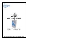
SALCOM <strong>12</strong>-84-0000 POCSAG RECEIVER with RELAY OUTPUTS Issue <strong>12</strong>84UF 1008<br />
<strong>12</strong>-84-0150 VHF/<strong>12</strong>-84-0450 UHF<br />
POCSAG 2 Relay Output Receiver<br />
1.0 GENERAL<br />
The <strong>12</strong>-84 POCSAG 2 Relay Output Receiver is available in two versions, a VHF <strong>12</strong>-<br />
84-0150 <strong>and</strong> a UHF <strong>12</strong>-84-0450 which provide two relay outputs which can be<br />
controlled remotely via SALCOM paging systems or wide area paging networks.<br />
2.0 OPERATION<br />
The unit receives <strong>and</strong> decodes a numeric or alphanumeric pager call. If the received<br />
unit number matches the <strong>12</strong>-84 unit number or group number, the relay outputs are<br />
switched according to the ON/OFF fields of the message.<br />
3.0 INSTALLATION<br />
Situate the <strong>12</strong>-84 away from direct sunlight, vibration <strong>and</strong> strong heat sources <strong>and</strong><br />
avoid close proximity to radio transmission equipment. The unit is not certified as<br />
intrinsically safe.<br />
In good coverage areas fit the aerial to the aerial socket as shown on the cover. An<br />
external aerial may be needed where reception is poor.<br />
Connect a <strong>12</strong> volt DC power supply to the power terminals (see figure 1). The <strong>12</strong>-84 is<br />
protected against reversed supply connection. The power source must be reasonably<br />
noise free.<br />
The connections to the relay contacts are made using the pairs of terminals, labelled<br />
‘relay 1' <strong>and</strong> ‘relay 2'. These are normally open contacts, but can be configured to be<br />
normally closed by special order. Relays are not to be connected directly to mains<br />
voltages.<br />
4.0 CORRECT OPERATION<br />
The operation of the unit is shown by the RED System LED. Correct operation is<br />
shown by this LED flashing. If the LED does not light, check the voltage on the supply<br />
terminal block.<br />
During the reception of a valid comm<strong>and</strong> with the correct RIC code, this LED will stay<br />
on for approximately one second. When a relay is comm<strong>and</strong>ed on, the corresponding<br />
LED will light next to the active relay.<br />
Sea Air <strong>and</strong> L<strong>and</strong> Communications Ltd Page 1