DOWNLOAD 12-49 Paging Store and Forward Unit ... - Salcom
DOWNLOAD 12-49 Paging Store and Forward Unit ... - Salcom
DOWNLOAD 12-49 Paging Store and Forward Unit ... - Salcom

Create successful ePaper yourself
Turn your PDF publications into a flip-book with our unique Google optimized e-Paper software.
<strong>12</strong>-<strong>49</strong> POCSAG PAGING STORE & FORWARD UNIT Issue <strong>12</strong><strong>49</strong>UEA4 1108<br />
<strong>12</strong>-<strong>49</strong>-0000 POCSAG PAGING<br />
STORE & FORWARD UNIT<br />
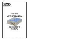
1.0 DESCRIPTION<br />
The SALCOM <strong>12</strong>-<strong>49</strong> <strong>Store</strong> <strong>and</strong> forward product is designed to receive <strong>and</strong> repeat<br />
POCSAG paging transmissions to increase the range of a paging network. It may be<br />
deployed as a VHF or a UHF unit by selection of the appropriate RF modules.<br />
The <strong>12</strong>-<strong>49</strong> is a composite system comprising of two, or optionally three separate<br />
SALCOM products:-<br />
1.1 The <strong>12</strong>-84 Receiver<br />
For VHF systems,the receiver used is the SALCOM <strong>12</strong>-84-0150 <strong>and</strong> for UHF<br />
the <strong>12</strong>-84-0450. Both of these receivers are identical in function <strong>and</strong> set-up<br />
(using the <strong>12</strong>-84 Programming Application), apart from the frequency b<strong>and</strong><br />
used.<br />
The receiver’s function is to intercept paging traffic off air from the host<br />
system. Valid paging traffic is compared to a database within the <strong>12</strong>-84 <strong>and</strong><br />
either accepted or ignored, depending upon the receiver settings. For further<br />
<strong>12</strong>-84 receiver information refer to the <strong>12</strong>-84 User Manual or help information<br />
in the <strong>12</strong>-84 programming application.<br />
Valid paging traffic is passed on to the <strong>12</strong>-62 transmitter where it is queued as<br />
separate messages for transmission when appropriate.<br />
As shipped, the default setup will accept <strong>and</strong> repeat all traffic.<br />
1.2 The <strong>12</strong>-62 Transmitter<br />
When operated on a single frequency, the <strong>12</strong>-<strong>49</strong> will only support a single<br />
message transmission sequence. That means as soon as the <strong>12</strong>-84 receiver<br />
outputs a single valid message, the <strong>12</strong>-62 transmitter begins transmitting the<br />
message.<br />
Any host system messages sent while the <strong>12</strong>-<strong>49</strong> is transmitting the message<br />
will not be received due to the antenna relay being in the transmit mode <strong>and</strong><br />
the <strong>12</strong>-84 being inactive.<br />
Sea Air & L<strong>and</strong> Communications Ltd - www.salcom.co.nz Page 2
<strong>12</strong>-<strong>49</strong> POCSAG PAGING STORE & FORWARD UNIT Issue <strong>12</strong><strong>49</strong>UEA4 1108<br />
To ensure that all valid messages are re-transmitted by the <strong>12</strong>-<strong>49</strong>, it is<br />
recommended that the originating transmitter adds a delay between each<br />
message. This delay should be at least 1 second longer than the<br />
transmission time of the current on-air message.<br />
The <strong>12</strong>-<strong>49</strong> supports a duplex mode allowing continuous message reception<br />
<strong>and</strong> transmission when the receive <strong>and</strong> transmit frequencies are different <strong>and</strong><br />
they each operate on separate antennas.<br />
Note: The <strong>12</strong>-62 also has 4 user inputs for the sending of pre-canned<br />
messages programmable from the <strong>12</strong>-62 PSD.<br />
In VHF systems the <strong>12</strong>-62-0150 transmitter is used <strong>and</strong> for UHF systems the<br />
<strong>12</strong>-62-0450 transmitter is used. These units provide up to 4 watts of RF <strong>and</strong><br />
are functionally identical, apart from the frequency b<strong>and</strong> used.<br />
The transmitter converts the POCSAG data into an FM modulated paging<br />
transmission.<br />
The transmission frequency is h<strong>and</strong>led by the <strong>12</strong>-62 PSD software. The RF<br />
output is made available to the aerial socket via a coaxial relay, allowing the<br />
one connection to be shared with the receiver.<br />
For further information on the <strong>12</strong>-62 Transmitter, refer to the User Manual or<br />
the <strong>12</strong>-62 programming application help.<br />
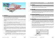
1.3 Power amplifier (optional)<br />
For systems where a higher power output is required, an 11-54 VHF, or 11-99<br />
UHF amplifier may be fitted. Either of these units will provide up to 25 Watts of<br />
RF power.<br />
2.0 PRODUCT SET-UP USING USING THE PSD SUPPORT PROGRAM<br />
The SALCOM <strong>12</strong>-<strong>49</strong> <strong>Store</strong> <strong>and</strong> <strong>Forward</strong> product is usually supplied on the correct<br />
frequency <strong>and</strong> in running order. Some settings however, such as the pager RIC<br />
database need to be edited by the user. This <strong>and</strong> all other settings are easily<br />
managed with the product support software.<br />
The product support software (<strong>12</strong>-84 or <strong>12</strong>-62 programming applications), are<br />
windows based programs which allow the user to set the system up as required.<br />
The program is started <strong>and</strong> a serial connection is made to each of the system<br />
components in turn, please refer to the documentation for each of these components<br />
<strong>and</strong> the on-line help provided within the programming applications.<br />
Sea Air & L<strong>and</strong> Communications Ltd - www.salcom.co.nz Page 3
<strong>12</strong>-<strong>49</strong> POCSAG PAGING STORE & FORWARD UNIT Issue <strong>12</strong><strong>49</strong>UEA4 1108<br />
2.1 <strong>12</strong>-<strong>49</strong> PSD System Requirements<br />
A pentium class or better computer running Windows 98 SE, Windows NT 4+,<br />
or Windows XP. A serial comm port <strong>and</strong> st<strong>and</strong>ard serial cable. A cross-over<br />
serial cable (supplied with the unit).<br />
2.2 Programming Method<br />
(1) Remove power from the <strong>12</strong>-<strong>49</strong>.<br />
(2) Remove the Serial Link Adapter from the D9 port on the rear of the unit<br />
<strong>and</strong> disconnect the aerial cable.<br />
(3) (a) For <strong>12</strong>-62 Transmitter Programming use a st<strong>and</strong>ard serial cable,<br />
directly connect the computer to the port <strong>12</strong>-<strong>49</strong> DB9 connector.<br />
(b) Re-apply power to the unit.<br />
(c) Run the <strong>12</strong>-62 PSD software on a compatible computer system<br />
(see System Requirements above).<br />
(d) Read the current settings from the unit.<br />
(e) Make any desired changes.<br />
(f) Re-program the unit with the new settings<br />
(g) Re-fit the Serial Link Adapter.<br />
(h) Toggle the power on the unit to reload the new settings.<br />
(4) For <strong>12</strong>-84 Receiver programming use the programming adapter cable<br />
supplied between the computer serial cable <strong>and</strong> the <strong>12</strong>-<strong>49</strong> DB9<br />
connector<br />
(a) Re-apply power to the unit.<br />
(b) Run the <strong>12</strong>-84 PSD software on a compatible computer system<br />
(see System Requirements above).<br />
(c) Read the current settings from the unit.<br />
(d) Make any desired changes.<br />
Sea Air & L<strong>and</strong> Communications Ltd - www.salcom.co.nz Page 4
<strong>12</strong>-<strong>49</strong> POCSAG PAGING STORE & FORWARD UNIT Issue <strong>12</strong><strong>49</strong>UEA4 1108<br />
(e)<br />
(f)<br />
(g)<br />
Re-program the unit with the new settings.<br />
Re-fit the Serial Link Adapter.<br />
Toggle the power on the unit to reload the new settings.<br />
2.3 <strong>12</strong>-62 Programming<br />
Changes to the <strong>12</strong>-62 are detailed in the <strong>12</strong>-62 User manual.<br />
Points to note are: The serial protocol in the General Tab MUST remain set<br />
to “<strong>12</strong>-84” otherwise the serial data from the <strong>12</strong>-84 will not be re-transmitted.<br />
2.4 <strong>12</strong>-84 Programming<br />
Changes to the <strong>12</strong>-84 are detailed in the <strong>12</strong>-84 User manual.<br />
Points to note: It is recommended to set the “Decode Any RIC” to NO <strong>and</strong> in<br />
the “Receive Codes” tab set a Low RIC <strong>and</strong> High RIC to avoid any false<br />
decodes from the <strong>12</strong>-84 receiver.<br />
As a minimum set the #1 Low RIC to 00000008 <strong>and</strong> the Hi RIC to 19999999<br />
Also note the “Type” field controls what type of POCSAG message is decoded for the<br />
associated Low to High RIC codes (Numeric or AlphaNumeric).<br />
Eg:<br />
Receive Codes Tab<br />
#1, Low RIC 0900000, High RIC 0999999, Type N<br />
Means that all RICs between 0900000 <strong>and</strong> 0999999 will be decoded as<br />
Numeric<br />
#2, Low RIC 1000000, High RIC 1999999, Type A<br />
Means that all RICs between 1000000 <strong>and</strong> 1999999 will be decoded as<br />
AlphaNumeric<br />
NB: In the above example any RIC’s below 0900000 <strong>and</strong> above 1999999 will<br />
NOT be decoded at all.<br />
Sea Air & L<strong>and</strong> Communications Ltd - www.salcom.co.nz Page 5
<strong>12</strong>-<strong>49</strong> POCSAG PAGING STORE & FORWARD UNIT Issue <strong>12</strong><strong>49</strong>UEA4 1108<br />
Sea Air & L<strong>and</strong> Communications Ltd - www.salcom.co.nz Page 6
<strong>12</strong>-<strong>49</strong> POCSAG PAGING STORE & FORWARD UNIT Issue <strong>12</strong><strong>49</strong>UEA4 1108<br />
3.0 WARRANTY<br />
Our Products are warranted for a period of <strong>12</strong> months from date of purchase against<br />
faulty materials <strong>and</strong> workmanship. Should any fault occur the unit should be<br />
returned to the vendor, freight pre-paid. Please include a description of the fault to<br />
assist with prompt return. Any unauthorized alterations or repairs will invalidate the<br />
warranty.<br />
4.0 DISCLAIMER<br />
All information provided in this document is carefully prepared <strong>and</strong> offered in good<br />
faith as a guide in the installation, use <strong>and</strong> servicing of our products. Installers must<br />
ensure that the final installation operates satisfactorily within the relevant regulatory<br />
requirements. We accept no responsibility for incorrect installation. We reserve the<br />
right to change products, specifications, <strong>and</strong> installation data at any time, without<br />
notice.<br />
SEA AIR & LAND COMMUNICATIONS LTD<br />
PO Box 22-621, <strong>12</strong>0 St.Asaph Street, Christchurch, New Zeal<strong>and</strong><br />
Phone: (03) 379-2298 Fax: (03) 365-1580 Email: info@salcom.co.nz<br />
Visit us at www.salcom.co.nz<br />
Sea Air & L<strong>and</strong> Communications Ltd - www.salcom.co.nz Page 7
SALCOM <strong>12</strong>-84-0000 POCSAG RECEIVER with RELAY OUTPUTS Issue <strong>12</strong>84UF 1008<br />
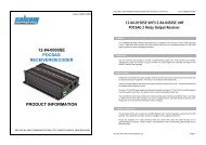
<strong>12</strong>-84-0150 VHF/<strong>12</strong>-84-0450 UHF<br />
POCSAG 2 Relay Output Receiver<br />
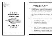
1.0 GENERAL<br />
The <strong>12</strong>-84 POCSAG 2 Relay Output Receiver is available in two versions, a VHF <strong>12</strong>-<br />
84-0150 <strong>and</strong> a UHF <strong>12</strong>-84-0450 which provide two relay outputs which can be<br />
controlled remotely via SALCOM paging systems or wide area paging networks.<br />
2.0 OPERATION<br />
The unit receives <strong>and</strong> decodes a numeric or alphanumeric pager call. If the received<br />
unit number matches the <strong>12</strong>-84 unit number or group number, the relay outputs are<br />
switched according to the ON/OFF fields of the message.<br />
3.0 INSTALLATION<br />
Situate the <strong>12</strong>-84 away from direct sunlight, vibration <strong>and</strong> strong heat sources <strong>and</strong><br />
avoid close proximity to radio transmission equipment. The unit is not certified as<br />
intrinsically safe.<br />
In good coverage areas fit the aerial to the aerial socket as shown on the cover. An<br />
external aerial may be needed where reception is poor.<br />
Connect a <strong>12</strong> volt DC power supply to the power terminals (see figure 1). The <strong>12</strong>-84 is<br />
protected against reversed supply connection. The power source must be reasonably<br />
noise free.<br />
The connections to the relay contacts are made using the pairs of terminals, labelled<br />
‘relay 1' <strong>and</strong> ‘relay 2'. These are normally open contacts, but can be configured to be<br />
normally closed by special order. Relays are not to be connected directly to mains<br />
voltages.<br />
4.0 CORRECT OPERATION<br />
The operation of the unit is shown by the RED System LED. Correct operation is<br />
shown by this LED flashing. If the LED does not light, check the voltage on the supply<br />
terminal block.<br />
During the reception of a valid comm<strong>and</strong> with the correct RIC code, this LED will stay<br />
on for approximately one second. When a relay is comm<strong>and</strong>ed on, the corresponding<br />
LED will light next to the active relay.<br />
Sea Air <strong>and</strong> L<strong>and</strong> Communications Ltd Page 1
SALCOM <strong>12</strong>-84-0000 POCSAG RECEIVER with RELAY OUTPUTS Issue <strong>12</strong>84UF 1008<br />
5.0 UNIT NUMBER<br />
Each unit will respond only to messages containing a matching <strong>Unit</strong> Number. Up to 99<br />
unique unit numbers are available. Any number of units can be programmed with the<br />
same unit number.<br />
The <strong>Unit</strong> Number comprising of 2 digits is selected using the configuration software.<br />
6.0 MONOSHOT<br />
Output mono-shot (momentary) operation can be enabled by using the configuration<br />
software. The Relay output can have its own Mono-shot time, ranging from 25mS to 30<br />
minutes in 25mS steps.<br />
Setting the value to 0 disables the mono-shot timer altogether, <strong>and</strong> the relay output is<br />
latched until comm<strong>and</strong>ed off.<br />
7.0 RADIO CHANNEL FREQUENCY<br />
The frequency of the radio channel is preset at the SALCOM factory. The nominal<br />
tuning range is: VHF 148 to 161 MHz <strong>and</strong> UHF 450 to 470 MHz.<br />
8.0 SPECIFICATION<br />
Frequency B<strong>and</strong>s<br />
VHF: 148-161MHz<br />
UHF: 450-470MHz<br />
Enclosure.<br />
135mm x 100mm x 30mm. extruded aluminium case.<br />
Supply Voltage 10v to 17v, Nominal <strong>12</strong>V.<br />
Current drain<br />
St<strong>and</strong>by 60mA plus 18mA per energised relay.<br />
Relay contacts<br />
Temperature limits<br />
Environmental protection<br />
Frequency selection<br />
method<br />
RX sensitivity<br />
Aerial connection<br />
<strong>Paging</strong> protocol<br />
1Amp @24VDC (Not suitable for 240VAC<br />
connection)<br />
-10 to +50degC<br />
Needs protection from weather<br />
Synthesized, programmable via <strong>Salcom</strong> <strong>12</strong>-84SE<br />
PSD<br />
Approx -<strong>12</strong>4dBm<br />
BNC connector. Supplied with aerial<br />
POCSAG 5<strong>12</strong> or <strong>12</strong>00baud.<br />
Sea Air <strong>and</strong> L<strong>and</strong> Communications Ltd Page 2
SALCOM <strong>12</strong>-84-0000 POCSAG RECEIVER with RELAY OUTPUTS Issue <strong>12</strong>84UF 1008<br />
9.0 COMMANDS<br />
The OUTPUT Relay of the <strong>12</strong>-84 controlled by a series of numeric comm<strong>and</strong>s sent in<br />
the form of a numeric or alphanumeric pager message. Note: For best sensitivity <strong>and</strong><br />
range, it is better to send the comm<strong>and</strong> as a numeric paging message, as this uses<br />
the least number of characters.<br />
Comm<strong>and</strong> Format: UUx..x0y..y9<br />
UU <strong>Unit</strong> number<br />
This must be entered as 2 digits 00 - 99.<br />
x Relay to go ON.<br />
The st<strong>and</strong>ard relay in the <strong>12</strong>-84 is designated as channel 1. Therefore the<br />
comm<strong>and</strong> should carry “1" in this position. If a second relay is fitted to the<br />
unit, this digit can be 1 or 2 or both. Any combination of Digits 1or 2 can be<br />
entered in any order. If none are entered then the function has no effect.<br />
0 End entry of Output ON values<br />
This terminates the list of outputs to turn on. This character in m<strong>and</strong>atory.<br />
y Relay to go OFF.<br />
As per “Relay to go ON” above, but this designates the relay to go OFF<br />
instead.<br />
9 End entry of Outputs OFF values & Ignore rest of entry.<br />
This terminates the list of outputs to turn OFF <strong>and</strong> Informs the <strong>12</strong>-84-0000 to<br />
ignore the rest of the message. This allows a text message to follow the<br />
comm<strong>and</strong>.<br />
E.g. Controlling relays using the TELECOM <strong>Paging</strong> Network<br />
Message: 026PPPPPPPP UUx..x0x..x9<br />
| | |<br />
| | |<strong>12</strong>-84-0000 Comm<strong>and</strong><br />
| | the pager number[TELECOM PAGER No]<br />
| the network access number<br />
E.g. Controlling relays using a SALCOM POCSAG TRANSMITTER<br />
Message: NN[MESSAGE]UUx..x0x..x9<br />
| | |<br />
| | | <strong>12</strong>-84-0000 Comm<strong>and</strong><br />
| | the message button<br />
| The quick dial number<br />
10.0 <strong>12</strong>-84 SETUP<br />
The programmable parameters of the <strong>12</strong>-84 can be configured using the SALCOM<br />
<strong>12</strong>-46 programming cable (ordered separately) <strong>and</strong> the <strong>12</strong>-84SE PSD software which<br />
can be downloaded from the support area of the <strong>Salcom</strong> web page<br />
www.salcom.co.nz.<br />
Sea Air <strong>and</strong> L<strong>and</strong> Communications Ltd Page 3
SALCOM <strong>12</strong>-84-0000 POCSAG RECEIVER with RELAY OUTPUTS Issue <strong>12</strong>84UF 1008<br />
(1) Connect the <strong>12</strong>-46 programming cable to the programming connector on the<br />
<strong>12</strong>-84 (refer to figures 2 <strong>and</strong> 3) <strong>and</strong> to any PC com port.<br />
(2) Apply power to the <strong>12</strong>-84.<br />
(3) Press the Connect button. If connecting is not successful, ensure that com<br />
port settings are correct.<br />
(4) Once connected, click on the Read button <strong>and</strong> the current setup of the target<br />
unit will be read <strong>and</strong> displayed.<br />
(5) Make any desired changes by entering data or modifying data in the<br />
appropriate fields.<br />
(6) Reprogram the unit by clicking the Program button to upload the changes to<br />
the <strong>12</strong>-84.<br />
11.0 CORRECT OPERATION<br />
Some options are available for the <strong>12</strong>-84 to extend its use to other situations. These<br />
options can only be fitted by the SALCOM factory <strong>and</strong> must be requested at the initial<br />
order.<br />
Sea Air <strong>and</strong> L<strong>and</strong> Communications Ltd Page 4
SALCOM <strong>12</strong>-84-0000 POCSAG RECEIVER with RELAY OUTPUTS Issue <strong>12</strong>84UF 1008<br />
(1) An external aerial can be fitted by unplugging the existing aerial <strong>and</strong> plugging<br />
in the BNC aerial connector on the coaxial aerial lead.<br />
(2) Fitted relays can be installed as normally closed.<br />
<strong>12</strong>.0 CONNECTIONS<br />
Pin numbering: looking into the sockets with the<br />
power connector on the left, pin 1 is on the left.<br />
S2 RJ<strong>12</strong> - 6 WAY<br />
PROGRAMMING PORT<br />
S10 RJ45 - 8 WAY RELAY<br />
CONNECTION PORT<br />
Pin Description Pin Description<br />
1 Ground 1 Unused<br />
2 System LED 2 Unused<br />
3 Unused 3 Relay 2 Normally Open<br />
4 Power LED 4 Relay 2 Normally Closed<br />
5 RS232 out 5 Relay 2 Common<br />
6 RS232 in 6 Relay 1 Normally Open<br />
7 Relay 1 Normally Closed<br />
8 Relay 1 Common<br />
Sea Air <strong>and</strong> L<strong>and</strong> Communications Ltd Page 5
SALCOM <strong>12</strong>-84-0000 POCSAG RECEIVER with RELAY OUTPUTS Issue <strong>12</strong>84UF 1008<br />
13.0 WARRANTY<br />
Our Products are warranted for a period of <strong>12</strong> months from date of purchase against<br />
faulty materials <strong>and</strong> workmanship.<br />
Should any fault occur the unit should be returned to the vendor, freight pre-paid.<br />
Please include a description of the fault to assist with prompt return. Any unauthorized<br />
alterations or repairs will invalidate the warranty.<br />
14.0 DISCLAIMER<br />
All information provided in this document is carefully prepared <strong>and</strong> offered in good<br />
faith as a guide in the installation, use <strong>and</strong> servicing of our products. Installers must<br />
ensure that the final installation operates satisfactorily within the relevant regulatory<br />
requirements. We accept no responsibility for incorrect installation.<br />
We reserve the right to change products, specifications, <strong>and</strong> installation data at any<br />
time, without notice.<br />
SEA AIR & LAND COMMUNICATIONS LTD<br />
PO Box 22-621, <strong>12</strong>0 St.Asaph Street, Christchurch, New Zeal<strong>and</strong><br />
Phone: (03) 379-2298 Fax: (03) 365-1580 Email: info@salcom.co.nz<br />
Visit us at www.salcom.co.nz<br />
Sea Air <strong>and</strong> L<strong>and</strong> Communications Ltd Page 6
<strong>12</strong>-62 SYNTHESIZED NRZ TRANSMITTER USER’S MANUAL Issue <strong>12</strong>62UE 1008<br />
<strong>12</strong>-62 POCSAG<br />
PAGING TRANSMITTER<br />
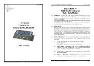
1.0 DESCRIPTION<br />
The <strong>12</strong>-62 is a 138 - 174 MHz (VHF) or 427.5 - 475 MHz (UHF) 4 watt POCSAG<br />
paging transmitter with an in-built encoder. All parameters are programmable such as:<br />
frequency, power output, deviation, POCSAG or NRZ data transmission.<br />
The unit can be controlled via a USB port or an RS232 serial interface to provide<br />
numeric, alphanumeric <strong>and</strong> tone-only POCSAG encoding. This enables a user to call<br />
a pager (over 2,000,000 codes), append an appropriate priority level (1 of 4), <strong>and</strong> add<br />
a numeric or alphanumeric message.<br />
The <strong>12</strong>-62 supports multiple message queuing, <strong>and</strong> will queue up to eight 240<br />
character messages, or as many smaller messages that will fit into the available<br />
memory buffer (up to 80). Pre-defined input messages are limited to a maximum<br />
length of 40 characters which may be configured using the <strong>Salcom</strong> programming<br />
software. Control via the USB or Serial port is achieved using ASCII character<br />
comm<strong>and</strong>s.<br />
The unit supports 4 discrete inputs with a different pre-programmed message on high<br />
<strong>and</strong>/or low transition, plus voltage detection messages on the power input.<br />
The inputs can be configured for a number of options. Provision to transmit a<br />
message more than once <strong>and</strong> variable time between transmissions are catered for.<br />
The USB port or the RS232 serial port can be used to initiate paging transmissions<br />
using the SALCOM propriety protocol, <strong>Paging</strong> Entry Protocol (PET) or Telocator<br />
Alphanumeric Protocol (TAP) PG1 protocol. These ports can be used concurrently<br />
making it possible to connect a telephone interface unit <strong>and</strong> still initiate paging<br />
transmissions via the USB port.<br />
Over temperature cutout: If the transmitter operates for extended periods in a hot<br />
environment, a protective thermal cutout may operate to reduce the output power to a<br />
safe level. It will reset when the unit temperature has fallen to below 70 deg.<br />
Transmitter Duty cycle: The transmitter duty cycle is rated as 50% with a max ‘on’<br />
time of 5 minutes. Higher duty cycles may be possible. Contact <strong>Salcom</strong> for advice.<br />
2.0 WARRANTY<br />
Our Products are warranted for a period of <strong>12</strong> months from date of purchase against<br />
faulty materials <strong>and</strong> workmanship. Should any fault occur the unit should be returned<br />
to the vendor, freight pre-paid. Please include a description of the fault to assist with<br />
prompt return. Any unauthorized alterations or repairs will invalidate the warranty.<br />
Sea Air <strong>and</strong> L<strong>and</strong> Communications Ltd Page 1
<strong>12</strong>-62 SYNTHESIZED NRZ TRANSMITTER USER’S MANUAL Issue <strong>12</strong>62UE 1008<br />
3.0 DISCLAIMER<br />
All information provided in this document is carefully prepared <strong>and</strong> offered in good<br />
faith as a guide in the installation <strong>and</strong> use of the <strong>12</strong>-62. Installers must ensure that the<br />
final installation operates satisfactorily within the relevant regulatory requirements.<br />
We accept no responsibility for incorrect installation.<br />
We reserve the right to change products, specifications, <strong>and</strong> installation data at any<br />
time, without notice.<br />
4.0 MECHANICAL DESCRIPTION<br />
The <strong>12</strong>-62 is enclosed in an extruded aluminium box.<br />
The end-plates unscrew <strong>and</strong> the lid slides off to allow access to the component side of<br />
the pcb. The complete pcb can then be slid out of the case if required, the heatsink<br />
relies on a light pressure contact with the case for heat dissipation, The case has four<br />
holes for mounting the unit. The <strong>12</strong>-62 must be mounted away from sources of heat,<br />
damp or vibration.<br />
5.0 INSTALLATION<br />
The power supply is connected via P1, green power connector to +13.8 Volts <strong>and</strong><br />
Ground. The supply input is protected against reversed connection.<br />
Radiation Hazard: Important! To comply with FCC Controlled /Occupational<br />
Exposure Limits, the aerial must be positioned or mounted to operate at least 0.2<br />
metre away from Occupational Staff <strong>and</strong> 0.5 metre away from the General Public. Use<br />
only supplied aerial.<br />
It is recommended to site the aerial a few metres away from the <strong>12</strong>-62 to avoid the<br />
possibility of RF feedback causing problems with the transmitter operation.<br />
An outside aerial is preferable <strong>and</strong> will provide better radio coverage. The aerial<br />
connection is via the BNC connector, <strong>and</strong> should present a nominal load of 50 S, with<br />
a VSWR of better than 1.8:1.<br />
External indicators consist of a power indicator GREEN LED, normally flashing ON<br />
once per second to indicate healthy microcontroller operation.<br />
After a debounce period, the green LED will flash rapidly if the low supply detector is<br />
activated.<br />
The RED LED will indicate when the unit is transmitting.<br />
A flashing RED LED indicates the unit cannot transmit as either the synthesiser is out<br />
of lock, the <strong>12</strong>-62 is critically hot or an internal fault has been detected.<br />
Sea Air <strong>and</strong> L<strong>and</strong> Communications Ltd Page 2
<strong>12</strong>-62 SYNTHESIZED NRZ TRANSMITTER USER’S MANUAL Issue <strong>12</strong>62UE 1008<br />
S2 <strong>and</strong> S10 Connections<br />
S2 Connections:-<br />
S10 Connections:-<br />
Pin 1 Ground Pin 1 PTT OUT, 50mA max.<br />
Pin 2 Interrupt Pin 2 GROUND<br />
Pin 3 SCL Pin 3 Discrete Input 4<br />
Pin 4 SDA Pin 4 Discrete Input 3<br />
Pin 5 RS232 Tx Pin 5 Discrete Input 2<br />
Pin 6 RS232 Rx Pin 6 Discrete Input 1<br />
Pin 7 PTT Input for NRZ operation<br />
Pin 8 Modulation Input for NRZ operation<br />
6.0 OPERATION<br />
The <strong>12</strong>-62 can transmit 3 types of POCSAG message, with any one of 4 function<br />
levels:<br />
• Alphanumeric transmissions. Message can contain any alphanumeric ‘ASCII’<br />
character.<br />
• Numeric transmissions. Message contains only Numeric characters <strong>and</strong> some<br />
symbols.<br />
• Tone Only transmissions (Alphanumeric or numeric with no message)<br />
6.1 Alphanumeric transmissions<br />
Messages can contain any alphanumeric character. The <strong>12</strong>-62 will accept the<br />
st<strong>and</strong>ard ASCII 7 bit character set.<br />
6.2 Numeric transmissions<br />
Messages can contain numeric characters <strong>and</strong> some symbols.<br />
These can convey a telephone number, or other numerically coded information.<br />
The transmitted message is shorter, <strong>and</strong> therefore there is a smaller chance of<br />
errors received by the pager.<br />
The numeric character set is as follows:<br />
0 1 2 3 4 5 6 7 8 9 [ ] - U <br />
Sea Air <strong>and</strong> L<strong>and</strong> Communications Ltd Page 3
<strong>12</strong>-62 SYNTHESIZED NRZ TRANSMITTER USER’S MANUAL Issue <strong>12</strong>62UE 1008<br />
6.3 Tone Only transmissions<br />
Any numeric or alphanumeric paging message without an actual text message is<br />
also considered ‘Tone Only’.<br />
A function level will control the number of beeps on the receiver (four different<br />
function levels can be sent).<br />
7.0 INITIATING TRANSMISSION<br />
There are four ways of initiating a paging message transmission:<br />
(1) Using the external discrete inputs (action)<br />
(2) Supply detector threshold (action)<br />
(3) Watchdog (action)<br />
(4) RS232 Serial comm<strong>and</strong>s<br />
An action is defined as a paging message, RIC (Receiver Identification Code or<br />
capcode) <strong>and</strong> flags. Flags are discussed in the PSD (product support disk) section.<br />
7.1 External Discrete Inputs<br />
An action can be initiated from the 4 external inputs with an input transition to<br />
LOW (connection to GND) <strong>and</strong>/or HIGH (input floating or connection to >+3.5v).<br />
7.2 Low supply message<br />
After a debounce period, the low-supply detector can initiate an action for both<br />
“supply going high” <strong>and</strong> “supply going low”conditions.<br />
7.3 Watchdog<br />
The watchdog feature will initiate an action after a predetermined period. The<br />
watchdog also optionally allows the transmission of the current state of selected<br />
inputs (including supply level).<br />
7.4 Using the RS232 Serial Comm<strong>and</strong>s<br />
Serial comm<strong>and</strong>s can be “manually” issued to an <strong>12</strong>-62 using a terminal<br />
program such as PROCOMM or Hyper-terminal.<br />
Tone only, numeric <strong>and</strong> alphanumeric pagers can be called using serial<br />
comm<strong>and</strong>s. These comm<strong>and</strong>s will be processed in parallel with other inputs<br />
actions for transmission. Some basic comm<strong>and</strong>s are described in section 7.4.1.<br />
Information on the full protocol comm<strong>and</strong> set is available on request.<br />
8.0 PROTOCOL COMMAND SET<br />
CA<br />
Usage:<br />
Description:<br />
Example:<br />
Response:<br />
CA[][]<br />
Call alphanumeric pager<br />
CA1119358 1 Please return to reception<br />
CA11193581Page Sent<br />
Sea Air <strong>and</strong> L<strong>and</strong> Communications Ltd Page 4
<strong>12</strong>-62 SYNTHESIZED NRZ TRANSMITTER USER’S MANUAL Issue <strong>12</strong>62UE 1008<br />
CN<br />
Usage:<br />
Description:<br />
Example:<br />
Response:<br />
CN[][]<br />
Call numeric pager<br />
CN1119358 1 777<br />
CN11193581Page Sent<br />
RES<br />
Usage:<br />
Description:<br />
Example:<br />
Response:<br />
RES<br />
Reset <strong>12</strong>-62 microcontroller<br />
RES<br />
SALCOM <strong>12</strong>-62-0000 VX.XX<br />
SN?<br />
Usage:<br />
Description:<br />
Example:<br />
Response:<br />
SN?<br />
Retrieve unit serial number <strong>and</strong> firmware revision<br />
SN?<br />
SALCOM <strong>12</strong>-62-0000 VX.XX 5<strong>12</strong>2345<br />
8.1 Error Codes/Reports<br />
ER1 SYNTAX<br />
ER3 OPERND<br />
ER6 BUSY<br />
ER7 OVERTEMP<br />
You entered an invalid comm<strong>and</strong><br />
You entered a valid comm<strong>and</strong> with invalid values<br />
<strong>12</strong>-62 is too busy to process the entered comm<strong>and</strong>, try<br />
again later.<br />
<strong>12</strong>-62 is critically hot, transmission not possible until<br />
cooler.<br />
9.0 TROUBLESHOOTING<br />
The following table may help in problem solving where necessary.<br />
Fault<br />
No illumination of Green LED<br />
Input activated but no transmission<br />
<strong>Unit</strong> transmits but nothing received<br />
No RS232 serial communication<br />
Red LED flashes rapidly<br />
Green led flashes rapidly<br />
<strong>Unit</strong> starts, but does not complete<br />
transmission<br />
Check<br />
Bad power supply connection<br />
PSD configuration incorrect<br />
Poor aerial. Wrong frequency, RIC, baud-rate. Power<br />
too low. <strong>Unit</strong> too hot. Too much vibration<br />
Comport connections, baud-rate 9600 no parity, eight<br />
data bits, one stop bit<br />
VCO out of lock, unit too hot or internal fault detected.<br />
Connecting a serial lead to the <strong>12</strong>-62 will allow the<br />
nature of the fault condition to be determined.<br />
Low supply detector threshold<br />
Poor supply volts, RF interference.<br />
Sea Air <strong>and</strong> L<strong>and</strong> Communications Ltd Page 5
<strong>12</strong>-62 SYNTHESIZED NRZ TRANSMITTER USER’S MANUAL Issue <strong>12</strong>62UE 1008<br />
10.0 PROGRAMMING<br />
10.1 Installing the VCP USB Driver<br />
To use the USB port to communicate with the <strong>12</strong>-62, a Virtual Com Port driver<br />
must be installed on the PC.<br />
To install the Silicon Laboratories USB driver, run the driver installer<br />
CP210x_VCP_Win2K_XP_S2K3.exe provided on the supplied PSD CD <strong>and</strong><br />
follow the on screen instructions. Once the driver is installed, an additional<br />
COM port will be available via the <strong>Salcom</strong> PSD programming software.<br />
VCP USB driver updates are provided periodically by Silicon Laboratories <strong>and</strong><br />
may be downloaded free of charge from https://www.silabs.com/support.<br />
10.2 Preparations for Connecting the Programming Software<br />
To change the field programmable options, the unit must be connected to a PC<br />
running the <strong>12</strong>-62 PSD programming software in Windows XP via either the<br />
preferred USB port S8 (using the supplied USB mini cable), or the st<strong>and</strong>ard<br />
serial port S2.<br />
To use the USB connector, the supplied virtual COM port USB driver must be<br />
installed<br />
Note: To make up a serial cable, the S2 connections are shown on page 3.<br />
Alternatively purchase an optional <strong>Salcom</strong> serial programming cable.<br />
The <strong>12</strong>-62 must be powered during programming, +13.8V to power terminals.<br />
Ensure that the <strong>12</strong>-62 PSD has the correct com port selected. Once correctly<br />
configured perform the following:<br />
1 Press connect. The status at the bottom of the <strong>12</strong>-62 PSD will indicate if<br />
successfully connected.<br />
2 Press the read button, or load a PSD configuration file. This will load all<br />
settings of the <strong>12</strong>-62, which is required before any changes can be<br />
programmed. The <strong>12</strong>-62 PSD will provide feedback if the user selected<br />
operations are successful.<br />
10.3 Using the Programming Software<br />
The <strong>12</strong>-62 PSD allows the user to configure the following characteristics:<br />
> Input actions, watchdog, low supply detector <strong>and</strong> POCSAG transmission<br />
settings<br />
> Pre-defined messages<br />
> RF frequency, deviation <strong>and</strong> output power<br />
> 99 pager numbers for use with the <strong>Salcom</strong> 11-36 telephone interface.<br />
Once the program is running, the opening screen appears . Use the mouse to<br />
select the configuration fields for each feature.<br />
Sea Air <strong>and</strong> L<strong>and</strong> Communications Ltd Page 6
<strong>12</strong>-62 SYNTHESIZED NRZ TRANSMITTER USER’S MANUAL Issue <strong>12</strong>62UE 1008<br />
10.4 PSD Input Configuration<br />
All inputs may be configured in a similar fashion, including supply voltage<br />
monitoring. The input drop down box provides support for the 4 inputs available<br />
on S10.<br />
The battery input is at the very bottom of the input list. Each input may have a<br />
message defined for both a high <strong>and</strong> low state. Input parameters may be<br />
configured as follows:<br />
Pager type: Numeric or Alpha numeric. Tone only pagers are supported by<br />
ensuring that the message field is left blank.<br />
Beep Level: Page beep levels 1-4.<br />
RIC Code: Pager ID. Valid Codes are:<br />
0000008 to 2007663<br />
2007672 to 2045055<br />
2045064 to 2097143<br />
0000000 may be used as a “drop” code. This may be used for the watchdog<br />
when the watchdog is used, but a watchdog message is to be suppressed.<br />
Message: User message, up to 40 characters in length.<br />
Transmission Count: How many times that message will be sent if triggered.<br />
Enabled: When selected, the configured message will be sent when triggered.<br />
Resend with Watchdog: When the watchdog is enabled, the input message<br />
will be sent periodically as configured if in the enabled state.<br />
Sea Air <strong>and</strong> L<strong>and</strong> Communications Ltd Page 7
<strong>12</strong>-62 SYNTHESIZED NRZ TRANSMITTER USER’S MANUAL Issue <strong>12</strong>62UE 1008<br />
Initial Input State: Input messages are sent when transitioning to the enabled<br />
state. If on start-up “Current” has been selected the current input state is read,<br />
so that the input message will not be sent on start-up.<br />
If “High” is selected, the input on startup is assumed to be in the high state, so<br />
when found to be low (if this is the case) the transition will result in a message<br />
being sent (if enabled). If “Low”, the opposite will occur, the input is assumed to<br />
be low on startup, the transition to high resulting in message being transmitted<br />
(if enabled, <strong>and</strong> the input is in the high state).<br />
10.5 PSD General configuration<br />
Selecting Options->General will display the general configuration screen as<br />
shown overleaf. The following items may be set here.<br />
Baud Rate: Changing this setting will result in all configured messages to be<br />
sent at the selected baud rate (5<strong>12</strong> or <strong>12</strong>00 Baud).<br />
Protocol: Allows the serial protocol to be changed<br />
Input Debounce: The time delay between the input being triggered <strong>and</strong> the<br />
message being sent.<br />
Enable 11-36 Support: Enabling 11-36 support will allow the <strong>Salcom</strong> 11-36-<br />
0000 telephone interface to be configured. Configuration options will become<br />
available through the options tab (refer to 10.7: PSD 11-36 Support).<br />
Invert Tx data: Internally generated data is inverted when Internal modulation is<br />
selected. The Invert Tx Data option is unavailable when external modulation is<br />
selected.<br />
Resend Delay: When an input has been configured with a transmission count<br />
greater than 1, then the resend delay is the delay in seconds before sending the<br />
message again.<br />
Sea Air <strong>and</strong> L<strong>and</strong> Communications Ltd Page 8
<strong>12</strong>-62 SYNTHESIZED NRZ TRANSMITTER USER’S MANUAL Issue <strong>12</strong>62UE 1008<br />
Max On Air: When the <strong>12</strong>-62 is transmitting, this setting controls how long the<br />
transmitter may be continuously on air. When this period of has been exceeded<br />
the transmitter ceases transmission <strong>and</strong> will remain off air for the duration<br />
defined by the Min OFF Air setting. This setting has no effect when external<br />
modulation has been selected.<br />
Min Off Air: When the <strong>12</strong>-62 has exceeded the max on air continuous<br />
transmission time, the Min OFF Air setting controls how long the transmitter will<br />
remain powered down before allowing transmission to continue.<br />
Lead In: The lead in defines how long the transmitter carrier will be present<br />
before data transmission commences.<br />
Lead Out: The lead out time controls how long the transmitter will remain on air<br />
after data transmission has finished.<br />
Frequency: Configures the transmission frequency. Note that the selected<br />
frequency must be evenly divisible by the channel spacing.<br />
Channel Spacing: Defines the frequency step resolution.<br />
<strong>Unit</strong> Power Level: The power level to transmit at. Note that the power will be<br />
reduced when the <strong>12</strong>-62 exceeds 70 degrees.<br />
Deviation: How much the selected frequency deviates by when transmitting<br />
data. Note the custom setting is not to be used unless the <strong>12</strong>-62 has been<br />
factory set to support this option.<br />
Modulation: If external modulation has been selected then no serial or input<br />
controlled messages will be sent, data transmission is solely controlled by the<br />
PTT <strong>and</strong> Modulation inputs on connector P2. When internal modulation is<br />
selected then the PTT <strong>and</strong> modulation inputs do not serve any purpose.<br />
Sent Response: Controls the serial response when a page has been<br />
transmitted. Historically “Page Sent” would be sent by <strong>Salcom</strong> products to the<br />
serial port to provide a controlling application with feedback that another<br />
message may be submitted for transmission.<br />
Since the <strong>12</strong>-62 may queue many messages “Page Sent” may not describe<br />
sufficiently which page has been transmitted. Selecting “[Sent] + Message” will<br />
allow feedback to the user which message has been transmitted, but may<br />
introduce backwards compatibility problems with applications supporting other<br />
<strong>Salcom</strong> products. Selecting “Custom” will allow any user defined response up to<br />
40 characters in length. Selecting “None” will result in no serial feedback on<br />
completion of a message transmission.<br />
10.6 PSD Reset Options<br />
Selecting Options-Reset to Factory Defaults will allow the user to restore the <strong>12</strong>-<br />
62 to it’s original factory state. This option will not affect any factory calibrated<br />
settings.<br />
Sea Air <strong>and</strong> L<strong>and</strong> Communications Ltd Page 9
<strong>12</strong>-62 SYNTHESIZED NRZ TRANSMITTER USER’S MANUAL Issue <strong>12</strong>62UE 1008<br />
10.7 PSD Configuration files: The current <strong>12</strong>-62 configuration can be saved using<br />
File-Save. Previously saved configuration files can be loaded <strong>and</strong> edited with,<br />
or without a <strong>12</strong>-62 connected.<br />
10.7 PSD 11-36 Support: To use the <strong>12</strong>-62 with the <strong>Salcom</strong> 11-36 telephone<br />
interface, <strong>Salcom</strong> protocol must be selected. Once selected, 11-36 support can<br />
be enabled by selecting Options->General->Enable 11-36 support. When<br />
enabled, the “Preset Messages” <strong>and</strong> “Pager Database” pages will be available<br />
under Options->11-36 Support.<br />
11.0 SPECIFICATION<br />
Power Supply<br />
+13.5 V nom, +11.5 V to 15.2 V<br />
RF Frequency VHF: 138-174MHz UHF: 427.5-475 MHz<br />
Switching Range<br />
Full range with no tuning<br />
Channel Spacing<br />
<strong>12</strong>.5 KHz or 25 KHz<br />
Output Power<br />
7 settings, 50mW to 4W ± 1 dB 50S<br />
Input Current St<strong>and</strong>by : 40 mA Transmit: 1.2A approx<br />
Modulation<br />
Carrier FSK with NRZ data<br />
Deviation<br />
±2.25kHz or ±4.5kHz<br />
Baud rate<br />
5<strong>12</strong>, <strong>12</strong>00 Baud<br />
Message format<br />
POCSAG<br />
Spurious Outputs<br />
-37dBm or less<br />
Serial input/output<br />
S2, pins 1, 2, RS-232 (DCE), 9600 baud<br />
no parity, 8 data bits, 1 stop bit<br />
Serial paging comm<strong>and</strong> SALCOM proprietary, PET (PG1)<br />
protocols<br />
Discrete inputs<br />
Pulled up to +<strong>12</strong>v (47K), ground to activate PTT on P2<br />
pin 6. External modulation on S10, pin 8<br />
Discrete outputs PTT sink, 50mA on S10, pin 1<br />
Case Dimensions<br />
155 x 101 x 30mm<br />
Type Approvals AS/NZS4769, EN 300 224, FCC Pt 90<br />
Transmit duty cycle Up to 50%, max 5 minutes ‘on’ time.<br />
SEA AIR & LAND COMMUNICATIONS LTD<br />
PO Box 22-621, <strong>12</strong>0 St.Asaph Street, Christchurch, New Zeal<strong>and</strong><br />
Phone: (03) 379-2298 Fax: (03) 365-1580 Email: info@salcom.co.nz<br />
Visit us at www.salcom.co.nz<br />
Sea Air <strong>and</strong> L<strong>and</strong> Communications Ltd Page 10