OPTIMA System - Isover
OPTIMA System - Isover
OPTIMA System - Isover

You also want an ePaper? Increase the reach of your titles
YUMPU automatically turns print PDFs into web optimized ePapers that Google loves.
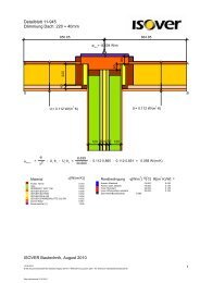
A dry system, easy to install<br />
The <strong>OPTIMA</strong> <strong>System</strong> is quick and easy to install, clean and dry. In contrast to traditional dry lining<br />
solutions, adhesives and glues are not needed, allowing installation in unheated rooms or during<br />
periods of frost.<br />
1. Installation of <strong>OPTIMA</strong> Floor and Ceiling Studs<br />
The position of the <strong>OPTIMA</strong> Floor and Ceiling Studs is determined by the width of the window frame<br />
(Picture 1, point T) minus the thickness of the facing. Check the frames reference points to ensure<br />
correct positioning of the <strong>OPTIMA</strong> Floor and Ceiling Studs and correct any possible misalignment.<br />
Mechanical Installation according to the support:<br />
• Pistocelling (ideal for concrete slabs)<br />
• Plugs to be hammered (screw + plug)<br />
If the ceiling is made of concrete blocks, the upper corners can be attached with expansion plugs. To<br />
ensure the joint between the <strong>OPTIMA</strong> Floor and Ceiling Studs, and the support is air tight VARIO DB<br />
band should be used (Picture 2). Installation in humid rooms requires the necessary protection for<br />
such joints.<br />
(A) <strong>OPTIMA</strong> Floor and Ceiling Studs<br />
(B) VARIO DB<br />
(C) <strong>OPTIMA</strong> 240 Stud (horizontal)<br />
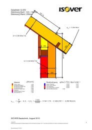
2. Installation of <strong>OPTIMA</strong> 240 Studs and <strong>OPTIMA</strong>2 Support<br />
In new buildings, horizontal <strong>OPTIMA</strong> 240 Studs are installed a maximum of 1.35 m from the floor<br />
(Picture 3). Depending on the facing and on wall geometry intermediate <strong>OPTIMA</strong>2 Supports are clipped<br />
every 60 cm (Picture 4). For renovation work <strong>OPTIMA</strong>2 Supports Reno are fixed directly to the wall.<br />
B<br />
T<br />
A<br />
A<br />
C<br />
1.35 m max<br />
1<br />
2<br />
3<br />
4<br />
15