download benjamin latham instruction manual
download benjamin latham instruction manual
download benjamin latham instruction manual

Create successful ePaper yourself
Turn your PDF publications into a flip-book with our unique Google optimized e-Paper software.
6. Main Pinrails<br />
These are simple swellings of the main rail on its inboard sides<br />
abreast of the main mast which hold the belaying (see lower<br />
right of figure 25). Note dimensions and their location on the<br />
hull plan. No alterations to the main rail are necessary for fitting<br />
the belaying pins at the fore shrouds.<br />
7. Boom Jiber Box<br />
This is an extension of the taffrail (main rail at the stern) and<br />
should be blended smoothly with it. Install the support chocks<br />
and prime and paint the area within them (check the color<br />
scheme in the section on Painting and Staining the Model).<br />
Then install the boom buffer hardware (also primed and painted).<br />
With this finished to your satisfaction, glue down the jiber<br />
box top, making sure that the block ring for the main sheet<br />
aligns properly with the opening. Since this detail is now essentially<br />
complete, be sure that you are satisfied with your<br />
workmanship, because these parts will be quite inaccessible<br />
later, if repairs are needed or afterthoughts begin to haunt you.<br />
8. Scuppers<br />
As can be seen on the bulwarks and rigging profiles of the<br />
plans, the bulwarks of the Benjamin W. Latham are pierced with<br />
many scupper holes. These openings on the real ship permitted<br />
rapid drainage of water which frequently found its way over<br />
the lee rail in heavy weather. They measured 1” x 5” but on the<br />
model are mere slits measuring 1/50” high x 1/10” long. One<br />
of the greatest pitfalls encountered in the modeling process is<br />
creating these holes grossly over scale. If you feel confident<br />
that you can drill or punch them out and retain a true-scale effect,<br />
go ahead and try it. Otherwise, a convincing effect can be<br />
produced by making slight indentations in the bulwarks on the<br />
outboard side, using an old small screwdriver that has be<br />
ground down to 1/10” in width and sharpened to a chisel<br />
edge. Scribe lines outboard at main and quarter deck levels and<br />
locate the scuppers so they lay on either or both sides of the<br />
timberheads as shown on the plans. Remember, the holes were<br />
meant to let water out, not three pound mackerels! As noted<br />
earlier in the <strong>instruction</strong>s, you may cut the scuppers before installing<br />
the bulwark planking.<br />
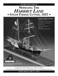
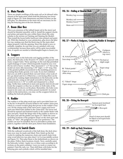
9. Rudder<br />
The rudder is of the plug-stock type and is provided laser-cut<br />
in the kit. It should be securely bolted to the rudder/stern post,<br />
which is a round wooden plug that pivots on the rudder’s true<br />
axis. Fit the stump-ends of the stern post’s upper and lower<br />
parts into blind holes drilled in the center keel. The lower end<br />
should be tapered and fastened neatly to the rudder blade with<br />
glue and pins. Notch the hinge-side of the rudder as shown on<br />
the plans and add the pintles (see figure 27). Mark the corresponding<br />
locations of the gudgeon straps on the stern post and<br />
make, or “fake”, the gudgeons to suit your preference. The<br />
rudder can now be installed, but it is advisable to prime and<br />
paint it, together with the stern post, before final installation.<br />
FIG. 26 – Railing at Quarter Deck<br />
Monkey log<br />
Monkey rail<br />
Monkey board<br />
Main rail<br />
FIG. 27 – Pintles & Gudgeons, Connecting Rudder & Sternpost<br />
A. Actual practice<br />
Iron strap<br />
B. “Faked pintle”<br />
Paper or<br />
shim strap<br />
C. “Faked” hinge<br />
Paper straps<br />
Pin forged<br />
to strap<br />
Gudgeon<br />
“padded out”<br />
FIG. 28 – Fitting the Bowsprit<br />
Gudgeon<br />
(above is<br />
top view)<br />
Pin bent at<br />
slight angle<br />
Paper strap<br />
Samson post mortised<br />
for bowsprit heel<br />
Bowsprit<br />
Eyebolt<br />
Drift pin<br />
Head of stem post should<br />
be fitted so bowsprit beds<br />
snugly on it<br />
10. Cleats & Snatch Cleats<br />
With the outboard woodwork of the hull done, the deck structures<br />
now may be made and fitted. First, finish up the bulwarks<br />
by making the numerous cleats and snatch cleats from<br />
strip-wood leftovers (see plan sheet 3 of 4 at top middle section<br />
and figure 31). Then glue them to the timberheads as shown on<br />
the plans. Follow these locations closely. Next, carefully paint<br />
the bulwarks (white). Apply two or three coats according to directions<br />
on the paint container. Leave no nook or cranny unpainted.<br />
Paint the rails, too. Then drill them with holes for the<br />
belaying pins and eyebolts which will be installed later.<br />
FIG. 29 – Built-up Deck Structures<br />
Forward companionway<br />
(forward side)<br />
Chain box<br />
21